|
|
|
Porsche, and the Porsche crest are registered trademarks of Dr. Ing. h.c. F. Porsche AG.
This site is not affiliated with Porsche in any way. Its only purpose is to provide an online forum for car enthusiasts. All other trademarks are property of their respective owners. |
|
|

  |

| bbrock |
 Jan 22 2021, 08:42 AM Jan 22 2021, 08:42 AM
Post
#21
|
|
914 Guru  Group: Members Posts: 5,269 Joined: 17-February 17 From: Montana Member No.: 20,845 Region Association: Rocky Mountains |
QUOTE(Superhawk996 @ Jan 22 2021, 05:56 AM)  QUOTE(bbrock @ Jan 21 2021, 09:31 PM) As for repairing a blown resistor - how important do you suppose it is to use an open coil resistor. Would something like this work as a replacement? https://www.digikey.com/en/products/detail/...A502R5J/2366322 It would definately work in the sense of functionality. I think the reason for the open coil resistors is available package space and better cooling. Looking at the size of the linked resistor, 2"L x 1"W and about the same 1" tall, I don't think it would fit. Could it have leads soldered to the resistor and then soldered to the OEM resistor holder and then mount the thing somewhere? Probably. I would be concerned about potential for the resistor to get hot enough to melt or deform plastic at 50W if JB welded to the housing or something like that. Drill holes for wires to exit the fan housing and mount that style resistor to the body as heat sink? (IMG:style_emoticons/default/screwy.gif) Sure, depends on how bad you really need a low or medium speed. (IMG:style_emoticons/default/laugh.gif) The key thing I don't know is how much current is the fan pulling at start up (peak in-rush) and what is is steady state operating current. Once we know that, we could properly size the resistors. 50W might be overkill? (IMG:style_emoticons/default/confused24.gif) Yeah, I was wondering more about the general package style than that particular resistor. The one I linked was just a random selection of twenty-seven 2.5 Ohm chassis mounted resistors that popped up on Digikey that had a nice picture since I didn't know particular power and dimension specs needed offhand. There are many options. For example, here's a 5w resistor only 0.6" long. https://www.digikey.com/en/products/detail/...5WM2D5/11650430 I was surprised not to find a selection of open coil style resistors on Digikey which makes me think either I don't know the correct search term to use, or perhaps that style has been superseded to a modern design for the application. With thousands of resistor options available for almost any given resistance rating, there are surely suitable off the shelf options out there. I picked the chassis mount to look at because they are mounted in heat sinks for heat dissipation which seems inline with the original design. You could mount those to a small aluminum plate with heat transfer paste for even more efficient heat dissipation. |
   |

 
|
| Mikey914 |
Jan 22 2021, 08:49 AM
Post
#22
|
|
The rubber man Group: Members Posts: 12,782 Joined: 27-December 04 From: Hillsboro, OR Member No.: 3,348 Region Association: None |
I'd look at a standard more "modern" resistor as a replacement. Pretty sure the only reason these are made like this is it was less expensive to build their own than buy them in 1969.
|
|
|
|
| DRPHIL914 |
Jan 22 2021, 08:51 AM
Post
#23
|
|
Dr. Phil Group: Members Posts: 5,947 Joined: 9-December 09 From: Kennesaw, GA Member No.: 11,106 Region Association: South East States |
QUOTE(bbrock @ Jan 22 2021, 09:42 AM) QUOTE(Superhawk996 @ Jan 22 2021, 05:56 AM) QUOTE(bbrock @ Jan 21 2021, 09:31 PM) As for repairing a blown resistor - how important do you suppose it is to use an open coil resistor. Would something like this work as a replacement? https://www.digikey.com/en/products/detail/...A502R5J/2366322 It would definately work in the sense of functionality. I think the reason for the open coil resistors is available package space and better cooling. Looking at the size of the linked resistor, 2"L x 1"W and about the same 1" tall, I don't think it would fit. Could it have leads soldered to the resistor and then soldered to the OEM resistor holder and then mount the thing somewhere? Probably. I would be concerned about potential for the resistor to get hot enough to melt or deform plastic at 50W if JB welded to the housing or something like that. Drill holes for wires to exit the fan housing and mount that style resistor to the body as heat sink? (IMG:style_emoticons/default/screwy.gif) Sure, depends on how bad you really need a low or medium speed. (IMG:style_emoticons/default/laugh.gif) The key thing I don't know is how much current is the fan pulling at start up (peak in-rush) and what is is steady state operating current. Once we know that, we could properly size the resistors. 50W might be overkill? (IMG:style_emoticons/default/confused24.gif) Yeah, I was wondering more about the general package style than that particular resistor. The one I linked was just a random selection of twenty-seven 2.5 Ohm chassis mounted resistors that popped up on Digikey that had a nice picture since I didn't know particular power and dimension specs needed offhand. There are many options. For example, here's a 5w resistor only 0.6" long. https://www.digikey.com/en/products/detail/...5WM2D5/11650430 I was surprised not to find a selection of open coil style resistors on Digikey which makes me think either I don't know the correct search term to use, or perhaps that style has been superseded to a modern design for the application. With thousands of resistor options available for almost any given resistance rating, there are surely suitable off the shelf options out there. I picked the chassis mount to look at because they are mounted in heat sinks for heat dissipation which seems inline with the original design. You could mount those to a small aluminum plate with heat transfer paste for even more efficient heat dissipation. |
 |
|
| Superhawk996 |
Jan 22 2021, 09:16 AM
Post
#24
|
|
914 Guru Group: Members Posts: 7,888 Joined: 25-August 18 From: Woods of N. Idaho Member No.: 22,428 Region Association: Galt's Gulch |
Not trying to be a kill joy on the DigiKey resistors but I suspect that in the desire to find a nice "modern" looking resistor you've over looking the physics and the cooling requirements.
These packaged high watt resistors require a heat sink to last. Once that aluminum case gets hot and has no heat sink to pull the heat away, it will get too hot and burn open in short order. That's why I referenced the idea of wires exiting the HVAC case and having to mount it on the sheetmetal body as a heat sink. Likewise, that style of heavy resistor if left unsupported within the blower case is going to fatigue the OEM resistor standoffs that were not designed to support that kind of resistor weight when dynamic road loads are imposed on it. A thick gauge wire wound resistor in open air is going to be able to handle more current and heat rejection than a nice neat ceramic or aluminum heat sink package that looks aerospace cool. I look at it as the industry having converged upon the best, most cost effective solution and it's not one of those DigiKey style resistors. Poke around on internet and you'll quickly find the converged solutions are resident in the blower case, they are air cooled. Typically open wire coil, large ceramic, or Solid State with big honking cooling fins in the air stream. You'll notice in a couple that the bi-metallic thermal cut out switch has been replaced by a more modern component though! 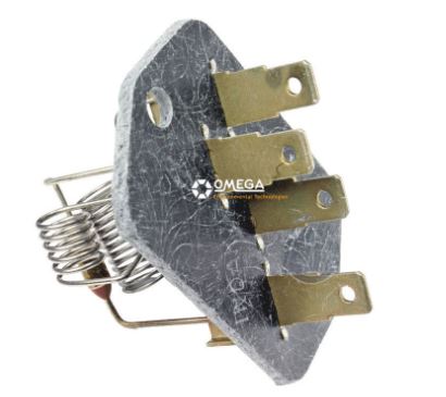 https://www.finditparts.com/products/594700...ASABEgJSDfD_BwE https://shop.advanceautoparts.com/p/bwd-hva...mp;gclsrc=aw.ds https://www.walmart.com/ip/Blower-Motor-Res...BCABEgI7CfD_BwE |
|
|
|
| bbrock |
Jan 22 2021, 09:03 PM
Post
#25
|
|
914 Guru Group: Members Posts: 5,269 Joined: 17-February 17 From: Montana Member No.: 20,845 Region Association: Rocky Mountains |
QUOTE(Superhawk996 @ Jan 22 2021, 08:16 AM) Not trying to be a kill joy on the DigiKey resistors but I suspect that in the desire to find a nice "modern" looking resistor you've over looking the physics and the cooling requirements. Wasn't trying to find a modern looking resistor. I was just trying to find any suitable replacement. I was actually searching for open coil resistors like what are in the blower and shocked not to be able to find them among the 500,000+ resistors in their catalog (or anywhere). I'm not saying they are not there, only that I couldn't find them. I am a bit offended though. (IMG:style_emoticons/default/happy11.gif) Even I'm not dumb enough to try to hang one of those chassis mount resistors from the OEM standoffs. I envisioned mounting to an aluminum plate, glued to the base of the resistor pack, and connected with flexible leads. Irrelevant if they are not suitable. I'm still puzzled why open wire coil resistors are not easier to find. Even resistor wire is kind of hard to find. All the stuff I've seen is annealed and too soft to make those spring like coils. |
|
|
|
| bdstone914 |
Jan 23 2021, 12:18 AM
Post
#26
|
|
bdstone914 Group: Members Posts: 5,322 Joined: 8-November 03 From: Riverside CA Member No.: 1,319 |
QUOTE(bbrock @ Jan 22 2021, 09:03 PM) QUOTE(Superhawk996 @ Jan 22 2021, 08:16 AM) Not trying to be a kill joy on the DigiKey resistors but I suspect that in the desire to find a nice "modern" looking resistor you've over looking the physics and the cooling requirements. Wasn't trying to find a modern looking resistor. I was just trying to find any suitable replacement. I was actually searching for open coil resistors like what are in the blower and shocked not to be able to find them among the 500,000+ resistors in their catalog (or anywhere). I'm not saying they are not there, only that I couldn't find them. I am a bit offended though. Even I'm not dumb enough to try to hang one of those chassis mount resistors from the OEM standoffs. I envisioned mounting to an aluminum plate, glued to the base of the resistor pack, and connected with flexible leads. Irrelevant if they are not suitable. I'm still puzzled why open wire coil resistors are not easier to find. Even resistor wire is kind of hard to find. All the stuff I've seen is annealed and too soft to make those spring like coils. @bbrock I can supply you a good used resistor assembly. |
|
|
|
| bbrock |
Jan 23 2021, 02:04 AM
Post
#27
|
|
914 Guru Group: Members Posts: 5,269 Joined: 17-February 17 From: Montana Member No.: 20,845 Region Association: Rocky Mountains |
QUOTE(bdstone914 @ Jan 22 2021, 11:18 PM) QUOTE(bbrock @ Jan 22 2021, 09:03 PM) QUOTE(Superhawk996 @ Jan 22 2021, 08:16 AM) Not trying to be a kill joy on the DigiKey resistors but I suspect that in the desire to find a nice "modern" looking resistor you've over looking the physics and the cooling requirements. Wasn't trying to find a modern looking resistor. I was just trying to find any suitable replacement. I was actually searching for open coil resistors like what are in the blower and shocked not to be able to find them among the 500,000+ resistors in their catalog (or anywhere). I'm not saying they are not there, only that I couldn't find them. I am a bit offended though. Even I'm not dumb enough to try to hang one of those chassis mount resistors from the OEM standoffs. I envisioned mounting to an aluminum plate, glued to the base of the resistor pack, and connected with flexible leads. Irrelevant if they are not suitable. I'm still puzzled why open wire coil resistors are not easier to find. Even resistor wire is kind of hard to find. All the stuff I've seen is annealed and too soft to make those spring like coils. @bbrock I can supply you a good used resistor assembly. Thanks Bruce, Mine's actually in excellent condition and working well. I was just curious what replacement options for resistors were. It shouldn't be as hard as it seems to be. I get a perverse pleasure out of such challenges. |
|
|
|
| Superhawk996 |
Jan 24 2021, 12:18 PM
Post
#28
|
|
914 Guru Group: Members Posts: 7,888 Joined: 25-August 18 From: Woods of N. Idaho Member No.: 22,428 Region Association: Galt's Gulch |
QUOTE(bbrock @ Jan 22 2021, 10:03 PM) @bbrock Here to serve! (IMG:style_emoticons/default/lol-2.gif) I'm sure with a little time, you'd master the process to harden and then temper the annealed wire properly to roll your own! |
|
|
|
| Superhawk996 |
Jan 24 2021, 12:35 PM
Post
#29
|
|
914 Guru Group: Members Posts: 7,888 Joined: 25-August 18 From: Woods of N. Idaho Member No.: 22,428 Region Association: Galt's Gulch |
Well it turns out I will be posting a WTB.
My blower works on all three speeds but the plastic housing is pretty rough. Cracked, missing clips that hold the 1/2's together, and one set of clip mounts is broken off completely. Motor vibrates like bearings/bushings are worn and/or needs to be rebalanced. Not sure who messed with my car somewhere in it's life but it was certainly owned at some point by the type of person that you could lock in an empty room, alone with two ball bearings. Come back 1 hour later and they would have broken one and lost the other. (IMG:style_emoticons/default/av-943.gif) OK, here are my measurements. Hope this helps you troubleshoot yours. @DRPHIL914  All were measured at 70F so amperage could be sustantially higher on cold morning with a sluggish motor that is drawing current closer to stall current. I'm surprised at the current this little bugger of a motor can draw! No wonder it's on a 25A fuse! 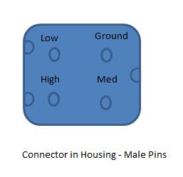 |
|
|
|
| DRPHIL914 |
Jan 24 2021, 07:03 PM
Post
#30
|
|
Dr. Phil Group: Members Posts: 5,947 Joined: 9-December 09 From: Kennesaw, GA Member No.: 11,106 Region Association: South East States |
QUOTE(Superhawk996 @ Jan 24 2021, 01:35 PM) Well it turns out I will be posting a WTB. My blower works on all three speeds but the plastic housing is pretty rough. Cracked, missing clips that hold the 1/2's together, and one set of clip mounts is broken off completely. Motor vibrates like bearings/bushings are worn and/or needs to be rebalanced. Not sure who messed with my car somewhere in it's life but it was certainly owned at some point by the type of person that you could lock in an empty room, alone with two ball bearings. Come back 1 hour later and they would have broken one and lost the other. (IMG:style_emoticons/default/av-943.gif) OK, here are my measurements. Hope this helps you troubleshoot yours. @DRPHIL914 All were measured at 70F so amperage could be sustantially higher on cold morning with a sluggish motor that is drawing current closer to stall current. I'm surprised at the current this little bugger of a motor can draw! No wonder it's on a 25A fuse! thanks foe the info, just pulled my original fan and housing and just sitting here checking resistance of each circuit i get less than 1 ohm on each one , in fact all 3 test at about .8. so i guess new resistor pack is necessary, but i will be pulling this apart, the fan does not turn easily, new bearing ans seals and maybe motor , will see if i can clean it all up once it’s out , doesn’t look too good, it’s been apart before someone put it back together and used silicone sealant between the upper and lower parts ugh. Attached thumbnail(s) 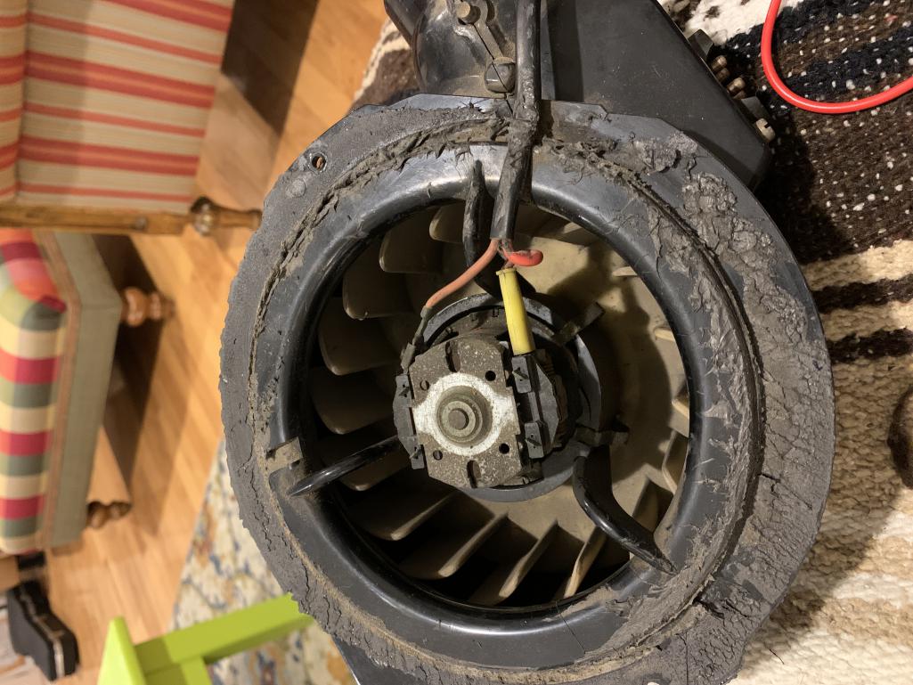
|
|
|
|
| Superhawk996 |
Jan 25 2021, 06:42 AM
Post
#31
|
|
914 Guru Group: Members Posts: 7,888 Joined: 25-August 18 From: Woods of N. Idaho Member No.: 22,428 Region Association: Galt's Gulch |
@DRPHIL914
" . . . so i guess new resistor pack is necessary". Not mentioning to beat you up but to reinforce how it important RULE #1 is in electrical trouble shooting. We've all done this. It was trained out of me and then has been proven by over 30 years of troubleshooting both electrical and mechanical systems. Sounds to me first thing to do is to pull the resistor pack. Verify -- don't assume. Resistors usually fail open. It is very rare for a resistor to fail as a short. If you have 0.8 ohms on all three, it sounds to me like the bimetallic switches are continiously closed. Could be similar to Brent's situation. In his case, he had one of them closed all the time and tweaked it with a pair of pliers to be normally open as it should be. Testing with DMM can verify this. 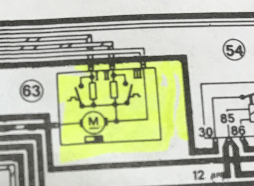 However, if this is the case, you really should have 3 high speeds already. You can bench test the fan with 12v battery and some wire jumpers. Did you try that by chance? Lack of airflow could have overheated the resistors and caused the bi-metallic switches to become deformed and to have become normally closed instead of normally open per the schematic. That is a theory and an assumption. A bench test of the reistor pack and of the fan itself will verify or disprove that hypothesis. |
|
|
|
| DRPHIL914 |
Jan 25 2021, 07:10 AM
Post
#32
|
|
Dr. Phil Group: Members Posts: 5,947 Joined: 9-December 09 From: Kennesaw, GA Member No.: 11,106 Region Association: South East States |
QUOTE(Superhawk996 @ Jan 25 2021, 07:42 AM) @DRPHIL914 " . . . so i guess new resistor pack is necessary". Not mentioning to beat you up but to reinforce how it important RULE #1 is in electrical trouble shooting. We've all done this. It was trained out of me and then has been proven by over 30 years of troubleshooting both electrical and mechanical systems. Sounds to me first thing to do is to pull the resistor pack. Verify -- don't assume. Resistors usually fail open. It is very rare for a resistor to fail as a short. If you have 0.8 ohms on all three, it sounds to me like the bimetallic switches are continiously closed. Could be similar to Brent's situation. In his case, he had one of them closed all the time and tweaked it with a pair of pliers to be normally open as it should be. Testing with DMM can verify this. However, if this is the case, you really should have 3 high speeds already. You can bench test the fan with 12v battery and some wire jumpers. Did you try that by chance? Lack of airflow could have overheated the resistors and caused the bi-metallic switches to become deformed and to have become normally closed. That is a theory and an assumption. A bench test will verify that hypothesis. completely agree, but just didnt have time last night, plan for tonight is to bench test wit the batter charger, put 12 volts in there and see what we get, then pull it out so i can inspect the resistor pack up close, see if that bi-metallic strip is stuck together. so will verify . the resistance values seemed strange to me to, was trying to figure out how it would fail that way. fan does not spin freely so so doubt i have to get this one pulled apart and cleaned up and see if lub will help. Ive heard that the motors really dont fail or burn out often, dont know if that is true, But talked to Bruce Stone over the weekend and he suggested doing the same bench test, inspection, etc. and i have all new seals and hardware coming from Mark too. will report back tonight. |
|
|
|
| Superhawk996 |
Jan 25 2021, 07:24 AM
Post
#33
|
|
914 Guru Group: Members Posts: 7,888 Joined: 25-August 18 From: Woods of N. Idaho Member No.: 22,428 Region Association: Galt's Gulch |
QUOTE(DRPHIL914 @ Jan 25 2021, 08:10 AM) . . . plan for tonight is to bench test wit the battery charger . . . Would be better to use a 12v battery as the source if you can. Battery chargers vary widely and some are really only 1/2 wave rectified and don't have a full 12 volt steady output. It can cause the fan motor to run slower than it would with a battery. Likewise, it may be current limited. I tested stall current with a battery and it pulled 15A or so. If the battery charger can only deliver 10A, you may not get full speed and/or have sufficient amperage to turn motor if it is binding a little. Here is what I mean by 1/2 wave output. Can go to site if you want more info.  |
|
|
|
| Superhawk996 |
Jan 25 2021, 07:38 AM
Post
#34
|
|
914 Guru Group: Members Posts: 7,888 Joined: 25-August 18 From: Woods of N. Idaho Member No.: 22,428 Region Association: Galt's Gulch |
@DRPHIL914
I'm going to pick one more snippet from your quote. Not trying to beat up on you personally, but, it speaks to Rule #2. If I'm making you mad by picking out snippets, I'll stop, just let me know. However, it illustrates how I got to the rules we started with. " . . . the resistance values seemed strange to me to, was trying to figure out how it would fail that way." This is why a good schematic is a must have. Depending on the complexity of the system, It can be hard, if not impossible troubleshoot effectively without a schematic. Good schematic from Haynes. B&W is a bit more work to read for color codes but all info is available. The schematic explains the switches, their normal position, and their operation.  Nice for color codes, but, a block diagram is useless for this type of troubleshooting. Explains nothing other than the colors of the wire. 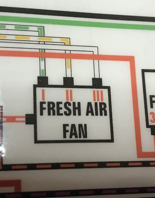 |
|
|
|
| DRPHIL914 |
Jan 25 2021, 08:09 AM
Post
#35
|
|
Dr. Phil Group: Members Posts: 5,947 Joined: 9-December 09 From: Kennesaw, GA Member No.: 11,106 Region Association: South East States |
QUOTE(Superhawk996 @ Jan 25 2021, 08:38 AM) @DRPHIL914 I'm going to pick one more snippet from your quote. Not trying to beat up on you personally, but, it speaks to Rule #2. If I'm making you mad by picking out snippets, I'll stop, just let me know. However, it illustrates how I got to the rules we started with. " . . . the resistance values seemed strange to me to, was trying to figure out how it would fail that way." This is why a good schematic is a must have. Depending on the complexity of the system, It can be hard, if not impossible troubleshoot effectively without a schematic. Good schematic from Haynes. B&W is a bit more work to read for color codes but all info is available. The schematic explains the switches, their normal position, and their operation. Nice for color codes, but, a block diagram is useless for this type of troubleshooting. Explains nothing other than the colors of the wire. no, please i appreciate the info, and being educated! help me understand the basics like being able to read the schematics will help me trouble shoot other issues in the future, so the M is the motor correct, and #3 high does not go thru either of the resistors, just the bimetalic plate? if the plate were not conducting current you would not get the fan to run on that setting and resistance with be infinity(short?) |
|
|
|
| Superhawk996 |
Jan 25 2021, 08:25 AM
Post
#36
|
|
914 Guru Group: Members Posts: 7,888 Joined: 25-August 18 From: Woods of N. Idaho Member No.: 22,428 Region Association: Galt's Gulch |
@DRPHIL914
so the M is the motor correct -- Yes, Correct and #3 high does not go thru either of the resistors -- Correct . . if the plate were not conducting current you would not get the fan to run on that setting -- can't really answer that question without a physical inspection of the assembly. I tried to look at BeatNavy's photos and I still can't tell for sure. However, I can see from the photo the plate is basically a thick, solid copper trace. The chance of that opening up is slim to none. The amount of current it would take to melt that open would have melted the external wiring 1st. I think I might be misunderstanding the question. Let's call the switches; bi-metallics switches. What I'm calling the plate is the structure that the reistors and the bi-metallic switches are attached to. So when a bi-metallic switch is normally open you would read the resistance of the Motor + the resistor. When the bi-metallic switch is closed (should only be when the resistor is over heating), the bi-metallic switch deforms to the closed position, and bypasses the resistor with a short (zero ohm) connection, and the motor would run in high speed (just like position #3), the fan should pull more air across the resistor, cool it down, and then the bi-metallic switch should return to the normally open position and the fan would return to its regulated speed. If the bi-metallic switch were permanently deformed to be normaly closed (even when cool) then you would read the motor resistance only just like you would in position #3. and resistance with be infinity(short?) -- A short = 0 ohms, open circuit = infinity. Since you are reading 0.8 ohm on all three speeds, we know the plate is not open and, that we have conductivity between all three potential current paths though the motor Adding on: Around each resistor, you see a switch that operates as a square wave. Either OFF or ON. When that switch closes, you have a short around the wire wound resistor. Therefore, you would only read the motor winding resistance when measuring though the switch if this switch were closed. These are the bi-metallic switches that are located blow the resitors in Brent's photo. Note: DMM's can have 0.1- 0.3 ohm of resistance just in the leads (especially if using add-on's like alligator clips. My cheap DMM reads 0.2 ohms with a dead short and alligator clips attached. So moral of the story is your ohm readings may differ slightly and/or a dead short may still show as 0.2 ohms or so. |
|
|
|
| DRPHIL914 |
Jan 25 2021, 06:14 PM
Post
#37
|
|
Dr. Phil Group: Members Posts: 5,947 Joined: 9-December 09 From: Kennesaw, GA Member No.: 11,106 Region Association: South East States |
took the sucker apart and retested the resistor pack without being hooked up to motor,
values are: Low- 1.5 Medium- 3.4 high- 1-1.5 @Superhawk996 pictures of it show both bimetallic strips in good condition and open Attached thumbnail(s) 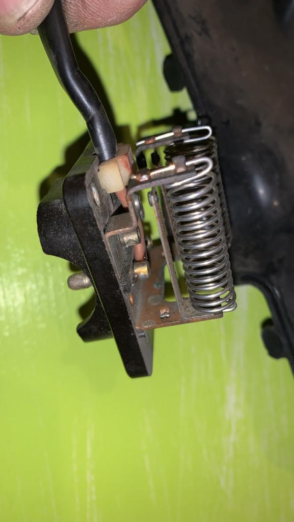 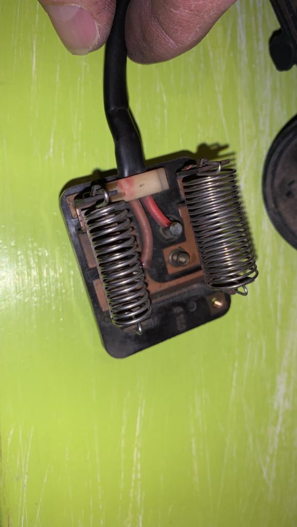
|
|
|
|
| bbrock |
Jan 25 2021, 07:19 PM
Post
#38
|
|
914 Guru Group: Members Posts: 5,269 Joined: 17-February 17 From: Montana Member No.: 20,845 Region Association: Rocky Mountains |
QUOTE(DRPHIL914 @ Jan 25 2021, 05:14 PM) took the sucker apart and retested the resistor pack without being hooked up to motor, values are: Low- 1.5 Medium- 3.4 high- 1-1.5 @Superhawk996 pictures of it show both bimetallic strips in good condition and open Where are placing the probes to measure resistance and do you see any resistance specs on the resistor pack? My is stamped 2.5 ohms for the low speed resistor and 0.75 for medium speed. Measuring resistance with probes on each end of the resistor, I got 2.5 ohms on the nose for the low side, and 1.1 ohms on the medium side. The medium sides was higher than what was stamped but works okay so I think those stamps are ballpark. |
|
|
|
| Superhawk996 |
Jan 26 2021, 06:11 AM
Post
#39
|
|
914 Guru Group: Members Posts: 7,888 Joined: 25-August 18 From: Woods of N. Idaho Member No.: 22,428 Region Association: Galt's Gulch |
@DRPHIL914
Agree with @bbrock 's comments, need to know exactly where you measured from both initially and on this latest round of measurements. Before we go there, let's acknowlege something changed that doesn't make sense. If you were measuring 0.8 ohms on all three settings before and now you're measuring higher resistances with the resistor pack disconnected from the motor, something is wrong. The motor + a resistance value should always be higher than just measuring the resistors alone. Since resistances went up since 1st round, something isn't correct. Another key item that is basic to electronics work is that in order to measure resistance, the component (or system) under measurement must be disconnected from the rest of the system. For example, we cannot measure the resistance of the fresh air motor + resistor with the motor assembly plugged into the rest of the vehicle wiring and HVAC slider controls. I assumed the fresh air box was completely disconnected from the vehicle when the 0.8 ohms was reported but maybe I made a bad assumption despite my own Rule #1. (IMG:style_emoticons/default/laugh.gif) See, we all do it despite our best attempt. This is probably a good point to talk about Rule #4, half splitting. The goal is to divide things in 1/2 to isolate which side the problem is on. By disconnecting the fan motor & resistor assembly, we dive the system into two. The vehicle side (vehicle wiring, HVAC control, connectors) and the fresh air box assembly (motor, resistor, and the short bit of wire inside). I had assumed we were working on just the 1/2 system of the fresh air box completely disconnected from the vehicle and wiring. Is that valid? To continue the 1/2 split conversation, we can now split the fresh air box system in 1/2 again. We can divide system to the motor only disconnected from the resistor pack, and the resistor+stub of wire that connects to the motor. So on the resitor pack; disconnected from the motor, (1/4 of the sytem as we currently have it divided) I'd like you to measure the resistors only (measure one resistor post to the other resistor post) with nothing else connected to it. That will give us the value of the two resistors alone. By inspection we can see the bi-metallic switches are open. We might measure that later just to be sure but for now let's just get the resistor values and see if they come close to Brent's or BeatNavy's measurements and/or markings on the housing. The other thing we can do is to measure the other 1/4 of the system (the motor only). With the resistor pack disconnected from the motor, what does the motor resistance measure? Does it change drasticallywhen you rotate the position of the fan impeller from one position to another? We can also physically test just the fan -- it can be hooked to a 12 volt battery to see if it spins. Let's try this and see where we end up as we try to resolve why the system changed. Worst case, we will put the motor + resistor 1/2 of the system back together and can see if we can duplicate your original 0.8 ohm measurements. Not likely to have to do this once we go through the steps above. |
|
|
|
| DRPHIL914 |
Jan 26 2021, 10:27 AM
Post
#40
|
|
Dr. Phil Group: Members Posts: 5,947 Joined: 9-December 09 From: Kennesaw, GA Member No.: 11,106 Region Association: South East States |
QUOTE(Superhawk996 @ Jan 26 2021, 07:11 AM) @DRPHIL914 Agree with @bbrock 's comments, need to know exactly where you measured from both initially and on this latest round of measurements. Before we go there, let's acknowlege something changed that doesn't make sense. If you were measuring 0.8 ohms on all three settings before and now you're measuring higher resistances with the resistor pack disconnected from the motor, something is wrong. The motor + a resistance value should always be higher than just measuring the resistors alone. Since resistances went up since 1st round, something isn't correct. Another key item that is basic to electronics work is that in order to measure resistance, the component (or system) under measurement must be disconnected from the rest of the system. For example, we cannot measure the resistance of the fresh air motor + resistor with the motor assembly plugged into the rest of the vehicle wiring and HVAC slider controls. I assumed the fresh air box was completely disconnected from the vehicle when the 0.8 ohms was reported but maybe I made a bad assumption despite my own Rule #1. (IMG:style_emoticons/default/laugh.gif) See, we all do it despite our best attempt. This is probably a good point to talk about Rule #4, half splitting. The goal is to divide things in 1/2 to isolate which side the problem is on. By disconnecting the fan motor & resistor assembly, we dive the system into two. The vehicle side (vehicle wiring, HVAC control, connectors) and the fresh air box assembly (motor, resistor, and the short bit of wire inside). I had assumed we were working on just the 1/2 system of the fresh air box completely disconnected from the vehicle and wiring. Is that valid? To continue the 1/2 split conversation, we can now split the fresh air box system in 1/2 again. We can divide system to the motor only disconnected from the resistor pack, and the resistor+stub of wire that connects to the motor. So on the resitor pack; disconnected from the motor, (1/4 of the sytem as we currently have it divided) I'd like you to measure the resistors only (measure one resistor post to the other resistor post) with nothing else connected to it. That will give us the value of the two resistors alone. By inspection we can see the bi-metallic switches are open. We might measure that later just to be sure but for now let's just get the resistor values and see if they come close to Brent's or BeatNavy's measurements and/or markings on the housing. The other thing we can do is to measure the other 1/4 of the system (the motor only). With the resistor pack disconnected from the motor, what does the motor resistance measure? Does it change drasticallywhen you rotate the position of the fan impeller from one position to another? We can also physically test just the fan -- it can be hooked to a 12 volt battery to see if it spins. Let's try this and see where we end up as we try to resolve why the system changed. Worst case, we will put the motor + resistor 1/2 of the system back together and can see if we can duplicate your original 0.8 ohm measurements. Not likely to have to do this once we go through the steps above. i can do more of this tonight. to answer a few questions, when i tested it and got the.8, we had the 1/2 split, i was testing the fan assembly out of the car, but motor in and i dont know what was wrong with reading but fan was hooked up , my new readings were with the fan split so just testing the resistors from neutral to each lead with aligator clips and did it with the probe on end or side of the male connector and reuslt was exactly the same, the 1.5, 3.5 and 1.0 for high which seems strange . i will try and test the fan motor tonight and give it power, see how it turns, Phil now we can test the sliders by its self, i tried but was not doing something correctly as i didnt get a proper value. |
|
|
|
|
2 User(s) are reading this topic (1 Guests and 0 Anonymous Users)
1 Members: tlehman914

|
Lo-Fi Version | Time is now: 15th June 2026 - 02:44 PM |
Invision Power Board
v9.1.4 © 2026 IPS, Inc.