|
|
|
Porsche, and the Porsche crest are registered trademarks of Dr. Ing. h.c. F. Porsche AG.
This site is not affiliated with Porsche in any way. Its only purpose is to provide an online forum for car enthusiasts. All other trademarks are property of their respective owners. |
|
|


| bkrantz |
 Jan 24 2021, 08:31 PM Jan 24 2021, 08:31 PM
Post
#21
|
|
914 Guru  Group: Members Posts: 8,493 Joined: 3-August 19 From: SW Colorado Member No.: 23,343 Region Association: Rocky Mountains |
What do you all think of this location for mounting my new pump in the front?
Besides space, I have some other goals: 1. Avoiding mounting on any sheet metal shared with the passenger compartment. 2. As much protection as possible. 3. Short fuel line runs between the tank, filter, pump, and hard lines. 4. Access to the lines without pulling the tank. 5. Access to the pump without pulling the tank. My proposed location probably does not satisfy goal 5 (maybe), but otherwise I like it. Attached thumbnail(s) 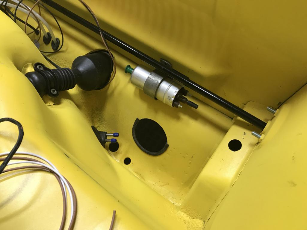
|
   |

 
|
Posts in this topic
 bkrantz Advice: Fuel Pump Relocation Location Jan 24 2021, 08:31 PM
 r_towle I think if you take a look at the later model cars... Jan 24 2021, 08:44 PM
 ndfrigi
I think if you take a look at the later model car... Jan 24 2021, 08:46 PM Highland
[quote name='r_towle' post='2885482' date='Jan 24... Jan 29 2021, 03:38 PM bkrantz I do know about the stock 75-76 location on the le... Jan 24 2021, 09:19 PM Montreal914
I do know about the stock 75-76 location on the l... Jan 24 2021, 09:32 PM rgalla9146
I do know about the stock 75-76 location on the l... Mar 12 2021, 09:05 AM r_towle Based upon my multiple locations, and my big hands... Jan 24 2021, 10:44 PM JamesM I always move them to either one of the 2 location... Jan 25 2021, 01:00 AM Jamie
I always move them to either one of the 2 locatio... Jan 25 2021, 10:52 AM mlindner Same goals, up front, good access to pump and filt... Jan 25 2021, 04:47 AM Olympic 914 I just went through this myself. Pump is also mou... Jan 25 2021, 08:41 AM Shivers Could one of you guy's post a few pics for us ... Jan 25 2021, 09:58 AM ndfrigi
Could one of you guy's post a few pics for us... Jan 25 2021, 10:06 AM Shivers
Could one of you guy's post a few pics for u... Jan 25 2021, 11:46 AM bbrock
Could one of you guy's post a few pics for us... Jan 25 2021, 02:10 PM Shivers
[quote name='Shivers' post='2885607' date='Jan 25... Jan 25 2021, 04:44 PM JeffBowlsby Don't forget the pair of ~1" thick rubber... Jan 25 2021, 11:26 AM Jamie
Don't forget the pair of ~1" thick rubbe... Jan 25 2021, 11:40 AM jim_hoyland Moved the pump from behind the firewall to the fro... Jan 25 2021, 12:06 PM jim_hoyland Moved the pump from behind the firewall to the fro... Jan 25 2021, 12:06 PM Jamie
Moved the pump from behind the firewall to the fr... Jan 25 2021, 07:55 PM jhynesrockmtn I went through this over the winter. My car is a ... Jan 25 2021, 02:29 PM Jamie
I went through this over the winter. My car is a... Jan 25 2021, 07:57 PM mlindner Jim hoyland, thats sharp, nice job. Mark Jan 25 2021, 03:32 PM 914werke Could one of you guy's post a few pics for 7... Jan 25 2021, 06:42 PM bkrantz Thanks, everyone. I have gone ahead with my idea ... Jan 25 2021, 08:09 PM bkrantz Here's the hole from above.
More pics when I ... Jan 25 2021, 08:11 PM 914_teener
What do you all think of this location for mounti... Jan 25 2021, 08:17 PM bkrantz
What do you all think of this location for mount... Jan 26 2021, 09:02 PM iankarr Looks like a great spot. Only thing I’m curious ... Jan 26 2021, 09:36 PM 914_teener
Looks like a great spot. Only thing I’m curious... Jan 28 2021, 03:19 PM bkrantz
Looks like a great spot. Only thing I’m curiou... Jan 28 2021, 10:48 PM ClayPerrine I have mounted 914 fuel pumps in the location show... Jan 28 2021, 03:28 PM 914_teener
I have mounted 914 fuel pumps in the location sho... Jan 28 2021, 03:44 PM robkammer Those are some great shots of pump relo's. I... Feb 21 2021, 04:26 PM robkammer Thanks everyone! Great feedback and good pics ... Mar 12 2021, 06:21 AM rhodyguy Any sort of service, like changing the filter, res... Mar 12 2021, 02:17 PM Van B Reviving this thread because it comes up in search... Feb 18 2023, 02:35 PM FJ1200 A little late to the party, but here you go
https... Aug 9 2023, 11:30 AM second wind I have to pitch in as I just did this to my '7... Aug 9 2023, 05:08 PM stoneman30hotmail This thread is what comes up for pump relocation b... Oct 6 2023, 07:17 PM ILM914 Hot my pump relocation kit from George at Auto Atl... Oct 6 2023, 07:43 PM Geezer914 I mounted mine on the steering rack. I took the f... Oct 7 2023, 06:30 AM
ndfrigi
I think if you take a look at the later model car... Jan 24 2021, 08:46 PM Highland
[quote name='r_towle' post='2885482' date='Jan 24... Jan 29 2021, 03:38 PM bkrantz I do know about the stock 75-76 location on the le... Jan 24 2021, 09:19 PM Montreal914
I do know about the stock 75-76 location on the l... Jan 24 2021, 09:32 PM rgalla9146
I do know about the stock 75-76 location on the l... Mar 12 2021, 09:05 AM r_towle Based upon my multiple locations, and my big hands... Jan 24 2021, 10:44 PM JamesM I always move them to either one of the 2 location... Jan 25 2021, 01:00 AM Jamie
I always move them to either one of the 2 locatio... Jan 25 2021, 10:52 AM mlindner Same goals, up front, good access to pump and filt... Jan 25 2021, 04:47 AM Olympic 914 I just went through this myself. Pump is also mou... Jan 25 2021, 08:41 AM Shivers Could one of you guy's post a few pics for us ... Jan 25 2021, 09:58 AM ndfrigi
Could one of you guy's post a few pics for us... Jan 25 2021, 10:06 AM Shivers
Could one of you guy's post a few pics for u... Jan 25 2021, 11:46 AM bbrock
Could one of you guy's post a few pics for us... Jan 25 2021, 02:10 PM Shivers
[quote name='Shivers' post='2885607' date='Jan 25... Jan 25 2021, 04:44 PM JeffBowlsby Don't forget the pair of ~1" thick rubber... Jan 25 2021, 11:26 AM Jamie
Don't forget the pair of ~1" thick rubbe... Jan 25 2021, 11:40 AM jim_hoyland Moved the pump from behind the firewall to the fro... Jan 25 2021, 12:06 PM jim_hoyland Moved the pump from behind the firewall to the fro... Jan 25 2021, 12:06 PM Jamie
Moved the pump from behind the firewall to the fr... Jan 25 2021, 07:55 PM jhynesrockmtn I went through this over the winter. My car is a ... Jan 25 2021, 02:29 PM Jamie
I went through this over the winter. My car is a... Jan 25 2021, 07:57 PM mlindner Jim hoyland, thats sharp, nice job. Mark Jan 25 2021, 03:32 PM 914werke Could one of you guy's post a few pics for 7... Jan 25 2021, 06:42 PM bkrantz Thanks, everyone. I have gone ahead with my idea ... Jan 25 2021, 08:09 PM bkrantz Here's the hole from above.
More pics when I ... Jan 25 2021, 08:11 PM 914_teener
What do you all think of this location for mounti... Jan 25 2021, 08:17 PM bkrantz
What do you all think of this location for mount... Jan 26 2021, 09:02 PM iankarr Looks like a great spot. Only thing I’m curious ... Jan 26 2021, 09:36 PM 914_teener
Looks like a great spot. Only thing I’m curious... Jan 28 2021, 03:19 PM bkrantz
Looks like a great spot. Only thing I’m curiou... Jan 28 2021, 10:48 PM ClayPerrine I have mounted 914 fuel pumps in the location show... Jan 28 2021, 03:28 PM 914_teener
I have mounted 914 fuel pumps in the location sho... Jan 28 2021, 03:44 PM robkammer Those are some great shots of pump relo's. I... Feb 21 2021, 04:26 PM robkammer Thanks everyone! Great feedback and good pics ... Mar 12 2021, 06:21 AM rhodyguy Any sort of service, like changing the filter, res... Mar 12 2021, 02:17 PM Van B Reviving this thread because it comes up in search... Feb 18 2023, 02:35 PM FJ1200 A little late to the party, but here you go
https... Aug 9 2023, 11:30 AM second wind I have to pitch in as I just did this to my '7... Aug 9 2023, 05:08 PM stoneman30hotmail This thread is what comes up for pump relocation b... Oct 6 2023, 07:17 PM ILM914 Hot my pump relocation kit from George at Auto Atl... Oct 6 2023, 07:43 PM Geezer914 I mounted mine on the steering rack. I took the f... Oct 7 2023, 06:30 AM  |
1 User(s) are reading this topic (1 Guests and 0 Anonymous Users)
0 Members:

|
Lo-Fi Version | Time is now: 7th September 2025 - 10:23 AM |
Invision Power Board
v9.1.4 © 2025 IPS, Inc.