|
|
|
Porsche, and the Porsche crest are registered trademarks of Dr. Ing. h.c. F. Porsche AG.
This site is not affiliated with Porsche in any way. Its only purpose is to provide an online forum for car enthusiasts. All other trademarks are property of their respective owners. |
|
|

  |

| DRPHIL914 |
 Sep 29 2021, 01:14 PM Sep 29 2021, 01:14 PM
Post
#21
|
|
Dr. Phil  Group: Members Posts: 5,767 Joined: 9-December 09 From: Bluffton, SC Member No.: 11,106 Region Association: South East States |
QUOTE(914_teener @ Sep 29 2021, 02:20 PM)  QUOTE(Spoke @ Sep 29 2021, 11:07 AM) @DRPHIL914 Phil, Please confirm these 2 tests: Remove the ECU 4-pin connector from the relay board. Remove the +12V wire from the coil to protect any components which might be affected by leaving the ignition ON with the engine not running. Turn ignition to ON 1) Measure voltage at ECU 4-pin connector terminal #1. What voltage to you have? 2) Ground ECU 4-pin connector terminal #3. Does the FP run continuously? Wow....look at that diagram. Nice. Do what Spoke says Phil. I had this problem long ago IIRC. Turned out to be a intermitent cut out and a sliced or cut in the wire out of that harness. Left me stranded at the Santa Monica Pier a while back.......probably 15 years ago now! QUOTE(Spoke @ Sep 29 2021, 02:31 PM) QUOTE(Spoke @ Sep 29 2021, 02:07 PM) 1) Measure voltage at ECU 4-pin connector terminal #1. What voltage to you have? 2) Ground ECU 4-pin connector terminal #3. Does the FP run continuously? @DRPHIL914 BTW, be very careful when measuring terminal 1. The power to terminal 1 comes through the power supply relay then straight to the battery WITHOUT a fuse. Likewise when grounding terminal 3 use a wire with a spade connector and not a bare wire to touch terminal 3. The ignition switch should be OFF when you attach the wire. Attach the wire then turn the ignition switch ON. Terminal 1 is not fused and catastrophic damage may occur if your ground wire on terminal 3 accidentally touches Terminal 1. good to know, will be very careful on this not to cause a short between the #3 ground and the #1 there when testing. I will get into this tonight and report back. - agreed, nice diagram, it makes it a bit easier to see the flow and understand. |
   |

 
|
| ClayPerrine |
Sep 30 2021, 11:22 AM
Post
#22
|
|
Life's been good to me so far..... Group: Admin Posts: 15,474 Joined: 11-September 03 From: Hurst, TX. Member No.: 1,143 Region Association: NineFourteenerVille |
We tried to call you from Okteenerfest, but didn't get through.
This may help... (IMG:http://www.914world.com/bbs2/uploads/post-1143-1610637417.jpg) On the ecu power supply relay, make sure pin 30 has constant power. (Red trace in diagram) With the key on, make sure there is power to pin 1 on the 4 pin connector for the injection harness. It could simply be the ecu power supply relay went bad. Clay |
 |
|
| adolimpio |
Sep 30 2021, 01:00 PM
Post
#23
|
|
Art Group: Members Posts: 181 Joined: 10-March 10 From: Greenwood SC Member No.: 11,449 Region Association: South East States |
I chatted with Phil this morning.
He has 12V at the coil which tells us that there is voltage on the circuit which supplies the ECU relay. That circuit comes into the relay board on pin 8 of the 14 pin connector, connects to pin 85 of the ECU and Heater fan relay and goes out on pin 7 of the 12 pin connector and on to the coil. He also said that he cannot hear or feel the relay click when plugging and unplugging it, and he said that it is an old conventional relay, not solid state. Given this, when he is off work later today, I asked him to: Check for 12V on pin 85 of ECU relay. If 12V is present on pin 85 then check for 12V between pins 85 and 86. If 12V is present between 85 & 86 then the relay should be replaced. If there is no voltage between 85 & 86, then it is a ground issue. If there is no 12V on pin 85, then a trace on the relay board must be defective and the relay board should be replaced. My money is on a ground issue! |
|
|
|
| adolimpio |
Sep 30 2021, 01:03 PM
Post
#24
|
|
Art Group: Members Posts: 181 Joined: 10-March 10 From: Greenwood SC Member No.: 11,449 Region Association: South East States |
QUOTE(Spoke @ Sep 29 2021, 02:07 PM) @DRPHIL914 Phil, Please confirm these 2 tests: Remove the ECU 4-pin connector from the relay board. Remove the +12V wire from the coil to protect any components which might be affected by leaving the ignition ON with the engine not running. Turn ignition to ON 1) Measure voltage at ECU 4-pin connector terminal #1. What voltage to you have? 2) Ground ECU 4-pin connector terminal #3. Does the FP run continuously? @spoke There is an error on your schematic. Pins 85 & 86 are swapped on the relays. |
|
|
|
| DRPHIL914 |
Sep 30 2021, 01:20 PM
Post
#25
|
|
Dr. Phil Group: Members Posts: 5,767 Joined: 9-December 09 From: Bluffton, SC Member No.: 11,106 Region Association: South East States |
QUOTE(ClayPerrine @ Sep 30 2021, 01:22 PM) We tried to call you from Okteenerfest, but didn't get through. This may help... (IMG:http://www.914world.com/bbs2/uploads/post-1143-1610637417.jpg) On the ecu power supply relay, make sure pin 30 has constant power. (Red trace in diagram) With the key on, make sure there is power to pin 1 on the 4 pin connector for the injection harness. It could simply be the ecu power supply relay went bad. Clay Clay, we were in a bad spot snd cell coverage was iffy zap i missed the call while we were trouble shooting, but on the spot thet day and again at home , also rechecked last night i had no power at the #1 spade, and i do have 12v at the board fuse and at the FP relay #30 but not at the power relay #30. i pulled th board last night ans cleaned the contact pins and also slid a razor into each pin to slightly push apart the pins to tighten up the contacts , rechecked all the body grounds ans the FI motor ground connection. tonight as Artmsaid i will go back and check the power relay #30, also the 85 ans 86 again. the relays were swapped and checked and i also have some new ones but anyway too good relays from the headlights and swapped snd it didn’t help. no change . either it’s a board short or grounding issue, hoping for the test tonight to help clarify it. Coil gets 12v and so does the starter. pretty sure it’s not the ignition because power is coming back from front to back thru the switch but ECU is not getting power or maybe not grounding . |
|
|
|
| Spoke |
Sep 30 2021, 05:56 PM
Post
#26
|
|
Jerry Group: Members Posts: 6,985 Joined: 29-October 04 From: Allentown, PA Member No.: 3,031 Region Association: None |
QUOTE(adolimpio @ Sep 30 2021, 03:03 PM) There is an error on your schematic. Pins 85 & 86 are swapped on the relays. @adolimpio Thanks for pointing that out. My Carbooks 914 1970-72 shop manual and Haynes 914 Owners Workshop Manual has 85 and 86 swapped. For Haynes, only the "up to 1971" picture is like my original. The 1972 and 1973 relay board pictures are correct. Here's my schematic corrected. 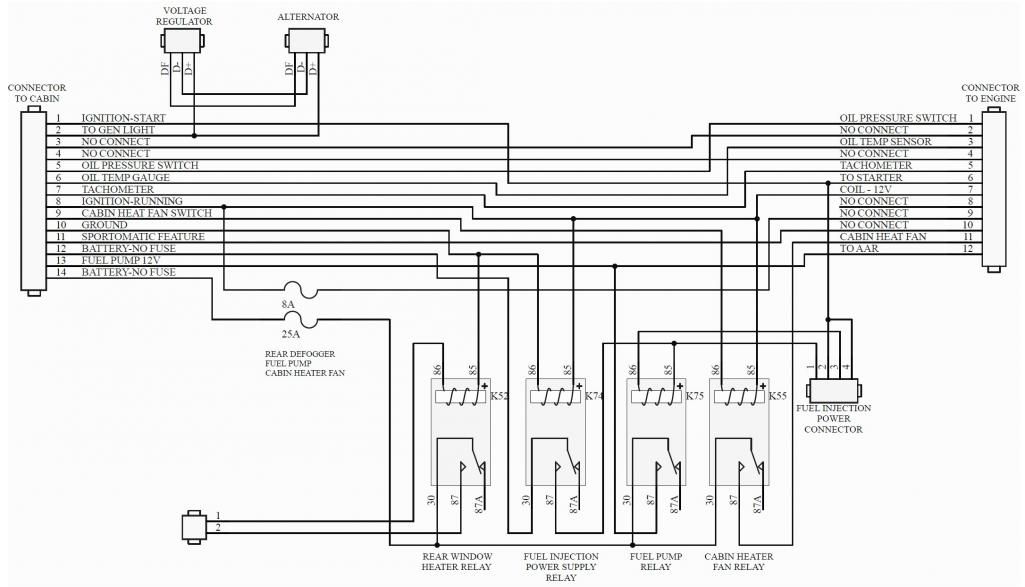 |
|
|
|
| Spoke |
Sep 30 2021, 06:11 PM
Post
#27
|
|
Jerry Group: Members Posts: 6,985 Joined: 29-October 04 From: Allentown, PA Member No.: 3,031 Region Association: None |
QUOTE(DRPHIL914 @ Sep 30 2021, 03:20 PM) have 12v at the board fuse and at the FP relay #30 but not at the power relay #30. @DRPHIL914 @adolimpio FP relay pin 30 comes through the 25A fuse from 14 pin connector pin 14 directly from the battery. Power Supply relay pin 30 power comes from 14 pin connector pin 12 directly from the battery. Pins 12 and 14 have separate wires directly to the battery. If the PS pin 30 has no power then either: 1) The socket and/or connection to the relay board for the Power Supply relay is suspect 2) The relay board traces to pin 12 is suspect 3) The pin 12 connector/pin is suspect 4) The wire from pin 12 to the battery is suspect |
|
|
|
| adolimpio |
Sep 30 2021, 07:02 PM
Post
#28
|
|
Art Group: Members Posts: 181 Joined: 10-March 10 From: Greenwood SC Member No.: 11,449 Region Association: South East States |
QUOTE(Spoke @ Sep 30 2021, 07:56 PM) QUOTE(adolimpio @ Sep 30 2021, 03:03 PM) There is an error on your schematic. Pins 85 & 86 are swapped on the relays. @adolimpio Thanks for pointing that out. My Carbooks 914 1970-72 shop manual and Haynes 914 Owners Workshop Manual has 85 and 86 swapped. For Haynes, only the "up to 1971" picture is like my original. The 1972 and 1973 relay board pictures are correct. Here's my schematic corrected. Nice, it's a nice piece of work. Thanks for fixing. |
|
|
|
| DRPHIL914 |
Sep 30 2021, 07:43 PM
Post
#29
|
|
Dr. Phil Group: Members Posts: 5,767 Joined: 9-December 09 From: Bluffton, SC Member No.: 11,106 Region Association: South East States |
QUOTE(Spoke @ Sep 30 2021, 08:11 PM) QUOTE(DRPHIL914 @ Sep 30 2021, 03:20 PM) have 12v at the board fuse and at the FP relay #30 but not at the power relay #30. @DRPHIL914 @adolimpio FP relay pin 30 comes through the 25A fuse from 14 pin connector pin 14 directly from the battery. Power Supply relay pin 30 power comes from 14 pin connector pin 12 directly from the battery. Pins 12 and 14 have separate wires directly to the battery. If the PS pin 30 has no power then either: 1) The socket and/or connection to the relay board for the Power Supply relay is suspect 2) The relay board traces to pin 12 is suspect 3) The pin 12 connector/pin is suspect 4) The wire from pin 12 to the battery is suspect UDATE: after taking the board out last night , i cleaned up all the contacts, and tested all the circuit, i didn’t find one bad one, all had continuity, so figured then we were probably getting a bad connection to one of the pins, looking at the circuits that were not seeking to work, the FI, either was supply or ground, i stretched open the pins a bit by sliding a razor blade into them so that they would be tighter into the socket of the 14 pin harness plug. so tight i reinstalled it, then one by one slid the relays into place, after having put the harnesses on the board, and felt the click of the relay, and the pump primed! OK we had contact and power. car started on first try, so set off doing the timing, it suddenly stalled, so i checked the key, off and back on no pump prime- moved the 14 pin plug slightly ans it primed, and started. so i have a pin/socket connection that’s not making a perfect connection. after pushing it down tight ans making sure it was full seated , i took it for a drive around neighborhood and no issue. So looks like it’s #1 on @Spoke s list . i may disconnect the battery and take the box over off the plug ans check the wire and pin solder connections. I will keep the other board i just got in the car ans close by. For now i will stay close to home, but at least we have a good idea of the approximate location of the issue. |
|
|
|
| ClayPerrine |
Oct 2 2021, 10:58 AM
Post
#30
|
|
Life's been good to me so far..... Group: Admin Posts: 15,474 Joined: 11-September 03 From: Hurst, TX. Member No.: 1,143 Region Association: NineFourteenerVille |
Keep troubleshooting it.
But if it strands you away from home again, just jumper pin 30 to pin 87 on the ecu power relay. That will turn on the ecu and you will be able to drive home. Clay |
|
|
|
| jcd914 |
Oct 3 2021, 02:49 AM
Post
#31
|
|
Advanced Member Group: Members Posts: 2,081 Joined: 7-February 08 From: Sacramento, CA Member No.: 8,684 Region Association: Northern California |
I just had a similar failure that briefly stranded me along the freeway. This was actually the forth time it had caused the car to die but it restarted the first three times.
Mine turned out to be loose connections at the fuel pump relay. It was a new relay and the pins did not fit tight in the relay socket on the panel. The relay could wiggle and connect or disconnect, like when I went over bumps. I got it tight enough to get home and the use the razor blade trick to spread the pins of the relay so it fit tight into the socket. Good luck Jim |
|
|
|
| DRPHIL914 |
Oct 4 2021, 08:13 AM
Post
#32
|
|
Dr. Phil Group: Members Posts: 5,767 Joined: 9-December 09 From: Bluffton, SC Member No.: 11,106 Region Association: South East States |
QUOTE(ClayPerrine @ Oct 2 2021, 12:58 PM) Keep troubleshooting it. But if it strands you away from home again, just jumper pin 30 to pin 87 on the ecu power relay. That will turn on the ecu and you will be able to drive home. Clay QUOTE(jcd914 @ Oct 3 2021, 04:49 AM) I just had a similar failure that briefly stranded me along the freeway. This was actually the forth time it had caused the car to die but it restarted the first three times. Mine turned out to be loose connections at the fuel pump relay. It was a new relay and the pins did not fit tight in the relay socket on the panel. The relay could wiggle and connect or disconnect, like when I went over bumps. I got it tight enough to get home and the use the razor blade trick to spread the pins of the relay so it fit tight into the socket. Good luck Jim @ClayPerrine - thanks for the tip, will keept that at the top of the list of "need to know" items for this @jcd914 - yea thats where i started and then went to the harness pins, but not sure i have completely solved this for sure. I am going to take a look inside the cover at the solder connections in the plug. I used the razor on the pins on the board but what about the female socket end inside the plug? seems that might be the issue. I may also try the new board, if it happens again i know its in the plug . at least i know its not somewhere else in the harness or the ECU. I am hoping to get some time this week driving it around town and maybe to work a few days, i need some more break in miles |
|
|
|
|
1 User(s) are reading this topic (1 Guests and 0 Anonymous Users)
0 Members:

|
Lo-Fi Version | Time is now: 23rd May 2024 - 10:46 AM |
Invision Power Board
v9.1.4 © 2024 IPS, Inc.