|
|
|
Porsche, and the Porsche crest are registered trademarks of Dr. Ing. h.c. F. Porsche AG.
This site is not affiliated with Porsche in any way. Its only purpose is to provide an online forum for car enthusiasts. All other trademarks are property of their respective owners. |
|
|


| rfinegan |
 Oct 4 2021, 04:01 PM Oct 4 2021, 04:01 PM
Post
#1
|
|
Senior Member  Group: Members Posts: 973 Joined: 8-February 13 From: NC Member No.: 15,499 Region Association: MidAtlantic Region |
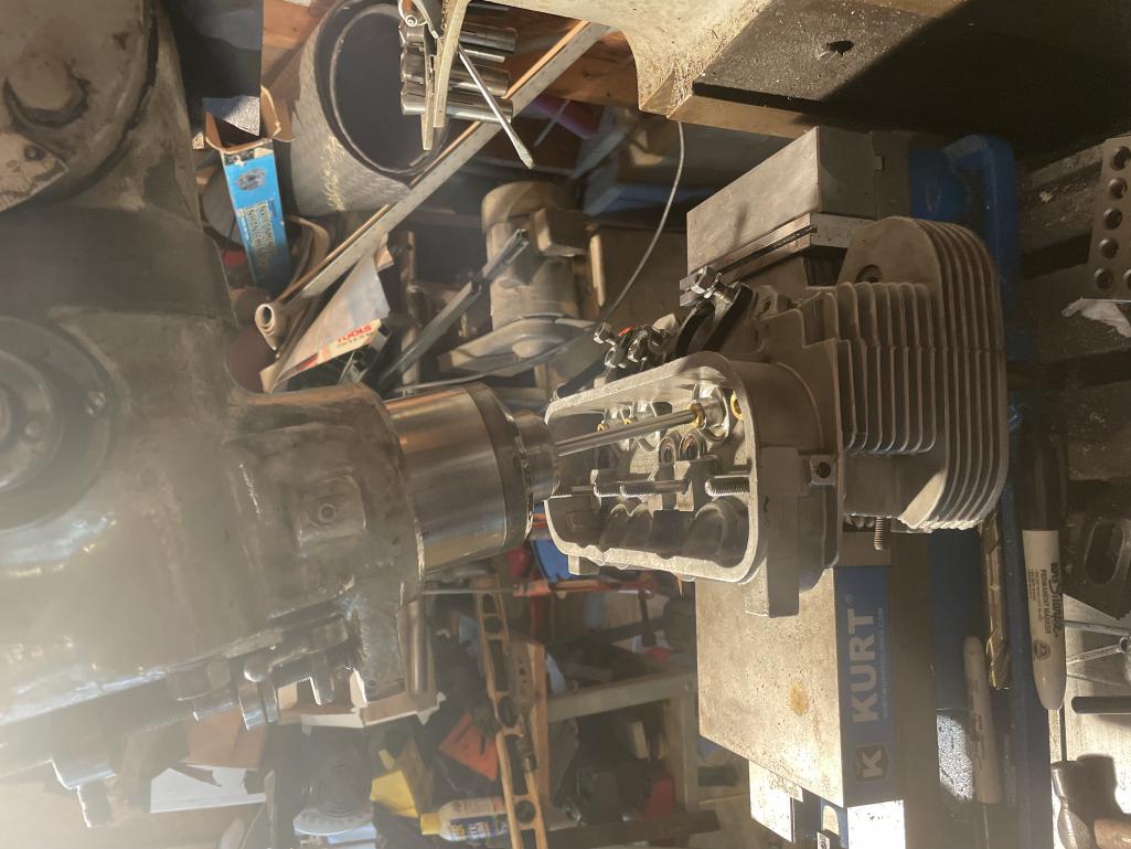
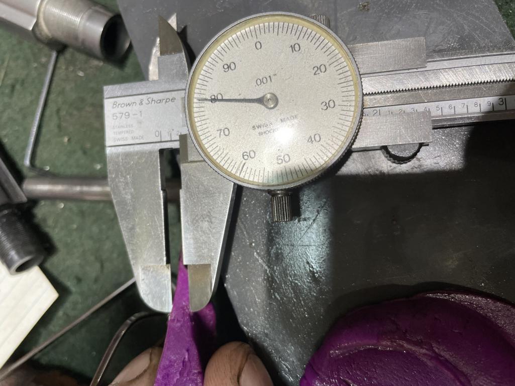
After the engine fail on my 2056 the investigation began measuring the piston the valve clearance. I tried the clay/ Playdoe method and the results were not as good as I would like. So i set up the failed Number 1 piston with the smiley (IMG:style_emoticons/default/smile.gif)
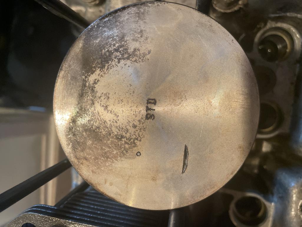 I set up the head from the other side without the bent valve and used the rocker shaft spring (just a light weight spring I had handy)to push down the valve till contact was made with the piston and the cam lobe was starting open the intake. At about 10 degrees on the degree wheel the closest reading was 0.080. ( this was in the small indentation made by the valve failure) I tilted the mill head to align with the valve guide and set the piston in the v blocks and used my 123 blocks to center the piston pin. I indexed the center of the intake valve with a pencil to set the Y axis on my Bridgeport. Centered on the mark, I now had to find the correct x axis. Since I already had the mark from the valve on the piston, I set the fly cutter .100 more than the diameter of the 44mm valve. The marked put the piston top was indexed and moved my X axis in to touch the previous valve mark. I then moved my X axis .050 inch and confirmed my zero to the cutter. I moved my Knee (set to zero) .050 inch to make the first cut. The piston crown of the KB measured at .220 ( for a min .170 thickness). This feels like a safe depth and puts my clearance at .130. I will repeat the process on the 2 valves notches with no "kiss' marks by marking up the piston tops with marker and using the valves to get the reference mark by hand |
   |

 
|
  |
Replies(1 - 19)
| rfinegan |
Oct 4 2021, 04:02 PM
Post
#2
|
|
Senior Member Group: Members Posts: 973 Joined: 8-February 13 From: NC Member No.: 15,499 Region Association: MidAtlantic Region |
mill angle
 |
|
|
|
| rfinegan |
Oct 4 2021, 04:10 PM
Post
#3
|
|
Senior Member Group: Members Posts: 973 Joined: 8-February 13 From: NC Member No.: 15,499 Region Association: MidAtlantic Region |
piston set up and fly cut to .050
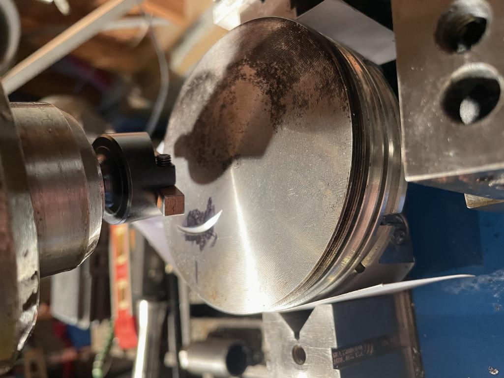 @ChrisFoley does this look right? Seem like a small notch compared to pistons that come with reliefs. But gives me the .130 I need All feedback welcome before I cut the other 3 intakes...I have a lot of clearance on the exhaust side .180 so no notch needed? |
|
|
|
| Dion |
Oct 4 2021, 04:11 PM
Post
#4
|
|
RN Group: Members Posts: 2,766 Joined: 16-September 04 From: Audubon,PA Member No.: 2,766 Region Association: MidAtlantic Region |
I wish I could fully understand what you just explained! It’s fascinating. Keep it coming.
Enjoying the education. (IMG:style_emoticons/default/beerchug.gif) |
|
|
|
| rfinegan |
Oct 4 2021, 04:31 PM
Post
#5
|
|
Senior Member Group: Members Posts: 973 Joined: 8-February 13 From: NC Member No.: 15,499 Region Association: MidAtlantic Region |
|
|
|
|
| rfinegan |
Oct 4 2021, 04:37 PM
Post
#6
|
|
Senior Member Group: Members Posts: 973 Joined: 8-February 13 From: NC Member No.: 15,499 Region Association: MidAtlantic Region |
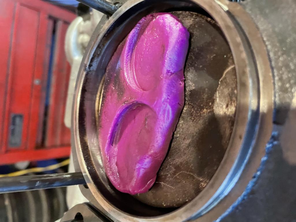
here is a pick of the play doe
 |
|
|
|
| rfinegan |
Oct 4 2021, 04:38 PM
Post
#7
|
|
Senior Member Group: Members Posts: 973 Joined: 8-February 13 From: NC Member No.: 15,499 Region Association: MidAtlantic Region |
exhaust valve clearance
 |
|
|
|
| Dion |
Oct 4 2021, 05:02 PM
Post
#8
|
|
RN Group: Members Posts: 2,766 Joined: 16-September 04 From: Audubon,PA Member No.: 2,766 Region Association: MidAtlantic Region |
@rfinegan Nope no problem with your writing. It’s just that I’m no engine builder.
I love this stuff . When Dave helped with my 2056 build a while ago, i found the process totally enjoyable. You have a great skill set. |
|
|
|
| rfinegan |
Oct 4 2021, 05:23 PM
Post
#9
|
|
Senior Member Group: Members Posts: 973 Joined: 8-February 13 From: NC Member No.: 15,499 Region Association: MidAtlantic Region |
set up
pic 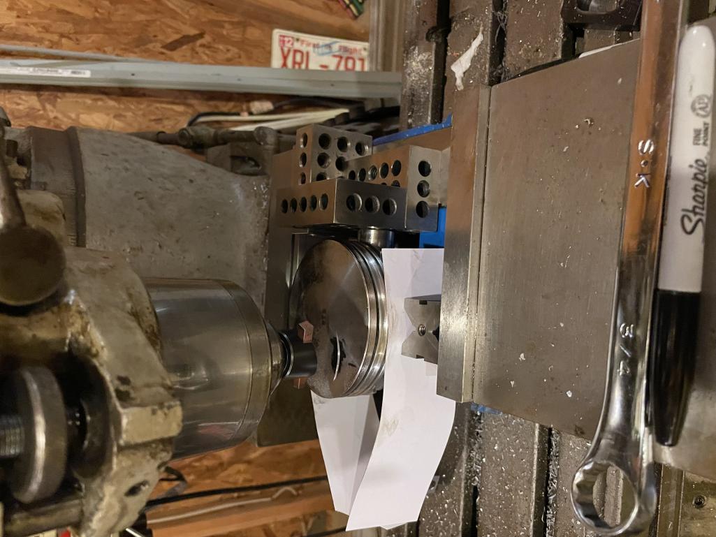 |
|
|
|
| Jamie |
Oct 4 2021, 05:33 PM
Post
#10
|
|
Senior Member Group: Members Posts: 1,032 Joined: 13-October 04 From: Georgetown,KY Member No.: 2,939 Region Association: South East States |
QUOTE(rfinegan @ Oct 4 2021, 03:23 PM)  set up pic The arc of the fly cut is a curve, but notice the ding in the old piston is flat across the base, like the face of the valve. I'm no machinist, but you need to cut a flat across the fly arc to give safe relief. (IMG:style_emoticons/default/aktion035.gif) |
|
|
|
| PatMc |
Oct 4 2021, 06:58 PM
Post
#11
|
|
Member Group: Members Posts: 120 Joined: 27-June 21 From: Long Beach Member No.: 25,669 Region Association: None |
QUOTE(Jamie @ Oct 4 2021, 06:33 PM) QUOTE(rfinegan @ Oct 4 2021, 03:23 PM) set up pic The arc of the fly cut is a curve, but notice the ding in the old piston is flat across the base, like the face of the valve. I'm no machinist, but you need to cut a flat across the fly arc to give safe relief. (IMG:style_emoticons/default/aktion035.gif) Without knowing the shape or relief in the cutting tool, it's tough to figure out what we're looking at. The cutting tool needs to effectively be a chunk of HSS with a radius slightly greater than the fillet radius on the valve. I think what we're seeing on the inside radius of that arc is where the brazed carbide stops, or it's not aligned with the tool shank...and it needs to be for this operation to work. I would personally just use a 1 7/8" endmill for this....but mostly since I happen to have one in the drawer. lol. |
|
|
|
| rfinegan |
Oct 5 2021, 03:46 AM
Post
#12
|
|
Senior Member Group: Members Posts: 973 Joined: 8-February 13 From: NC Member No.: 15,499 Region Association: MidAtlantic Region |
I see the problem now, I should have locked the Knee and cut with the quill. NOT the other way around. DOH!
I may have missed my mark. |
|
|
|
| rfinegan |
Oct 5 2021, 09:57 AM
Post
#13
|
|
Senior Member Group: Members Posts: 973 Joined: 8-February 13 From: NC Member No.: 15,499 Region Association: MidAtlantic Region |
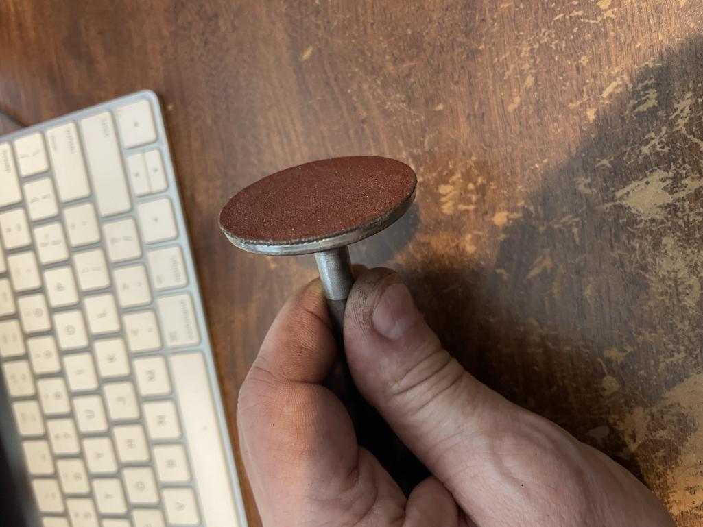
I made a valve notch cutter out of an Old AMC intake valve 1.97 and turned it down to 44 mm + .100 inch= 1.835 and radiused the outside edge. For the cutting I glued a 80 grit grinding disk to the valve face and trimmed to the diameter. One time use for each valve. Now I can cut just the intake pocket no need and have to drag across the piston to make a trough that is not needed
 |
|
|
|
| rfinegan |
Oct 5 2021, 10:01 AM
Post
#14
|
|
Senior Member Group: Members Posts: 973 Joined: 8-February 13 From: NC Member No.: 15,499 Region Association: MidAtlantic Region |
Practice cut look in good
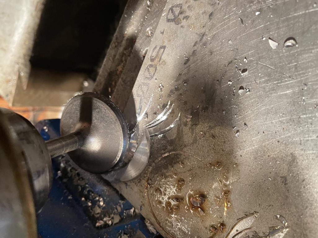 Now I just need to find the centerline of the valve guild (transfer at TDC with head and piston mock up) and a pencil down the valve guide. Then plunge cut with the Quill . Just like a valve opening or using the head as a guide to cut out the notches witha spinning valve. TO bad its the wrong stem and do not fit the heads With a bit of luck the previous notch may cut out? NO holding my breath. but 50 buck will get a new piston on the way if needed. I have to order the push rods any how' (IMG:style_emoticons/default/confused24.gif) |
|
|
|
| barefoot |
Oct 5 2021, 10:12 AM
Post
#15
|
|
Senior Member Group: Members Posts: 1,276 Joined: 19-March 13 From: Charleston SC Member No.: 15,673 Region Association: South East States |
QUOTE(rfinegan @ Oct 5 2021, 12:01 PM) Practice cut look in good Now I just need to find the centerline of the valve guild (transfer at TDC with head and piston mock up) and a pencil down the valve guide. Then plunge cut with the Quill . Just like a valve opening or using the head as a guide to cut out the notches witha spinning valve. TO bad its the wrong stem and do not fit the heads With a bit of luck the previous notch may cut out? NO holding my breath. but 50 buck will get a new piston on the way if needed. I have to order the push rods any how' (IMG:style_emoticons/default/confused24.gif) Or you could just re-assemble motor and use the actual valve guide in the head and an electric drill to rotate your abrasive coated valve, would be quick & accurate. Just insure no swarf gets down to the rings |
|
|
|
| mmichalik |
Oct 5 2021, 10:20 AM
Post
#16
|
|
MikeM Group: Members Posts: 700 Joined: 27-January 16 From: Valley Center, CA Member No.: 19,600 Region Association: Southern California |
I'm absolutely fascinated by all of this and wish I could follow it. It's so beyond my skill set right now, I just stare at everything and say to myself "ummmm, duhhhhhhh"
(IMG:style_emoticons/default/smile.gif) Thank you for posting it. It really gets me thinking. |
|
|
|
| rfinegan |
Oct 5 2021, 11:04 AM
Post
#17
|
|
Senior Member Group: Members Posts: 973 Joined: 8-February 13 From: NC Member No.: 15,499 Region Association: MidAtlantic Region |
@Barefoot problems with useing the heads:
1) 2 of my intake valve guides are damaged by the bent valves and had top beat the valves out of the guilds. 2) The "Larger" +.100 AMC cutters are the wrong stem size (Too big) and do not wish to wait till the heads are repaired and tear them apart to use as grinding jigs. Turn them down to fit? Not worth the risk to damaging the good (NEW guides) GOOD tips...Thanks -Robert QUOTE(barefoot @ Oct 5 2021, 08:12 AM) QUOTE(rfinegan @ Oct 5 2021, 12:01 PM) Practice cut look in good Now I just need to find the centerline of the valve guild (transfer at TDC with head and piston mock up) and a pencil down the valve guide. Then plunge cut with the Quill . Just like a valve opening or using the head as a guide to cut out the notches witha spinning valve. TO bad its the wrong stem and do not fit the heads With a bit of luck the previous notch may cut out? NO holding my breath. but 50 buck will get a new piston on the way if needed. I have to order the push rods any how' (IMG:style_emoticons/default/confused24.gif) Or you could just re-assemble motor and use the actual valve guide in the head and an electric drill to rotate your abrasive coated valve, would be quick & accurate. Just insure no swarf gets down to the rings |
|
|
|
| rfinegan |
Oct 5 2021, 01:30 PM
Post
#18
|
|
Senior Member Group: Members Posts: 973 Joined: 8-February 13 From: NC Member No.: 15,499 Region Association: MidAtlantic Region |
I am going to walk through this process One MORE TIME! Well I get to do it 4 times for the intakes( and 4 for the exhaust if needed)
1)Remove valves from head and assemble with torque spec 2)Rotate crankshaft to TDC (see degree wheel ) 3)Insert pencil to mark centerline of valve on top of piston 4)Center punch center line location for Posterity 5) Using V blocks mount piston to vice with business cards to protect a) Use the piston pin to parallel blocks ensure the piston in pin is perpendicular to the vice 6) Center the Quill to the reference valve center line in piston and lock the X/Y tables 7) Insert cutter in collet and check location for cut 8) Plunge cut with short pecking motion to cut valve relief notch to desired depth ( used .050") It does not look like much of a notch but the .080 valve clearance I had, Plus the .050 clear once cut should yield a toll clearance of 0.130 on the intake HELP NEEDED: How deep can I safely cut may valve notch before the crown is too thin? The Keith black 96 pistons seem to measure a crown thickness of 0.220 and removing .050 gives me the minimum thickness of. 0.170 I am worried I need to take a deeper cut as the valve may have been in the mechanical notch made when the piston Kissed. Sure I will measure again and once more when the heads are done but would be nice to cut this one to depth and me to the next one |
|
|
|
| rfinegan |
Oct 5 2021, 02:04 PM
Post
#19
|
|
Senior Member Group: Members Posts: 973 Joined: 8-February 13 From: NC Member No.: 15,499 Region Association: MidAtlantic Region |
I just got off the phone with UEM the manufacture of the KB 96 pistons for the 2056 at EMW (only). They confirmed the min crown of 0.160 is a good place to respect and will be OK. So all good...
Here are some pics of the Process ... Location of the Centerline of the Intake valves at TDC 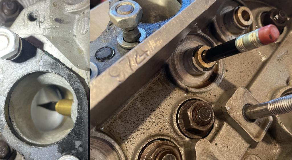 |
|
|
|
| rfinegan |
Oct 5 2021, 02:06 PM
Post
#20
|
|
Senior Member Group: Members Posts: 973 Joined: 8-February 13 From: NC Member No.: 15,499 Region Association: MidAtlantic Region |
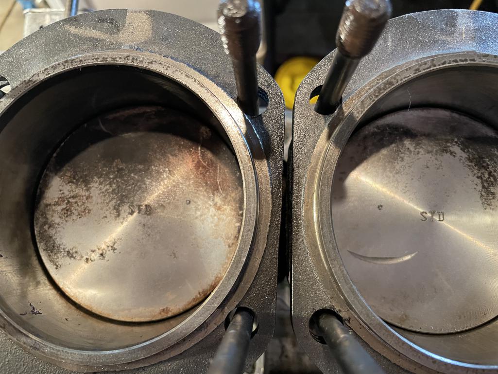
center punched locators on piston tops
 |
|
|
|
|
1 User(s) are reading this topic (1 Guests and 0 Anonymous Users)
0 Members:

|
Lo-Fi Version | Time is now: 26th May 2024 - 08:57 AM |
Invision Power Board
v9.1.4 © 2024 IPS, Inc.