|
|
|
Porsche, and the Porsche crest are registered trademarks of Dr. Ing. h.c. F. Porsche AG.
This site is not affiliated with Porsche in any way. Its only purpose is to provide an online forum for car enthusiasts. All other trademarks are property of their respective owners. |
|
|


| Puebloswatcop |
 Oct 6 2021, 05:31 PM Oct 6 2021, 05:31 PM
Post
#41
|
|
Senior Member  Group: Members Posts: 1,708 Joined: 27-December 14 From: Mineola, Texas Member No.: 18,258 Region Association: Southwest Region |
(IMG:style_emoticons/default/piratenanner.gif) So I finally got the first of the two Texas Twins down from Colorado down here to Texas and cant wait to get started on the build. I first obtained this 914 as a parts car back in 2010. After getting it home, I realized it was actually in better shape than the one I already owned. The first one is a 1973, 2.0. This one was a 1974 1.8 in Ravenna Green. Unfortunately I never was able to make allot of time to play with the car, so it sat in my overcrowded garage in Colorado.
Since I retired and moved to Texas, the wife said I had better find something to do and stay out from under her feet, so last week I made the treck to Colorado and brought the first of 3 914s back. (the 3rd really is a parts chassis). The car was on a rolling frame so was easy to get onto the trailer, problem is it had to be lowered enough to fit inside a four foot cover to be added onto the trailer, so first we had to raise it high enough to get it off the rolling frame. 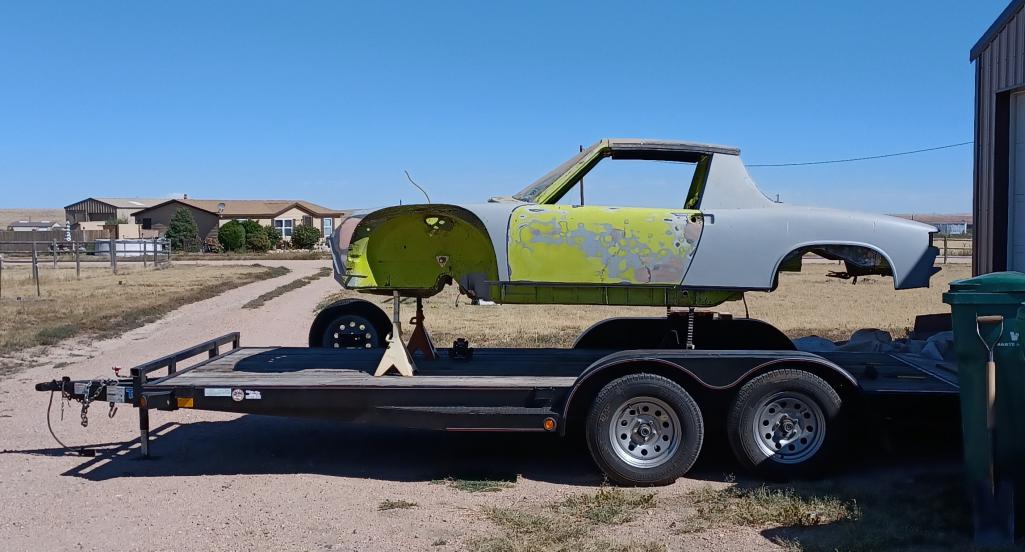 Then it had to be carefully lowered to where the car was sitting on 4 X 4 blocks so it would be lower than 4 feet high and secured to the trailer. It came in at around 3'8" when done. 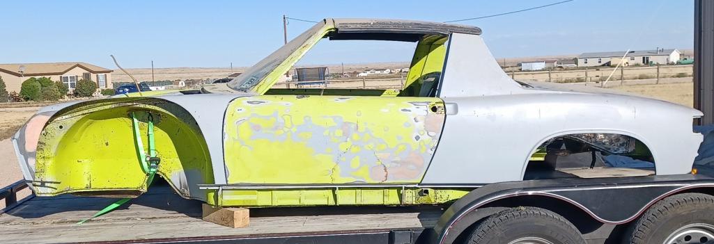 Then the shipping crate was built over and around the car. The trip was long and went well till I got about 10 miles from home and disaster struck.  A catastrphic loss of one tire on the trailer. Thanks to a good samaritan who flagged me down, because I never heard or felt a thing. Also a testament to Top Hat Trailer Company, the trailer was slightly damaged but did not roll, in fact it rode so smooth that I never new the tire had gone away. Of course...no spare for the trailer, so I limped the last 10 miles at 15 miles per hour.  So 16 hours of driving and now one of my babies is here in Texas and the work shall begin. |
   |

 
|
Posts in this topic
Puebloswatcop First of the Texas Twins Oct 6 2021, 05:31 PM 9146C Happy to hear you're about to start your proje... Oct 6 2021, 05:44 PM Jamie
:Qarl: So I finally got the first of the two Texa... Oct 6 2021, 06:50 PM
9146C Happy to hear you're about to start your proje... Oct 6 2021, 05:44 PM Jamie
:Qarl: So I finally got the first of the two Texa... Oct 6 2021, 06:50 PM
 Puebloswatcop
:Qarl: So I finally got the first of the two Tex... Oct 7 2021, 06:27 AM Literati914 Awesome, gonna be more 914s in the DFW area! I... Oct 6 2021, 07:08 PM nivekdodge isn't that a spare in the fist pic? Oct 6 2021, 07:51 PM ClayPerrine :wttc:
There is a large contingent of 914 people... Oct 7 2021, 06:00 AM Shivers Glad you made it safe. Welcome Oct 7 2021, 06:24 AM Puebloswatcop Wow,
I did not know there were as many 914ers in... Oct 7 2021, 06:36 AM Cairo94507 Glad you made it OK, but come on brother, put a fu... Oct 7 2021, 07:10 AM Puebloswatcop
Glad you made it OK, but come on brother, put a f... Oct 7 2021, 09:27 AM PanelBilly I know this must have been a lot of trauma for you... Oct 7 2021, 09:38 AM Puebloswatcop So now that I made it to Texas, It was time to unl... Oct 7 2021, 09:50 AM 76-914 Great story and a great new location. Is that Amer... Oct 7 2021, 10:02 AM Puebloswatcop
Great story and a great new location. Is that Ame... Oct 7 2021, 12:28 PM Root_Werks Great story and adventure, can't wait to see t... Oct 7 2021, 11:20 AM Puebloswatcop :wacko: So spent the day unpacking a truckload of ... Oct 7 2021, 02:37 PM Puebloswatcop Spent the remainder of yesterday removing the laye... Oct 8 2021, 09:28 AM Puebloswatcop The headlight buckets are in pretty good shape. T... Oct 8 2021, 09:33 AM Puebloswatcop Front Trunk isnt to bad, some rust that isnt to de... Oct 8 2021, 09:33 AM Puebloswatcop The original Body Tag is still attached to the rig... Oct 8 2021, 09:45 AM Puebloswatcop And of course the channel corners where the cowel ... Oct 8 2021, 09:48 AM Puebloswatcop The firewall and gas tank area are in great shape
... Oct 8 2021, 09:53 AM Puebloswatcop The interior front half of the floor is in remarka... Oct 8 2021, 10:03 AM Puebloswatcop The rear floor half has been replaced, but still h... Oct 8 2021, 10:09 AM Puebloswatcop The rear wall on the drivers side is solid, the pa... Oct 8 2021, 11:40 AM Puebloswatcop The drivers door leaves a bit to be desired. The ... Oct 8 2021, 11:51 AM Puebloswatcop Passenger door is good except for the speaker hole... Oct 8 2021, 11:54 AM Puebloswatcop The engine compartment was a mess when I first got... Oct 8 2021, 12:06 PM Puebloswatcop Further inspection up under the drivers side fende... Oct 8 2021, 12:18 PM Puebloswatcop Inside the right rear fender well, you can see the... Oct 8 2021, 12:23 PM Puebloswatcop The rear trunk is good and solid, however the moun... Oct 8 2021, 12:35 PM Puebloswatcop The right side fender flares have already been pla... Oct 8 2021, 12:43 PM Puebloswatcop So today is NASCAR race day so just killing some t... Oct 10 2021, 11:07 AM Puebloswatcop After getting the tank dismantled I found that the... Oct 10 2021, 11:13 AM Puebloswatcop The inside of the tank is not pristine, but looks ... Oct 10 2021, 11:18 AM Jamie
The inside of the tank is not pristine, but looks... Oct 10 2021, 08:10 PM Puebloswatcop
The inside of the tank is not pristine, but look... Oct 12 2021, 03:53 PM Puebloswatcop Any Advice on the best way to remove the windshiel... Oct 12 2021, 03:52 PM Puebloswatcop
Any Advice on the best way to remove the windshie... Oct 12 2021, 07:28 PM pete000 Nice rescue ! have fun love the color ! :... Oct 13 2021, 10:35 AM Puebloswatcop
Nice rescue ! have fun love the color ! ... Oct 14 2021, 02:22 PM Puebloswatcop So, with rain on and off today, I couldnt move the... Oct 14 2021, 02:39 PM Puebloswatcop Then I decided to start working on the steering co... Oct 14 2021, 02:57 PM Puebloswatcop The deeper I got, I found the crud just continued.... Oct 14 2021, 03:03 PM Puebloswatcop So, as I suspected the upper bearing is shot, feel... Oct 15 2021, 03:34 PM Literati914 Dang.. nice jobs with that :beer1:
I wasn't ... Oct 15 2021, 06:41 PM oldie914 You might consider using generic bearings instead ... Oct 16 2021, 05:17 AM Puebloswatcop
You might consider using generic bearings instead... Oct 16 2021, 06:32 AM Puebloswatcop So today it was nice enough to park the hot rod ou... Oct 19 2021, 07:57 PM Puebloswatcop Then moved on to the rust along the drivers side f... Oct 19 2021, 08:20 PM Puebloswatcop Since I couldn't figure out the welder I moved... Oct 19 2021, 08:26 PM Puebloswatcop Okay, so after spending over an hour this morning ... Oct 20 2021, 04:50 PM Literati914 Nice job, keep it up..
. Oct 20 2021, 06:59 PM Puebloswatcop Got the support metal ground down and primed
Th... Oct 22 2021, 08:16 AM tygaboy Excellent fab work! :headbanger: Oct 22 2021, 09:37 AM 9146C Very nice work Kevin!
The finished product is... Oct 22 2021, 09:45 AM Puebloswatcop So today I decided to take the day off from body w... Oct 22 2021, 04:01 PM Puebloswatcop After laying everything out, I decided to start by... Oct 22 2021, 04:24 PM Puebloswatcop From there i moved on to the ignition switch repla... Oct 22 2021, 04:49 PM Puebloswatcop Since I plan on changing from a stock steering whe... Oct 22 2021, 05:03 PM autopro I wasn't aware of that wiper switch modificati... Oct 22 2021, 05:23 PM Puebloswatcop
I wasn't aware of that wiper switch modificat... Oct 22 2021, 06:21 PM Puebloswatcop After completing the sub assemblies, I began assem... Oct 22 2021, 05:42 PM Puebloswatcop Then it was time to re-install all of the guts. F... Oct 22 2021, 06:10 PM Puebloswatcop I forgot how much I love chipping the spray on und... Oct 24 2021, 11:39 AM Puebloswatcop Spent most of the day sand blasting miscellaneous ... Oct 25 2021, 07:02 PM Puebloswatcop Today I decided to work on the engine compartment ... Oct 26 2021, 06:37 PM Puebloswatcop Then I went to work on the engine lid. I started ... Oct 26 2021, 06:42 PM Puebloswatcop Then I drilled holes to mirror the regular screen ... Oct 26 2021, 06:47 PM Puebloswatcop Then after spending the better part of an hour gri... Oct 26 2021, 06:54 PM Puebloswatcop After getting what I though was a fairly good fit,... Oct 26 2021, 07:01 PM Puebloswatcop Today started off by identifying any PO drilled ho... Oct 27 2021, 06:42 PM bkrantz
Today started off by identifying any PO drilled h... Oct 27 2021, 08:00 PM Puebloswatcop
Today started off by identifying any PO drilled ... Oct 28 2021, 07:29 AM Puebloswatcop I began by forming a piece to fill the larger hole... Oct 27 2021, 06:43 PM Puebloswatcop Then welded it all up to include the small hole be... Oct 27 2021, 06:51 PM Puebloswatcop Then I removed the body filler that was in the low... Oct 27 2021, 06:57 PM Puebloswatcop And with that I decided I was tired of trying to c... Oct 27 2021, 07:02 PM Puebloswatcop Decided to take a break from working on the body t... Nov 1 2021, 08:38 AM Puebloswatcop The next thing I unboxed was the climate controls.... Nov 1 2021, 08:52 AM Puebloswatcop One thing I did find is that it appears there is a... Nov 1 2021, 08:56 AM Puebloswatcop So I spent about an hour dis-assembling parts of t... Nov 1 2021, 08:59 AM Puebloswatcop Then re-assebled the clean product. Everything se... Nov 1 2021, 09:02 AM Puebloswatcop Cleaned up the passenger side B pillar trim, could... Nov 1 2021, 09:11 AM Puebloswatcop Then cleaned and checked the center console. Hook... Nov 1 2021, 09:14 AM Puebloswatcop To finish up the weekend, I cleaned the entire gua... Nov 1 2021, 09:17 AM Cornerlot Welcome to Texas. I had to look up Mineola, wasn... Nov 1 2021, 10:11 AM Puebloswatcop
Welcome to Texas. I had to look up Mineola, wasn... Nov 1 2021, 02:02 PM Puebloswatcop Since today was a rainy and cold I decided to lift... Nov 3 2021, 03:23 PM Puebloswatcop Only had 20 inches to get it onto the mounts
Nov 3 2021, 03:25 PM Puebloswatcop Then after getting it onto the rotisserie had to r... Nov 3 2021, 03:27 PM Puebloswatcop And some 5 hours after starting, Its finally on th... Nov 3 2021, 03:30 PM bkrantz
And some 5 hours after starting, Its finally on t... Nov 3 2021, 07:18 PM Puebloswatcop
And some 5 hours after starting, Its finally on ... Nov 4 2021, 07:43 AM Literati914 I feel ya on this.. I did kinda the same song and ... Nov 3 2021, 04:38 PM Puebloswatcop
I feel ya on this.. I did kinda the same song and... Nov 4 2021, 04:38 PM Puebloswatcop So today was spent stripping the undercoating from... Nov 4 2021, 04:41 PM Puebloswatcop At least some of it was already done, but there ar... Nov 4 2021, 04:44 PM Puebloswatcop The good thing is the engine compartment is pretty... Nov 4 2021, 04:47 PM
Puebloswatcop
:Qarl: So I finally got the first of the two Tex... Oct 7 2021, 06:27 AM Literati914 Awesome, gonna be more 914s in the DFW area! I... Oct 6 2021, 07:08 PM nivekdodge isn't that a spare in the fist pic? Oct 6 2021, 07:51 PM ClayPerrine :wttc:
There is a large contingent of 914 people... Oct 7 2021, 06:00 AM Shivers Glad you made it safe. Welcome Oct 7 2021, 06:24 AM Puebloswatcop Wow,
I did not know there were as many 914ers in... Oct 7 2021, 06:36 AM Cairo94507 Glad you made it OK, but come on brother, put a fu... Oct 7 2021, 07:10 AM Puebloswatcop
Glad you made it OK, but come on brother, put a f... Oct 7 2021, 09:27 AM PanelBilly I know this must have been a lot of trauma for you... Oct 7 2021, 09:38 AM Puebloswatcop So now that I made it to Texas, It was time to unl... Oct 7 2021, 09:50 AM 76-914 Great story and a great new location. Is that Amer... Oct 7 2021, 10:02 AM Puebloswatcop
Great story and a great new location. Is that Ame... Oct 7 2021, 12:28 PM Root_Werks Great story and adventure, can't wait to see t... Oct 7 2021, 11:20 AM Puebloswatcop :wacko: So spent the day unpacking a truckload of ... Oct 7 2021, 02:37 PM Puebloswatcop Spent the remainder of yesterday removing the laye... Oct 8 2021, 09:28 AM Puebloswatcop The headlight buckets are in pretty good shape. T... Oct 8 2021, 09:33 AM Puebloswatcop Front Trunk isnt to bad, some rust that isnt to de... Oct 8 2021, 09:33 AM Puebloswatcop The original Body Tag is still attached to the rig... Oct 8 2021, 09:45 AM Puebloswatcop And of course the channel corners where the cowel ... Oct 8 2021, 09:48 AM Puebloswatcop The firewall and gas tank area are in great shape
... Oct 8 2021, 09:53 AM Puebloswatcop The interior front half of the floor is in remarka... Oct 8 2021, 10:03 AM Puebloswatcop The rear floor half has been replaced, but still h... Oct 8 2021, 10:09 AM Puebloswatcop The rear wall on the drivers side is solid, the pa... Oct 8 2021, 11:40 AM Puebloswatcop The drivers door leaves a bit to be desired. The ... Oct 8 2021, 11:51 AM Puebloswatcop Passenger door is good except for the speaker hole... Oct 8 2021, 11:54 AM Puebloswatcop The engine compartment was a mess when I first got... Oct 8 2021, 12:06 PM Puebloswatcop Further inspection up under the drivers side fende... Oct 8 2021, 12:18 PM Puebloswatcop Inside the right rear fender well, you can see the... Oct 8 2021, 12:23 PM Puebloswatcop The rear trunk is good and solid, however the moun... Oct 8 2021, 12:35 PM Puebloswatcop The right side fender flares have already been pla... Oct 8 2021, 12:43 PM Puebloswatcop So today is NASCAR race day so just killing some t... Oct 10 2021, 11:07 AM Puebloswatcop After getting the tank dismantled I found that the... Oct 10 2021, 11:13 AM Puebloswatcop The inside of the tank is not pristine, but looks ... Oct 10 2021, 11:18 AM Jamie
The inside of the tank is not pristine, but looks... Oct 10 2021, 08:10 PM Puebloswatcop
The inside of the tank is not pristine, but look... Oct 12 2021, 03:53 PM Puebloswatcop Any Advice on the best way to remove the windshiel... Oct 12 2021, 03:52 PM Puebloswatcop
Any Advice on the best way to remove the windshie... Oct 12 2021, 07:28 PM pete000 Nice rescue ! have fun love the color ! :... Oct 13 2021, 10:35 AM Puebloswatcop
Nice rescue ! have fun love the color ! ... Oct 14 2021, 02:22 PM Puebloswatcop So, with rain on and off today, I couldnt move the... Oct 14 2021, 02:39 PM Puebloswatcop Then I decided to start working on the steering co... Oct 14 2021, 02:57 PM Puebloswatcop The deeper I got, I found the crud just continued.... Oct 14 2021, 03:03 PM Puebloswatcop So, as I suspected the upper bearing is shot, feel... Oct 15 2021, 03:34 PM Literati914 Dang.. nice jobs with that :beer1:
I wasn't ... Oct 15 2021, 06:41 PM oldie914 You might consider using generic bearings instead ... Oct 16 2021, 05:17 AM Puebloswatcop
You might consider using generic bearings instead... Oct 16 2021, 06:32 AM Puebloswatcop So today it was nice enough to park the hot rod ou... Oct 19 2021, 07:57 PM Puebloswatcop Then moved on to the rust along the drivers side f... Oct 19 2021, 08:20 PM Puebloswatcop Since I couldn't figure out the welder I moved... Oct 19 2021, 08:26 PM Puebloswatcop Okay, so after spending over an hour this morning ... Oct 20 2021, 04:50 PM Literati914 Nice job, keep it up..
. Oct 20 2021, 06:59 PM Puebloswatcop Got the support metal ground down and primed
Th... Oct 22 2021, 08:16 AM tygaboy Excellent fab work! :headbanger: Oct 22 2021, 09:37 AM 9146C Very nice work Kevin!
The finished product is... Oct 22 2021, 09:45 AM Puebloswatcop So today I decided to take the day off from body w... Oct 22 2021, 04:01 PM Puebloswatcop After laying everything out, I decided to start by... Oct 22 2021, 04:24 PM Puebloswatcop From there i moved on to the ignition switch repla... Oct 22 2021, 04:49 PM Puebloswatcop Since I plan on changing from a stock steering whe... Oct 22 2021, 05:03 PM autopro I wasn't aware of that wiper switch modificati... Oct 22 2021, 05:23 PM Puebloswatcop
I wasn't aware of that wiper switch modificat... Oct 22 2021, 06:21 PM Puebloswatcop After completing the sub assemblies, I began assem... Oct 22 2021, 05:42 PM Puebloswatcop Then it was time to re-install all of the guts. F... Oct 22 2021, 06:10 PM Puebloswatcop I forgot how much I love chipping the spray on und... Oct 24 2021, 11:39 AM Puebloswatcop Spent most of the day sand blasting miscellaneous ... Oct 25 2021, 07:02 PM Puebloswatcop Today I decided to work on the engine compartment ... Oct 26 2021, 06:37 PM Puebloswatcop Then I went to work on the engine lid. I started ... Oct 26 2021, 06:42 PM Puebloswatcop Then I drilled holes to mirror the regular screen ... Oct 26 2021, 06:47 PM Puebloswatcop Then after spending the better part of an hour gri... Oct 26 2021, 06:54 PM Puebloswatcop After getting what I though was a fairly good fit,... Oct 26 2021, 07:01 PM Puebloswatcop Today started off by identifying any PO drilled ho... Oct 27 2021, 06:42 PM bkrantz
Today started off by identifying any PO drilled h... Oct 27 2021, 08:00 PM Puebloswatcop
Today started off by identifying any PO drilled ... Oct 28 2021, 07:29 AM Puebloswatcop I began by forming a piece to fill the larger hole... Oct 27 2021, 06:43 PM Puebloswatcop Then welded it all up to include the small hole be... Oct 27 2021, 06:51 PM Puebloswatcop Then I removed the body filler that was in the low... Oct 27 2021, 06:57 PM Puebloswatcop And with that I decided I was tired of trying to c... Oct 27 2021, 07:02 PM Puebloswatcop Decided to take a break from working on the body t... Nov 1 2021, 08:38 AM Puebloswatcop The next thing I unboxed was the climate controls.... Nov 1 2021, 08:52 AM Puebloswatcop One thing I did find is that it appears there is a... Nov 1 2021, 08:56 AM Puebloswatcop So I spent about an hour dis-assembling parts of t... Nov 1 2021, 08:59 AM Puebloswatcop Then re-assebled the clean product. Everything se... Nov 1 2021, 09:02 AM Puebloswatcop Cleaned up the passenger side B pillar trim, could... Nov 1 2021, 09:11 AM Puebloswatcop Then cleaned and checked the center console. Hook... Nov 1 2021, 09:14 AM Puebloswatcop To finish up the weekend, I cleaned the entire gua... Nov 1 2021, 09:17 AM Cornerlot Welcome to Texas. I had to look up Mineola, wasn... Nov 1 2021, 10:11 AM Puebloswatcop
Welcome to Texas. I had to look up Mineola, wasn... Nov 1 2021, 02:02 PM Puebloswatcop Since today was a rainy and cold I decided to lift... Nov 3 2021, 03:23 PM Puebloswatcop Only had 20 inches to get it onto the mounts
Nov 3 2021, 03:25 PM Puebloswatcop Then after getting it onto the rotisserie had to r... Nov 3 2021, 03:27 PM Puebloswatcop And some 5 hours after starting, Its finally on th... Nov 3 2021, 03:30 PM bkrantz
And some 5 hours after starting, Its finally on t... Nov 3 2021, 07:18 PM Puebloswatcop
And some 5 hours after starting, Its finally on ... Nov 4 2021, 07:43 AM Literati914 I feel ya on this.. I did kinda the same song and ... Nov 3 2021, 04:38 PM Puebloswatcop
I feel ya on this.. I did kinda the same song and... Nov 4 2021, 04:38 PM Puebloswatcop So today was spent stripping the undercoating from... Nov 4 2021, 04:41 PM Puebloswatcop At least some of it was already done, but there ar... Nov 4 2021, 04:44 PM Puebloswatcop The good thing is the engine compartment is pretty... Nov 4 2021, 04:47 PM  |
1 User(s) are reading this topic (1 Guests and 0 Anonymous Users)
0 Members:

|
Lo-Fi Version | Time is now: 26th July 2026 - 04:54 PM |
Invision Power Board
v9.1.4 © 2026 IPS, Inc.