|
|
|
Porsche, and the Porsche crest are registered trademarks of Dr. Ing. h.c. F. Porsche AG.
This site is not affiliated with Porsche in any way. Its only purpose is to provide an online forum for car enthusiasts. All other trademarks are property of their respective owners. |
|
|

 Model Specific Information
914/4: 70 71 72 73 74 75 76 914/6: 70 71 72
  |

| wonkipop |
 Oct 29 2025, 11:23 PM Oct 29 2025, 11:23 PM
Post
#281
|
|
914 Guru  Group: Members Posts: 5,573 Joined: 6-May 20 From: north antarctica Member No.: 24,231 Region Association: NineFourteenerVille |
ENGINE BAY BLOWER FAN.
On the data collected to date it appears the engine bay blower fan set up was updated during the course of MY 1975. examples dating from 08/74, 09/74, 10/74 & 11/74 retain the single hose blower fan with a hose feeding to the left hand side heat exchanger only that was used for the 1974 MY. 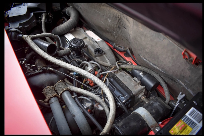 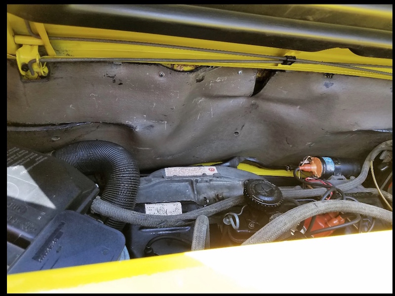 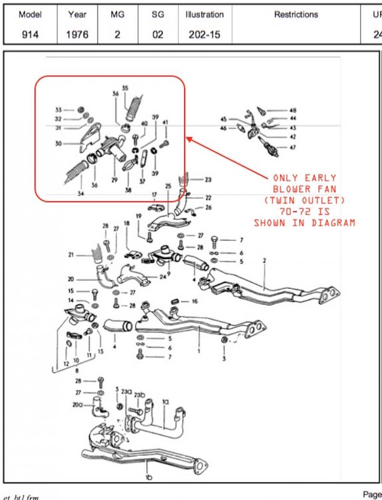 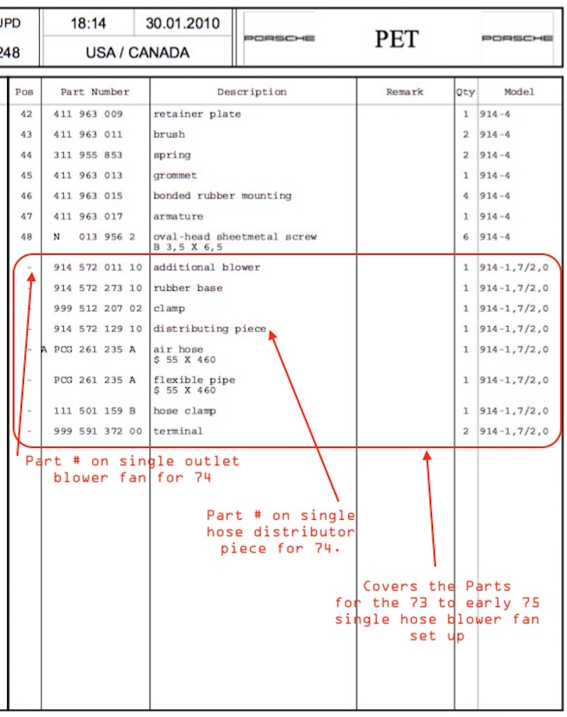 examples dating from 12/74 and on to end of MY production used a revised twin hose blower fan with dual hoses feeding to both the left and right side heat exchangers. the adaptor piece attached to the fan unit appears (based on an extant original example) to have been a VW part used on the 411/412 variant. 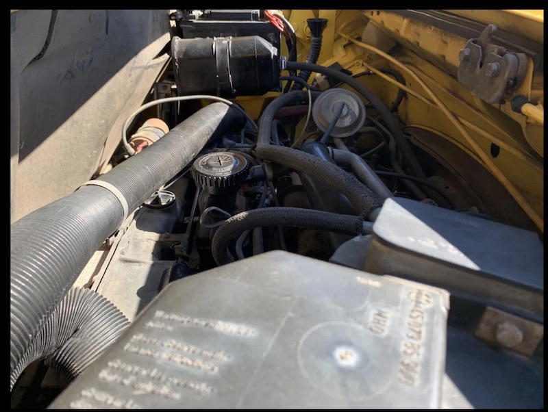 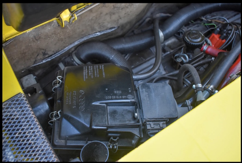   data collected points to a changeover date late nov 74 or early dec 74. |
   |

 
|
| wonkipop |
Oct 29 2025, 11:30 PM
Post
#282
|
|
914 Guru Group: Members Posts: 5,573 Joined: 6-May 20 From: north antarctica Member No.: 24,231 Region Association: NineFourteenerVille |
EVAPORATIVE EMISSIONS SET UP.
it has previously been determined that VW & Porsche revised the hose connection set up to the charcoal cannister at the time the cannister was moved to a location on the rear firewall of the engine compartment from its previous location in the front trunk. this ocurred during approx the third week of nov 1973. refer to pg 3 of this topic where the emissions warranties and associated schematic diagrams are traced from 73 MY to 76 MY. the 1975 1.8 L Jetronics used the same hose connection schema as the 74 L jets. the charcoal cannister was repositioned in 1975 directly adjacent to the battery tray. this was possibly done to facilitate space for the EGR valve and plumbing for the california market EF-16 and standardized across both engines.  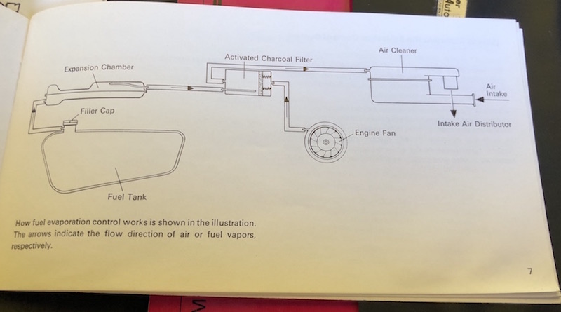 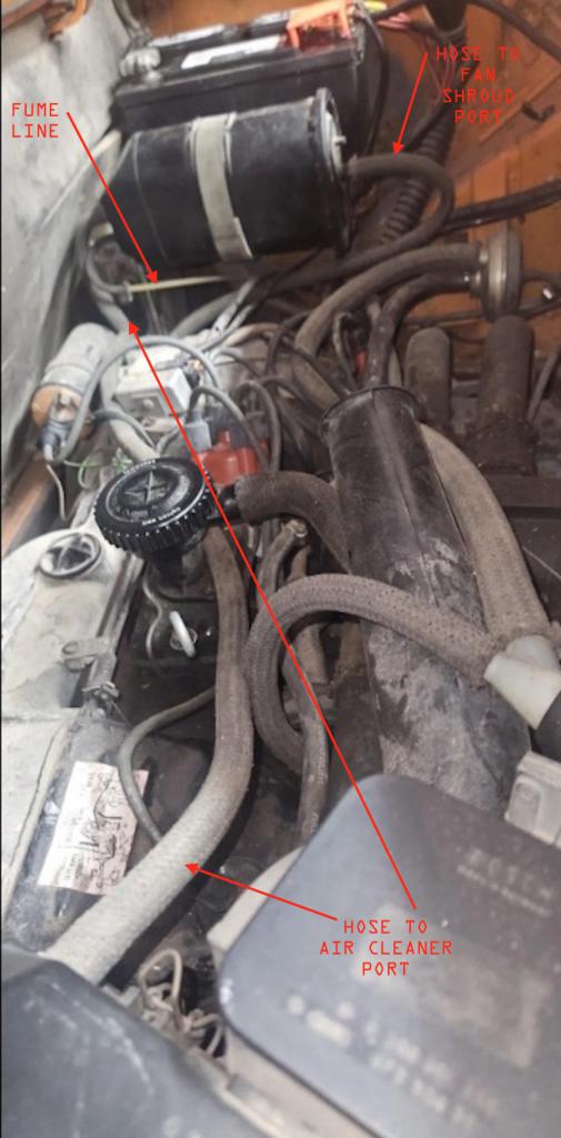 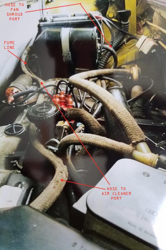 |
|
|
|
| wonkipop |
Oct 29 2025, 11:32 PM
Post
#283
|
|
914 Guru Group: Members Posts: 5,573 Joined: 6-May 20 From: north antarctica Member No.: 24,231 Region Association: NineFourteenerVille |
EF-15 & EF-16 VACUUM HOSE DIAGRAMS
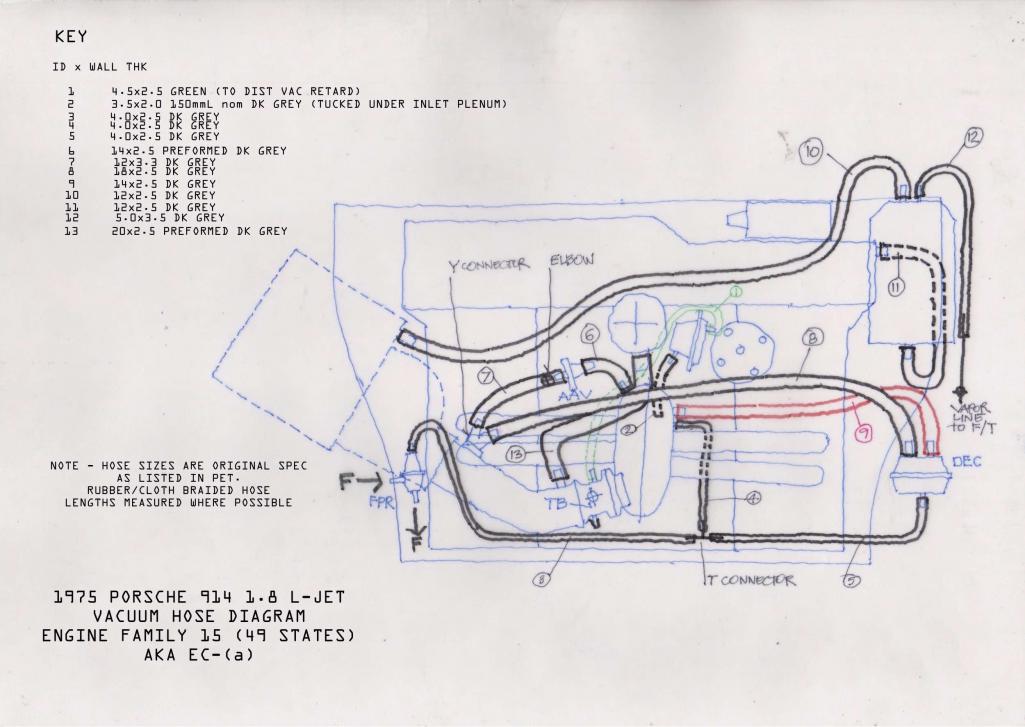 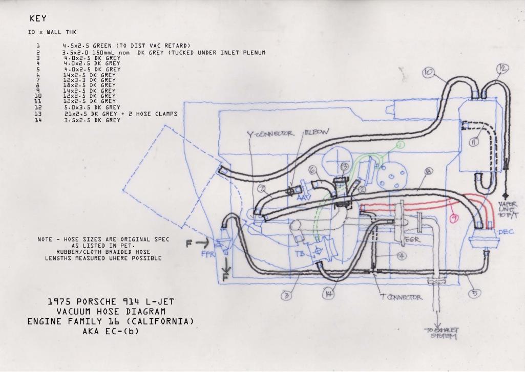 Refer to page 3 of this topic for the vacuum hose diagrams for the 1974 L-Jet EC-A and EC-B engines previously published here in 2022. @JeffBowlsby - here are your vac hose diagrams for the 75 L Jets. sorry for the 3 year delay but it took that long to accumulate data that i could trust before i did them. (IMG:style_emoticons/default/biggrin.gif) + i am enjoying a nice lull in arch activities and its spring time - and i felt like drawing. dusted off the drawing board and put away the computer. i sometimes wonder if technology has really taken us into a future whenever i get my old paraline out and a packet of felt tip pens. (IMG:style_emoticons/default/beerchug.gif) |
|
|
|
|
2 User(s) are reading this topic (2 Guests and 0 Anonymous Users)
0 Members:

|
Lo-Fi Version | Time is now: 26th June 2026 - 12:46 PM |
Invision Power Board
v9.1.4 © 2026 IPS, Inc.