|
|
|
Porsche, and the Porsche crest are registered trademarks of Dr. Ing. h.c. F. Porsche AG.
This site is not affiliated with Porsche in any way. Its only purpose is to provide an online forum for car enthusiasts. All other trademarks are property of their respective owners. |
|
|


| pbanders |
 May 20 2022, 04:58 PM May 20 2022, 04:58 PM
Post
#1
|
|
Senior Member  Group: Members Posts: 939 Joined: 11-June 03 From: Phoenix, AZ Member No.: 805 |
I always learn something when I see other people's engine bay pics, so I thought I'd start a topic where we can post pics and have others comment on what they see. I'll start by posting my pics with a few comments.
|
   |

 
|
  |
Replies
| emerygt350 |
May 21 2022, 05:14 AM
Post
#2
|
|
Advanced Member Group: Members Posts: 2,091 Joined: 20-July 21 From: Upstate, NY Member No.: 25,740 Region Association: North East States |
Pbanders, have you run a vacuum gauge while driving? My numbers are quite a bit different and was curious about that. 17-18 at idle warm, dragging down a hill, 23ish is common. Decel works great, full open by 18.5....
My engine bay looks like a 50 year old car. Yours looks brand new. You can see my copper foil on the oil pressure sender, the extra ground to the shroud in yellow, and the cht sender wire being all ugly. Otherwise stock. And my aav bypass valve for troubleshooting. And the t for the in dash vacuum gauge 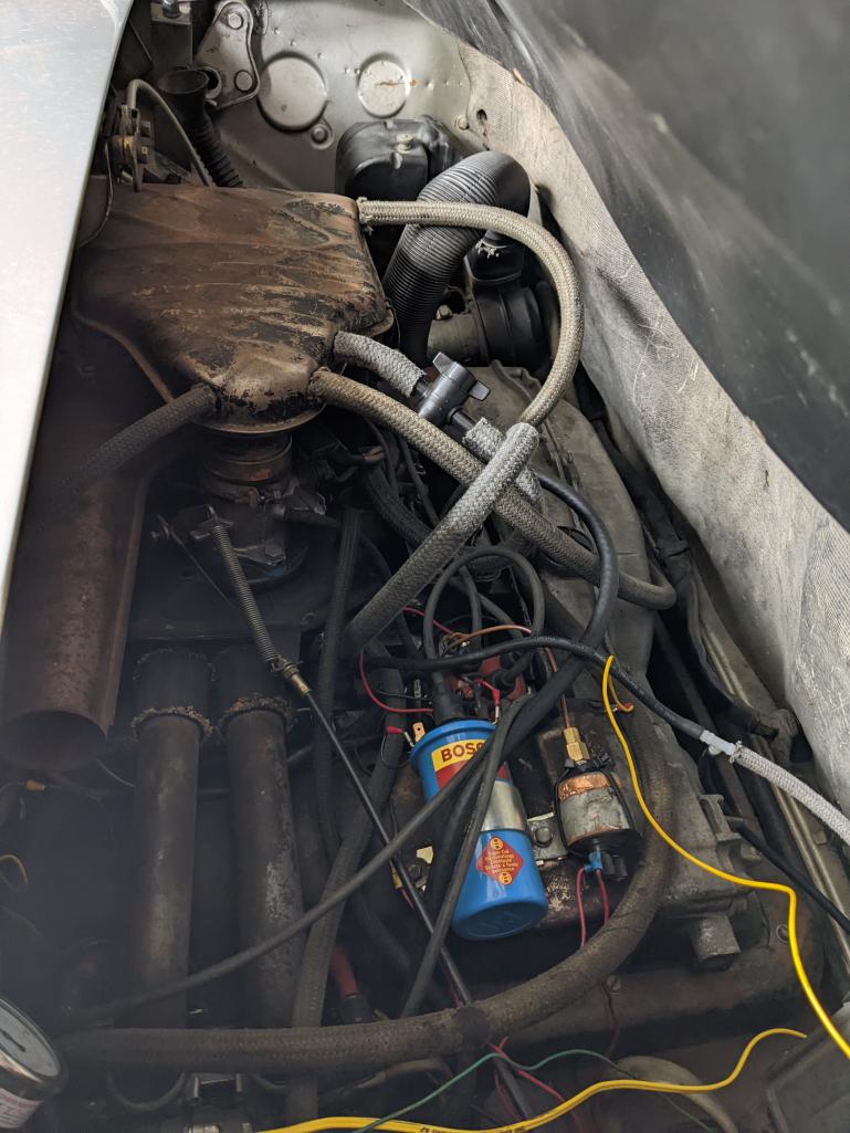 |
|
|
|
| pbanders |
May 21 2022, 07:17 AM
Post
#3
|
|
Senior Member Group: Members Posts: 939 Joined: 11-June 03 From: Phoenix, AZ Member No.: 805 |
QUOTE(emerygt350 @ May 21 2022, 04:14 AM)  Pbanders, have you run a vacuum gauge while driving? My numbers are quite a bit different and was curious about that. 17-18 at idle warm, dragging down a hill, 23ish is common. Decel works great, full open by 18.5.... My engine bay looks like a 50 year old car. Yours looks brand new. You can see my copper foil on the oil pressure sender, the extra ground to the shroud in yellow, and the cht sender wire being all ugly. Otherwise stock. And my aav bypass valve for troubleshooting. And the t for the in dash vacuum gauge I don't have a gauge, our numbers look reasonably similar to me. Will do a temporary gauge and check it out. Is your fuel evaporation system present? Looks like you have the fresh air supply for it plumbed to your flashback trap. Looks like a 73 throttle body, as you have the vacuum advance port. What's the yellow two conductor wire at the bottom of the pic for? Is that a fuel pressure gauge in the lower left corner? |
|
|
|
| emerygt350 |
May 21 2022, 09:33 PM
Post
#4
|
|
Advanced Member Group: Members Posts: 2,091 Joined: 20-July 21 From: Upstate, NY Member No.: 25,740 Region Association: North East States |
QUOTE(pbanders @ May 21 2022, 07:17 AM) QUOTE(emerygt350 @ May 21 2022, 04:14 AM) Pbanders, have you run a vacuum gauge while driving? My numbers are quite a bit different and was curious about that. 17-18 at idle warm, dragging down a hill, 23ish is common. Decel works great, full open by 18.5.... My engine bay looks like a 50 year old car. Yours looks brand new. You can see my copper foil on the oil pressure sender, the extra ground to the shroud in yellow, and the cht sender wire being all ugly. Otherwise stock. And my aav bypass valve for troubleshooting. And the t for the in dash vacuum gauge I don't have a gauge, our numbers look reasonably similar to me. Will do a temporary gauge and check it out. Is your fuel evaporation system present? Looks like you have the fresh air supply for it plumbed to your flashback trap. Looks like a 73 throttle body, as you have the vacuum advance port. What's the yellow two conductor wire at the bottom of the pic for? Is that a fuel pressure gauge in the lower left corner? It would be nice to know about the vac. I believe I have it all going correctly. Counter clockwise I have decel, EVAP, aav, then pcv (fresh air in to the flashback trap). Are the ports on the air cleaner different? The ugly yellow is for the cht gauge. And yes, fuel pressure gauge a very helpful addition. |
|
|
|
| pbanders |
May 22 2022, 07:18 AM
Post
#5
|
|
Senior Member Group: Members Posts: 939 Joined: 11-June 03 From: Phoenix, AZ Member No.: 805 |
QUOTE(emerygt350 @ May 21 2022, 08:33 PM) QUOTE(pbanders @ May 21 2022, 07:17 AM) QUOTE(emerygt350 @ May 21 2022, 04:14 AM) Pbanders, have you run a vacuum gauge while driving? My numbers are quite a bit different and was curious about that. 17-18 at idle warm, dragging down a hill, 23ish is common. Decel works great, full open by 18.5.... My engine bay looks like a 50 year old car. Yours looks brand new. You can see my copper foil on the oil pressure sender, the extra ground to the shroud in yellow, and the cht sender wire being all ugly. Otherwise stock. And my aav bypass valve for troubleshooting. And the t for the in dash vacuum gauge I don't have a gauge, our numbers look reasonably similar to me. Will do a temporary gauge and check it out. Is your fuel evaporation system present? Looks like you have the fresh air supply for it plumbed to your flashback trap. Looks like a 73 throttle body, as you have the vacuum advance port. What's the yellow two conductor wire at the bottom of the pic for? Is that a fuel pressure gauge in the lower left corner? It would be nice to know about the vac. I believe I have it all going correctly. Counter clockwise I have decel, EVAP, aav, then pcv (fresh air in to the flashback trap). Are the ports on the air cleaner different? The ugly yellow is for the cht gauge. And yes, fuel pressure gauge a very helpful addition. OK, I see what you're doing. You have it (CCW) Decel/Evap/AAR/Flashback. It's normally Decel/Flashback/AAR/Evap. Putting the Evap where you have it makes it cross in front of the engine fan, probably OK but not as Porsche did it. As you have your Decel in place, but it's not visible in the pic, which port are you running that hose from the airbox to? The port on the end, or the port on the side? You may not be aware of this, but most of the hose diagrams are wrong when it comes to the Decel valve connections. Vacuum should be connected to the 5 mm control port (the one with the thread and nut) and to the 9 mm port on the opposite end, and fresh air from the air box should be connected to the 9 mm port on the side. Most diagrams have the connections to the two 9 mm ports reversed. If you connect it that way, the valve cannot work, because there's vacuum on both sides of the internal diaphragm, and it never moves, no matter what the vacuum is in the intake plenum. |
|
|
|
| emerygt350 |
May 23 2022, 06:05 AM
Post
#6
|
|
Advanced Member Group: Members Posts: 2,091 Joined: 20-July 21 From: Upstate, NY Member No.: 25,740 Region Association: North East States |
QUOTE(pbanders @ May 22 2022, 07:18 AM) [] OK, I see what you're doing. You have it (CCW) Decel/Evap/AAR/Flashback. It's normally Decel/Flashback/AAR/Evap. Putting the Evap where you have it makes it cross in front of the engine fan, probably OK but not as Porsche did it. As you have your Decel in place, but it's not visible in the pic, which port are you running that hose from the airbox to? The port on the end, or the port on the side? You may not be aware of this, but most of the hose diagrams are wrong when it comes to the Decel valve connections. Vacuum should be connected to the 5 mm control port (the one with the thread and nut) and to the 9 mm port on the opposite end, and fresh air from the air box should be connected to the 9 mm port on the side. Most diagrams have the connections to the two 9 mm ports reversed. If you connect it that way, the valve cannot work, because there's vacuum on both sides of the internal diaphragm, and it never moves, no matter what the vacuum is in the intake plenum. Interesting! When I get back to the states I will double check that! It's been a while so I can't remember if I just followed the diagram or used common sense. Nice to know about the EVAP. I plumbed that based on the length of hose available. Figured there was a reason for all of that hose but I guess it could have been messed with. |
|
|
|
| emerygt350 |
May 23 2022, 06:19 AM
Post
#7
|
|
Advanced Member Group: Members Posts: 2,091 Joined: 20-July 21 From: Upstate, NY Member No.: 25,740 Region Association: North East States |
[quote name='emerygt350' date='May 23 2022, 06:05 AM' post='3003602']
[quote name='pbanders' post='3003407' date='May 22 2022, 07:18 AM'] []. Vacuum should be connected to the 5 mm control port (the one with the thread and nut) and to the 9 mm port on the opposite end, and fresh air from the air box should be connected to the 9 mm port on the side. Most diagrams have the connections to the two 9 mm ports reversed. If you connect it that way, the valve cannot work, because there's vacuum on both sides of the internal diaphragm, and it never moves, no matter what the vacuum is in the intake plenum. [/quote] Just to be clear. Vacuum goes to the small port facing the passenger, that is what I have for sure. And vacuum also to the posterior port facing the rear of the car? Wouldn't that create vacuum on both sides? I don't really know what the construction of the valve looks like internally but it just feels like it would... |
|
|
|
| pbanders |
May 23 2022, 07:18 AM
Post
#8
|
|
Senior Member Group: Members Posts: 939 Joined: 11-June 03 From: Phoenix, AZ Member No.: 805 |
[quote name='emerygt350' date='May 23 2022, 05:19 AM' post='3003604']
[quote name='emerygt350' date='May 23 2022, 06:05 AM' post='3003602'] [quote name='pbanders' post='3003407' date='May 22 2022, 07:18 AM'] []. Vacuum should be connected to the 5 mm control port (the one with the thread and nut) and to the 9 mm port on the opposite end, and fresh air from the air box should be connected to the 9 mm port on the side. Most diagrams have the connections to the two 9 mm ports reversed. If you connect it that way, the valve cannot work, because there's vacuum on both sides of the internal diaphragm, and it never moves, no matter what the vacuum is in the intake plenum. [/quote] Just to be clear. Vacuum goes to the small port facing the passenger, that is what I have for sure. And vacuum also to the posterior port facing the rear of the car? Wouldn't that create vacuum on both sides? I don't really know what the construction of the valve looks like internally but it just feels like it would... [/quote] Below is a diagram of the internals of the decel valve. As you can see, it's two chambers separated by a flexible diaphragm, and a valve covering the end port. If vacuum is applied to both the control and the side port, and the end port is connected to atmospheric pressure, the diaphragm has the same pressure on both sides and will never move, no matter what pressure is applied. This configuration is the way many of the hose diagrams show. Now, swap the hoses on the side and end port, so that the side port is connected to atmospheric pressure and the end port to vacuum. If P1 is at atmospheric pressure and P2 is at a vacuum below the setpoint, the tension spring will hold the valve shut. Once P2 is at a high enough vacuum to overcome the spring tension, the valve opens, and P1 now cannot exceed the setpoint vacuum, limiting the vacuum - which is why the device is also called a vacuum limiter. BTW, this is not conjecture, I have tested it in both configurations using my hand vacuum pump and hoses and tee connectors to apply vacuum to the ports. You can test it yourself, this is how it works. Attached image(s) 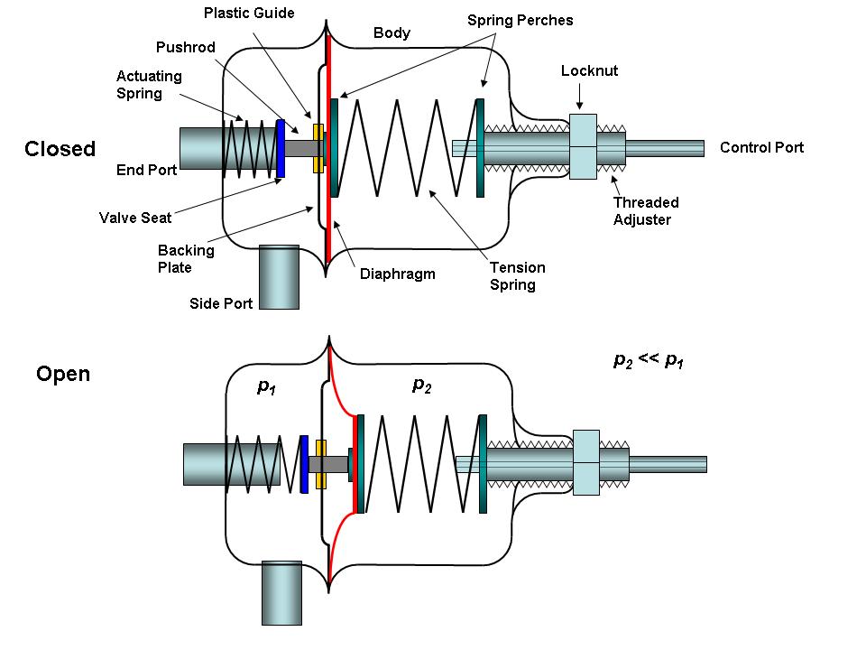
|
|
|
|
Posts in this topic
 pbanders Engine Bay Pics: Post Yours Here May 20 2022, 04:58 PM
 pbanders Passenger side, looking across.
* You can see I d... May 20 2022, 04:59 PM pbanders Passenger side, looking down
* Yes, those are the... May 20 2022, 05:01 PM
pbanders Passenger side, looking across.
* You can see I d... May 20 2022, 04:59 PM pbanders Passenger side, looking down
* Yes, those are the... May 20 2022, 05:01 PM
 ndfrigi [quote name='pbanders' post='3003100... May 21 2022, 07:07 AM pbanders Driver's side, looking across.
* Trickle char... May 20 2022, 05:01 PM pbanders Driver's side, looking down.
Only thing of no... May 20 2022, 05:03 PM Maltese Falcon I swear this is an original 1974 2L engine bay, sl... May 20 2022, 08:29 PM pbanders Fantastic, great pic May 20 2022, 10:15 PM 76-914 Ya beat me to it Marty. Original(ly) 1.7L. :D
May 20 2022, 10:30 PM SirAndy Somehow, this all fits without any cutting ...
:D... May 20 2022, 11:46 PM emerygt350 ]
Just switched the decel to the right configurat... May 26 2022, 08:13 AM wonkipop
[quote name='emerygt350' date='May 2... May 26 2022, 04:24 PM ClayPerrine :agree:
It all fits without cutting..... May 21 2022, 05:25 AM pbanders
:agree:
It all fits without cutting.....
C... May 21 2022, 07:33 AM ClayPerrine
:agree:
It all fits without cutting.....
... May 22 2022, 07:22 PM brant 2.0 May 21 2022, 07:01 AM pbanders
2.0
Super-clean, beautiful. May 21 2022, 07:32 AM Superhawk996
2.0
As an engineer I love all the FI and the mo... May 21 2022, 08:54 AM pbanders Wow, some impressive engine bays! May 21 2022, 07:11 AM KevinW Work in progress May 21 2022, 07:13 AM pbanders
Work in progress
Very impressive! May 21 2022, 07:30 AM pencap914
Work in progress
I might try this throttle link... May 26 2022, 03:26 PM tygaboy Like others have already mentioned: "original... May 21 2022, 08:03 AM pbanders
Like others have already mentioned: "origina... May 21 2022, 11:32 AM BillJ Mine May 21 2022, 09:03 AM pbanders
Mine
Beautiful. May 21 2022, 11:33 AM barefoot
Need a low profile breather can to drain to oil... May 21 2022, 01:05 PM pbanders
Need a low profile breather can to drain to oi... May 21 2022, 04:27 PM 914043 not as eye popping as the two previous 6s but stoc... May 21 2022, 04:38 PM Michael N 2.4 MFI S engine.
May 21 2022, 06:23 PM rgalla9146
2.4 MFI S engine.
OOOOH La LA !... May 29 2022, 07:48 AM bbrock Here's mine
May 21 2022, 06:51 PM VegasRacer 3.0 liter. :driving: :D A notch was nec... May 21 2022, 09:13 PM sb914 A different view! May 22 2022, 07:44 AM FlacaProductions I'll throw this in here - took it recently whi... May 22 2022, 09:11 AM JeffBowlsby Mixin it up with some stock goodness May 22 2022, 10:47 AM pbanders
Mixin it up with some stock goodness
Nice! May 22 2022, 10:24 PM JmuRiz Yowzer!!! May 22 2022, 08:56 PM rick 918-S Completely Stock :assimilate:
The Money Shot May 23 2022, 12:42 PM tygaboy Just another 3.6 swap. :evilgrin: May 23 2022, 12:44 PM NotLance
I’ve got a 2.0L with duel webers in a 1970.
... May 26 2022, 10:11 AM friethmiller
I’ve got a 2.0L with duel webers in a 1970.
L... May 27 2022, 08:40 AM Cairo94507 @tygaboy - Hey that fits remarkably well. :beer... May 26 2022, 03:44 PM friethmiller OK, here's my '74's engine bay. This ... May 26 2022, 04:57 PM pbanders
OK, here's my '74's engine bay. This... May 26 2022, 10:21 PM ClayPerrine
OK, here's my '74's engine bay. This... May 27 2022, 11:27 AM friethmiller
Where did you get the AC compressor mount? I am ... May 27 2022, 12:56 PM Cairo94507 That's very clean and a nice small compressor.... May 26 2022, 05:53 PM mlindner OK can I play. Mark May 27 2022, 01:48 PM friethmiller
OK can I play. Mark
Sweet! May 27 2022, 03:16 PM Retroracer Engine bay: New-ish addition - Sheridan rain hats
... May 27 2022, 03:35 PM bkrantz 2056 with dual ITBs, megasquirt, and electronic ig... May 27 2022, 08:51 PM mlindner And this is the best way to get to my engine bay. May 28 2022, 09:42 AM campbellcj http://www.914world.com/bbs2/uploads_offsite/live.... May 28 2022, 11:40 AM jims914 This is my 75 914 of 41 years. May 28 2022, 12:22 PM nein14 RE: Engine Bay Pics: Post Yours Here May 29 2022, 07:01 AM Cairo94507 @jims914 - Jim that looks very nice. I like that... May 29 2022, 07:08 AM 914werke 2056 L-Jet + some mods
May 29 2022, 11:34 AM emerygt350
I mean you didn't say it had to be a 914...... May 29 2022, 05:24 PM Lockwodo
I mean you didn't say it had to be a 914..... May 29 2022, 05:35 PM emerygt350
I mean you didn't say it had to be a 914.... May 30 2022, 04:12 AM wonkipop
I mean you didn't say it had to be a 914..... May 30 2022, 03:42 AM Freezin 914
2056 with dual ITBs, megasquirt, and electronic i... May 29 2022, 08:35 PM 914 Ranch Mine
It seems to be on going, more to come late... May 29 2022, 11:23 PM cali914 RE: Engine Bay Pics: Post Yours Here Jun 1 2022, 11:13 PM william1764 RE: Engine Bay Pics: Post Yours Here Jun 3 2022, 11:41 AM Freezin 914 My 74, (as purchased) Needs some work. Jun 13 2022, 06:47 PM
ndfrigi [quote name='pbanders' post='3003100... May 21 2022, 07:07 AM pbanders Driver's side, looking across.
* Trickle char... May 20 2022, 05:01 PM pbanders Driver's side, looking down.
Only thing of no... May 20 2022, 05:03 PM Maltese Falcon I swear this is an original 1974 2L engine bay, sl... May 20 2022, 08:29 PM pbanders Fantastic, great pic May 20 2022, 10:15 PM 76-914 Ya beat me to it Marty. Original(ly) 1.7L. :D
May 20 2022, 10:30 PM SirAndy Somehow, this all fits without any cutting ...
:D... May 20 2022, 11:46 PM emerygt350 ]
Just switched the decel to the right configurat... May 26 2022, 08:13 AM wonkipop
[quote name='emerygt350' date='May 2... May 26 2022, 04:24 PM ClayPerrine :agree:
It all fits without cutting..... May 21 2022, 05:25 AM pbanders
:agree:
It all fits without cutting.....
C... May 21 2022, 07:33 AM ClayPerrine
:agree:
It all fits without cutting.....
... May 22 2022, 07:22 PM brant 2.0 May 21 2022, 07:01 AM pbanders
2.0
Super-clean, beautiful. May 21 2022, 07:32 AM Superhawk996
2.0
As an engineer I love all the FI and the mo... May 21 2022, 08:54 AM pbanders Wow, some impressive engine bays! May 21 2022, 07:11 AM KevinW Work in progress May 21 2022, 07:13 AM pbanders
Work in progress
Very impressive! May 21 2022, 07:30 AM pencap914
Work in progress
I might try this throttle link... May 26 2022, 03:26 PM tygaboy Like others have already mentioned: "original... May 21 2022, 08:03 AM pbanders
Like others have already mentioned: "origina... May 21 2022, 11:32 AM BillJ Mine May 21 2022, 09:03 AM pbanders
Mine
Beautiful. May 21 2022, 11:33 AM barefoot
Need a low profile breather can to drain to oil... May 21 2022, 01:05 PM pbanders
Need a low profile breather can to drain to oi... May 21 2022, 04:27 PM 914043 not as eye popping as the two previous 6s but stoc... May 21 2022, 04:38 PM Michael N 2.4 MFI S engine.
May 21 2022, 06:23 PM rgalla9146
2.4 MFI S engine.
OOOOH La LA !... May 29 2022, 07:48 AM bbrock Here's mine
May 21 2022, 06:51 PM VegasRacer 3.0 liter. :driving: :D A notch was nec... May 21 2022, 09:13 PM sb914 A different view! May 22 2022, 07:44 AM FlacaProductions I'll throw this in here - took it recently whi... May 22 2022, 09:11 AM JeffBowlsby Mixin it up with some stock goodness May 22 2022, 10:47 AM pbanders
Mixin it up with some stock goodness
Nice! May 22 2022, 10:24 PM JmuRiz Yowzer!!! May 22 2022, 08:56 PM rick 918-S Completely Stock :assimilate:
The Money Shot May 23 2022, 12:42 PM tygaboy Just another 3.6 swap. :evilgrin: May 23 2022, 12:44 PM NotLance
I’ve got a 2.0L with duel webers in a 1970.
... May 26 2022, 10:11 AM friethmiller
I’ve got a 2.0L with duel webers in a 1970.
L... May 27 2022, 08:40 AM Cairo94507 @tygaboy - Hey that fits remarkably well. :beer... May 26 2022, 03:44 PM friethmiller OK, here's my '74's engine bay. This ... May 26 2022, 04:57 PM pbanders
OK, here's my '74's engine bay. This... May 26 2022, 10:21 PM ClayPerrine
OK, here's my '74's engine bay. This... May 27 2022, 11:27 AM friethmiller
Where did you get the AC compressor mount? I am ... May 27 2022, 12:56 PM Cairo94507 That's very clean and a nice small compressor.... May 26 2022, 05:53 PM mlindner OK can I play. Mark May 27 2022, 01:48 PM friethmiller
OK can I play. Mark
Sweet! May 27 2022, 03:16 PM Retroracer Engine bay: New-ish addition - Sheridan rain hats
... May 27 2022, 03:35 PM bkrantz 2056 with dual ITBs, megasquirt, and electronic ig... May 27 2022, 08:51 PM mlindner And this is the best way to get to my engine bay. May 28 2022, 09:42 AM campbellcj http://www.914world.com/bbs2/uploads_offsite/live.... May 28 2022, 11:40 AM jims914 This is my 75 914 of 41 years. May 28 2022, 12:22 PM nein14 RE: Engine Bay Pics: Post Yours Here May 29 2022, 07:01 AM Cairo94507 @jims914 - Jim that looks very nice. I like that... May 29 2022, 07:08 AM 914werke 2056 L-Jet + some mods
May 29 2022, 11:34 AM emerygt350
I mean you didn't say it had to be a 914...... May 29 2022, 05:24 PM Lockwodo
I mean you didn't say it had to be a 914..... May 29 2022, 05:35 PM emerygt350
I mean you didn't say it had to be a 914.... May 30 2022, 04:12 AM wonkipop
I mean you didn't say it had to be a 914..... May 30 2022, 03:42 AM Freezin 914
2056 with dual ITBs, megasquirt, and electronic i... May 29 2022, 08:35 PM 914 Ranch Mine
It seems to be on going, more to come late... May 29 2022, 11:23 PM cali914 RE: Engine Bay Pics: Post Yours Here Jun 1 2022, 11:13 PM william1764 RE: Engine Bay Pics: Post Yours Here Jun 3 2022, 11:41 AM Freezin 914 My 74, (as purchased) Needs some work. Jun 13 2022, 06:47 PM |
2 User(s) are reading this topic (2 Guests and 0 Anonymous Users)
0 Members:

|
Lo-Fi Version | Time is now: 14th May 2024 - 02:46 AM |
Invision Power Board
v9.1.4 © 2024 IPS, Inc.