|
|
|
Porsche, and the Porsche crest are registered trademarks of Dr. Ing. h.c. F. Porsche AG.
This site is not affiliated with Porsche in any way. Its only purpose is to provide an online forum for car enthusiasts. All other trademarks are property of their respective owners. |
|
|

  |

| cooler |
 Dec 2 2022, 06:28 PM Dec 2 2022, 06:28 PM
Post
#1
|
|
"Very Interesting!"  Group: Members Posts: 32 Joined: 6-December 11 From: British Columbia Member No.: 13,865 Region Association: Canada |
hello 914 structural experts,
I am planning to create a new crossmember to stiffen rear suspension and support engine. The 914 rear suspension console is well known to flex under racing stress and was reinforced by factory racing teams. I intend to address the flexing issue and create engine (Audi V8) mounting locations with a new crossmember and diagonal tension members. The attached photo shows the location of crossmember (red) and diagonal tension members (blue). The crossmember spans between the suspension consoles, on center with the trailing arm pivot axis. The diagonal tension members span also from rear suspension consoles to firewall, near center tunnel. This assembly will need to be removable to facilitate engine removal and is intended to stiffen the entire engine bay/rear suspension. I am struggling with detailing the crossmember bolted connections at suspension consoles. I assume each connections should include two bolts each but, should the bolts be loaded in shear or in tension? What size should the bolts be? Thanks in advance 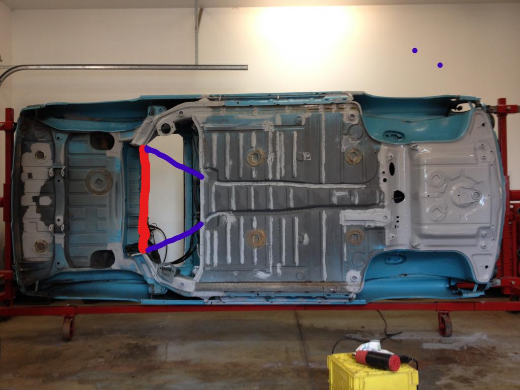 |
   |

 
|
| Charles Freeborn |
Dec 3 2022, 09:39 AM
Post
#2
|
|
Member Group: Members Posts: 282 Joined: 21-May 14 From: United States Member No.: 17,377 Region Association: Pacific Northwest |
QUOTE(cooler @ Dec 2 2022, 04:28 PM)  hello 914 structural experts, I am planning to create a new crossmember to stiffen rear suspension and support engine. The 914 rear suspension console is well known to flex under racing stress and was reinforced by factory racing teams. I intend to address the flexing issue and create engine (Audi V8) mounting locations with a new crossmember and diagonal tension members. The attached photo shows the location of crossmember (red) and diagonal tension members (blue). The crossmember spans between the suspension consoles, on center with the trailing arm pivot axis. The diagonal tension members span also from rear suspension consoles to firewall, near center tunnel. This assembly will need to be removable to facilitate engine removal and is intended to stiffen the entire engine bay/rear suspension. I am struggling with detailing the crossmember bolted connections at suspension consoles. I assume each connections should include two bolts each but, should the bolts be loaded in shear or in tension? What size should the bolts be? Thanks in advance Wow. An Audi V8 in a 914 sounds like a barrel of fun! AS for your crossmember questions I'd say make the flanges on the ends of the tubing somewhere in the 3/16" thick range (3mm?) and try to use 4 bolts per flange. Weld the flanges to the chassis with weld nuts pre-attached. I'd use a minimum of 4/8mm bolts per, 10.9 hardness minimum. As for the shear / tension question, the fastener choice (hardness) is the mitigating factor. |
|
|
|
| stownsen914 |
Dec 3 2022, 11:55 AM
Post
#3
|
|
Senior Member Group: Members Posts: 946 Joined: 3-October 06 From: Ossining, NY Member No.: 6,985 Region Association: None |
You're correct to reinforce this area of the car, it can use it. As for whether to orient the bolts in tension vs. shear, it's an interesting question. If it were me, I'd do whichever is more convenient from a fabrication standpoint. A tension fastening arrangement might be easier at the firewall end (if I'm envisioning it correctly), and in shear at the suspension console end. I've seen supports made for this purpose, using rod ends. I imagine it's helpful to give any support you can in this area, but I'd prefer a solid attachment to counteract twisting forces. With the rod end arrangement, you get resistance to tension and compression forces but no resistance to twisting.
|
|
|
|
| Brett W |
Dec 3 2022, 06:09 PM
Post
#4
|
|
Advanced Member Group: Members Posts: 2,859 Joined: 17-September 03 From: huntsville, al Member No.: 1,169 Region Association: None |
Think of or go look through a junkyard and see how the OEs attach crossmembers and what they use for shapes. In your case, you are not using the crossmember to carry suspension loads or crash protection, so yours can be something relatively simple.
I would use 12-14mm bolts the cross bar can remain single shear up into the body (assuming you want to keep the factory orientation). Weld some 16ga reinforcements around the tunnel area. Then build some double shear saddle brackets for a each leg on the corner of the firewall. That will keep the whole structure up above or level with the floor pan to keep it away from road damage. If you want to go whole hog, I would build a shear plate out of aluminum plate. It could double as engine mount and let it tie into a minimum 4 points along the base of the firewall and then on the lower longitudinal and suspension console. The problem will be how low the pan hangs in relation to this plate/firewall/suspension console. |
|
|
|
| cooler |
Dec 4 2022, 04:06 PM
Post
#5
|
|
"Very Interesting!" Group: Members Posts: 32 Joined: 6-December 11 From: British Columbia Member No.: 13,865 Region Association: Canada |
Hello Again,
Thank you all for taking the time to respond. I have studied cars with removable subframes/crossmembers. The intent of how the loads are transferred are not always clear, sometimes rubber isolating mounting points are used. My intent is to stiffen the chassis, to maximize stress transfer no rubber insulators will be used at chassis connections. The engine however will be mounted to crossmember via rubber mounts. I'm also thinking the load created by the engine are minimal when compared to loads transferred from the suspension. The engine loads are proportional to engine mass. The suspension loads are proportional to total mass of car. The members must be removable vertically to facilitate engine removal. I believe if the fasters were also aligned vertically, hole alignment and reassembly would be easier. I also believe that would load the fasteners more significantly in shear if vertical load from the engine are considered negligible. Shear loads on the bolts could be reduced or eliminated by dowel pins in the connection. I have seen old school hot rod crossmember connections made with flanged connections but, they are likely not typically removable. It would be a PITA to align those bolt holes on reassembly. I may have answered my own question but, I have one more! What, from a seat of pants perspective, to make you feel comfortable, should the crossmember be constructed of. Thanks again |
|
|
|
| infraredcalvin |
Dec 6 2022, 03:36 PM
Post
#6
|
|
Distracted Member Group: Members Posts: 1,628 Joined: 25-August 08 From: Ladera Ranch, CA Member No.: 9,463 Region Association: Southern California |
I'd recommend taking a look at the GT/Ferrari build in the garage, the cradle building process looks like it might be similar to yours...
|
 |
|
| cooler |
Dec 6 2022, 05:35 PM
Post
#7
|
|
"Very Interesting!" Group: Members Posts: 32 Joined: 6-December 11 From: British Columbia Member No.: 13,865 Region Association: Canada |
Yes, thanks for that.
Fortunately the Audi V8 mounts are concentric to the cross member and line up nicely with the suspension console. No engine cradle head aches! |
|
|
|
| Brett W |
Dec 7 2022, 09:32 AM
Post
#8
|
|
Advanced Member Group: Members Posts: 2,859 Joined: 17-September 03 From: huntsville, al Member No.: 1,169 Region Association: None |
Use the engine as a semi stressed member.
|
|
|
|
| cooler |
Dec 8 2022, 09:56 AM
Post
#9
|
|
"Very Interesting!" Group: Members Posts: 32 Joined: 6-December 11 From: British Columbia Member No.: 13,865 Region Association: Canada |
Semi-stressed member. What would that look like?
|
|
|
|
| Charles Freeborn |
Dec 8 2022, 10:09 AM
Post
#10
|
|
Member Group: Members Posts: 282 Joined: 21-May 14 From: United States Member No.: 17,377 Region Association: Pacific Northwest |
QUOTE(cooler @ Dec 8 2022, 07:56 AM) Semi-stressed member. What would that look like? My guess is you attach the engine to either side of the chassis and the engine becomes a structural member. Brett will no doubt clarify. To answer your previous question, I'd use steel for the various members. Either .095 or .120 wall. Easy to source work and weld. Equally as important as the tube strength is the mounting plates. They need to fan out and catch as much of the monocoque structure as possible. Otherwise you're attaching a girder to a soda can.. |
|
|
|
| cooler |
Dec 9 2022, 11:41 AM
Post
#11
|
|
"Very Interesting!" Group: Members Posts: 32 Joined: 6-December 11 From: British Columbia Member No.: 13,865 Region Association: Canada |
Thanks for your input,
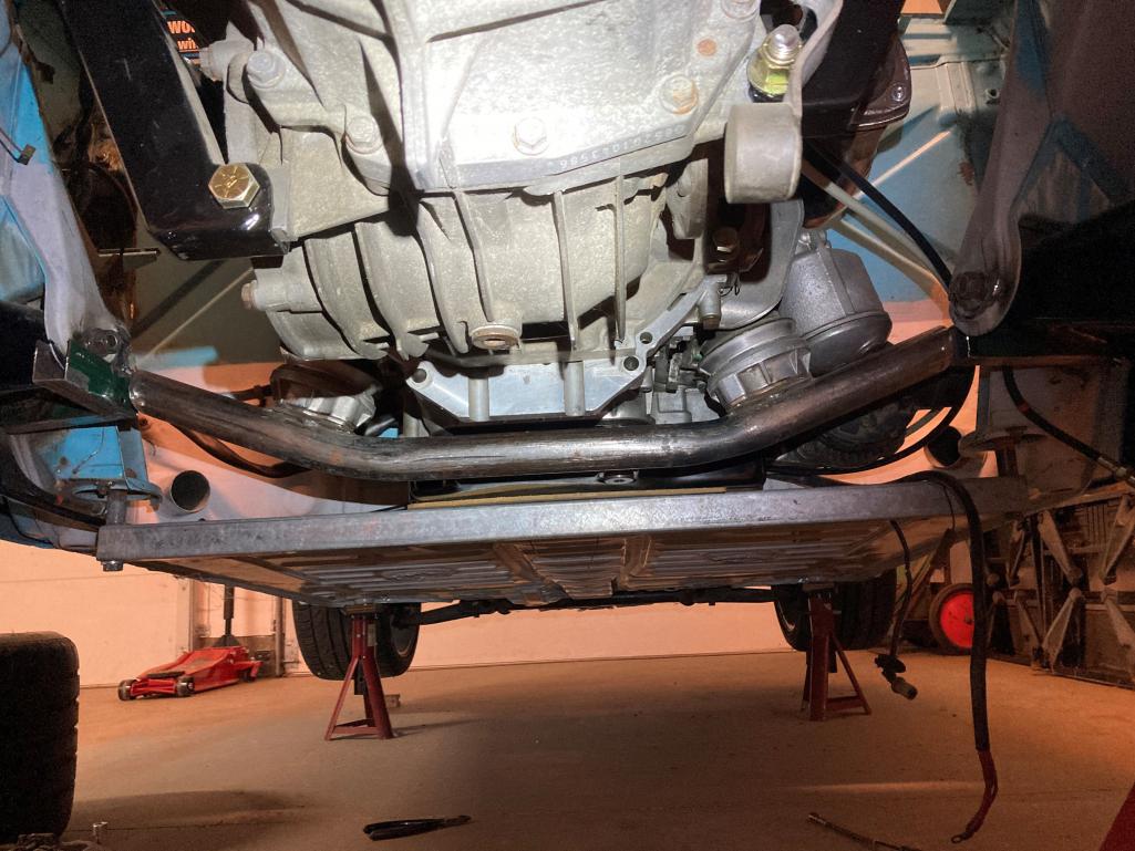
Stressing the engine as a structural member raises a couple concerns. 1. Will the engine withstand these forces and fatigue? Will the engine vibration transfer into the chassis, fatigue chassis components and occupants? The term semi-stress is not clear. Does this means some kind of structural insulators incorporated? If so will the insulators effectively transfer stress and resist deflection? My objective is to support the engine and stiffen the rear suspension consoles. I have started fabrication of a crossmember using 1 3/4" .125 tube (pic below) but it looks kind of wimpy, especially with the drop in it. I want it to be stiff not just strong. So I'm thinking upgrading to 2x3 .120 tube. The diagonal tension members are also shown in pic, 3/4" swaged tubes from Speedway Motors with 1/2" rod ends. Let me know what you think Thanks 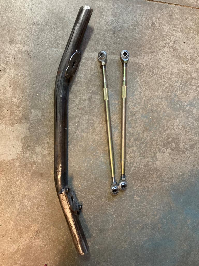 |
|
|
|
| Brett W |
Dec 9 2022, 09:07 PM
Post
#12
|
|
Advanced Member Group: Members Posts: 2,859 Joined: 17-September 03 From: huntsville, al Member No.: 1,169 Region Association: None |
Where are the engine mounts in relation to the rear suspension inner mounting ear?
Yeah if you have a standard production engine a fully stressed mount will definitely cause some negative distortion in the block. That won't end well. However if you could use the oil pan, bellhousing adapter, front motor plate, etc to pass those loads through instead of straight through the block, you could use that components you have to carry for double duty. One thing, that kinda matters, the rear inner pickup points only move in certain directions based on the loads from the tire. It really twists in plane and in a vertical plane. Your "dinky brace" to the tunnel will help the in plane twist. The Vertical you won't control with a simple crossmember. That needs to go to a cage which ties to the front of the chassis. On normal street use there just isn't that much lateral bending of that console. So you adding a "straight" crossmember across the engine bad doesn't really gain you much. Adding a flat shear plate across the whole underside of the engine bay, from firewall to suspension console and then use the engine mounts to stabilize the plate could be useful, but that may require you having a much shorter oil pan or machining the plate to allow the pan to sit below. Another option. Machine the plate and oil pan into one piece. Basically the plate becomes wings under on the pan and ties all of it together across the engine bay. OK I am getting a little outside of the realm of what normal people can fabricate. Yes any of the aforementioned mounting methods will contribute to vibration being transmitted through the chassis. |
|
|
|
| stownsen914 |
Dec 10 2022, 09:18 AM
Post
#13
|
|
Senior Member Group: Members Posts: 946 Joined: 3-October 06 From: Ossining, NY Member No.: 6,985 Region Association: None |
Personally not a big fan of solid mounted engines. Ever drive a car with one? Think tuning fork.
If you use that cross bar, see if you can triangulate it. When I first built my /6 racecar I built the crossbar out of 1 1/4" .095 and of course it flexed. Same material triangulated, 20+ years later, still going strong. |
|
|
|
| stownsen914 |
Dec 10 2022, 09:18 AM
Post
#14
|
|
Senior Member Group: Members Posts: 946 Joined: 3-October 06 From: Ossining, NY Member No.: 6,985 Region Association: None |
Dup
|
|
|
|
| PatMc |
Dec 10 2022, 03:24 PM
Post
#15
|
|
Member Group: Members Posts: 121 Joined: 27-June 21 From: Long Beach Member No.: 25,669 Region Association: None |
Not a vehicle structural expert...but I know a thing or 2 about fasteners. Bolts are never (or should never be) in shear.
Regardless as to how you design the joint, if the fastener is sized and torqued correctly for the loads at hand, and your joint has sufficient purchase, the clamped joint should deal with all the loads and the bolts won't know whether it's under load or not. If the bolts in a joint were subjected to cyclic loads, they would all experience fatigue failures, and they don't....most of the time. Bolts that are in applications where they act more like pins can and do wear. Bolts used in applications where the are used as bolts should not experience any wear or cyclic loads whatsoever. |
|
|
|
| cooler |
Dec 10 2022, 06:45 PM
Post
#16
|
|
"Very Interesting!" Group: Members Posts: 32 Joined: 6-December 11 From: British Columbia Member No.: 13,865 Region Association: Canada |
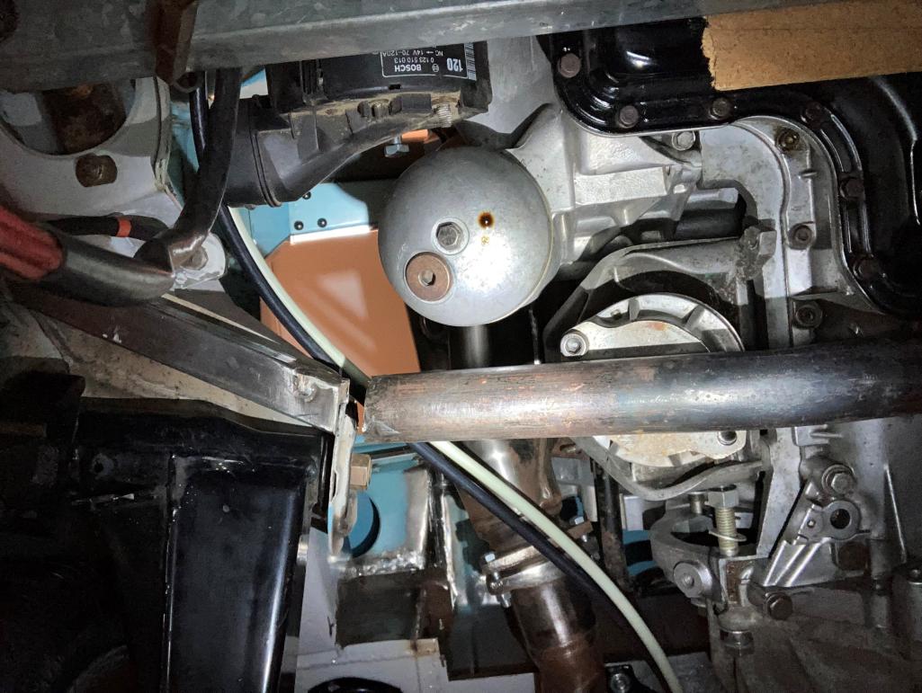
My apologies, these pics should have been posted. This shows the crossmember I have fabricated so far. Does it make my ass look big? I'm still trying to envision the connection detail between the crossmember and the suspension console. I just want it to look "factory", be solid and easy to assemble/dissemble.
 Attached thumbnail(s) 
|
|
|
|
| cooler |
Dec 10 2022, 06:47 PM
Post
#17
|
|
"Very Interesting!" Group: Members Posts: 32 Joined: 6-December 11 From: British Columbia Member No.: 13,865 Region Association: Canada |
 |
|
|
|
| Charles Freeborn |
Dec 11 2022, 11:19 AM
Post
#18
|
|
Member Group: Members Posts: 282 Joined: 21-May 14 From: United States Member No.: 17,377 Region Association: Pacific Northwest |
QUOTE(cooler @ Dec 10 2022, 04:47 PM) Wow. Cool project. Nothing more to add comment wise (you've gone well outside my realm of expertise), but following along with interest. Probably not going to be much help, but I'll try to get some pics of how my cage ties to all the various structural points. |
|
|
|
| cooler |
Dec 11 2022, 07:15 PM
Post
#19
|
|
"Very Interesting!" Group: Members Posts: 32 Joined: 6-December 11 From: British Columbia Member No.: 13,865 Region Association: Canada |
Thank you, I know I'm in over my head but, I'm having fun!
|
|
|
|
| stownsen914 |
Jan 10 2023, 05:35 PM
Post
#20
|
|
Senior Member Group: Members Posts: 946 Joined: 3-October 06 From: Ossining, NY Member No.: 6,985 Region Association: None |
@cooler I saw you PM'd me, not sure if you got my response. Check your PMs.
|
|
|
|
|
1 User(s) are reading this topic (1 Guests and 0 Anonymous Users)
0 Members:

|
Lo-Fi Version | Time is now: 10th May 2025 - 11:39 PM |
Invision Power Board
v9.1.4 © 2025 IPS, Inc.