|
|
|
Porsche, and the Porsche crest are registered trademarks of Dr. Ing. h.c. F. Porsche AG.
This site is not affiliated with Porsche in any way. Its only purpose is to provide an online forum for car enthusiasts. All other trademarks are property of their respective owners. |
|
|


| thesey914 |
 Aug 14 2005, 04:01 PM Aug 14 2005, 04:01 PM
Post
#1
|
|
Senior Member  Group: Benefactors Posts: 1,155 Joined: 1-January 03 From: Staffordshire -England Member No.: 66 |
Anyone know if voltage is applied across which pins makes the motor spin??
Attached image(s) 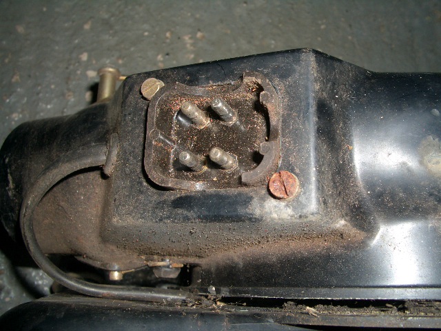
|
   |

 
|
  |
Replies(1 - 3)
| thesey914 |
Aug 14 2005, 04:01 PM
Post
#2
|
|
Senior Member Group: Benefactors Posts: 1,155 Joined: 1-January 03 From: Staffordshire -England Member No.: 66 |
'nother pic
Attached image(s) 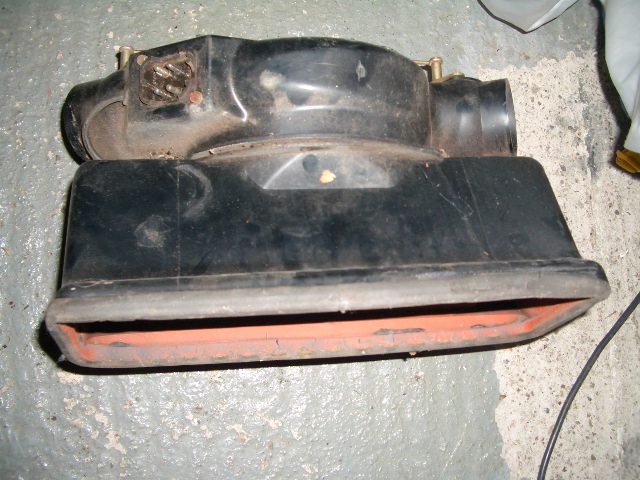
|
|
|
|
| Dr. Roger |
Aug 14 2005, 04:48 PM
Post
#3
|
|
A bat out of hell. Group: Members Posts: 3,944 Joined: 31-January 05 From: Hercules, California Member No.: 3,533 Region Association: Northern California |
i don't know but if i had to guess.... fan speed has low, med and high. if i remember correctly.
one pin would be ground. test by using ohm meter. touch one lead to steel casing and test for no resistance on the 4 pins. after finding the ground, that is your neg pin. attach neg power lead to that pin and listen for fan speed when applying positive energy to the other three pins. =-) if something begins to cook, please read someone elses disclaimer so that i may be disclaimed also. best of luck. |
|
|
|
| mihai914 |
Aug 14 2005, 06:24 PM
Post
#4
|
|
Senior Member Group: Members Posts: 800 Joined: 2-March 05 From: Montreal, QC Member No.: 3,697 Region Association: None |
From what I understand in the electrical diagrams, there is only one pin that is supplied with 12 volts, the one with the red and white wire going to it. The other three white wires are simple ground wires of which two go through resistors to reduce speed.
So I guess you connect the + to the red wire pin and - to any other one. Another option is to detaching the lower assembly from the housing by removing the two 8mm bolts and connect power directly to the motor leads which will be obvious. |
|
|
|
|
1 User(s) are reading this topic (1 Guests and 0 Anonymous Users)
0 Members:

|
Lo-Fi Version | Time is now: 26th May 2024 - 06:08 PM |
Invision Power Board
v9.1.4 © 2024 IPS, Inc.