|
|
|
Porsche, and the Porsche crest are registered trademarks of Dr. Ing. h.c. F. Porsche AG.
This site is not affiliated with Porsche in any way. Its only purpose is to provide an online forum for car enthusiasts. All other trademarks are property of their respective owners. |
|
|

  |

| Lilchopshop |
 Mar 9 2024, 07:54 AM Mar 9 2024, 07:54 AM
Post
#21
|
|
Member  Group: Members Posts: 111 Joined: 17-February 20 From: New York Member No.: 23,932 Region Association: North East States |
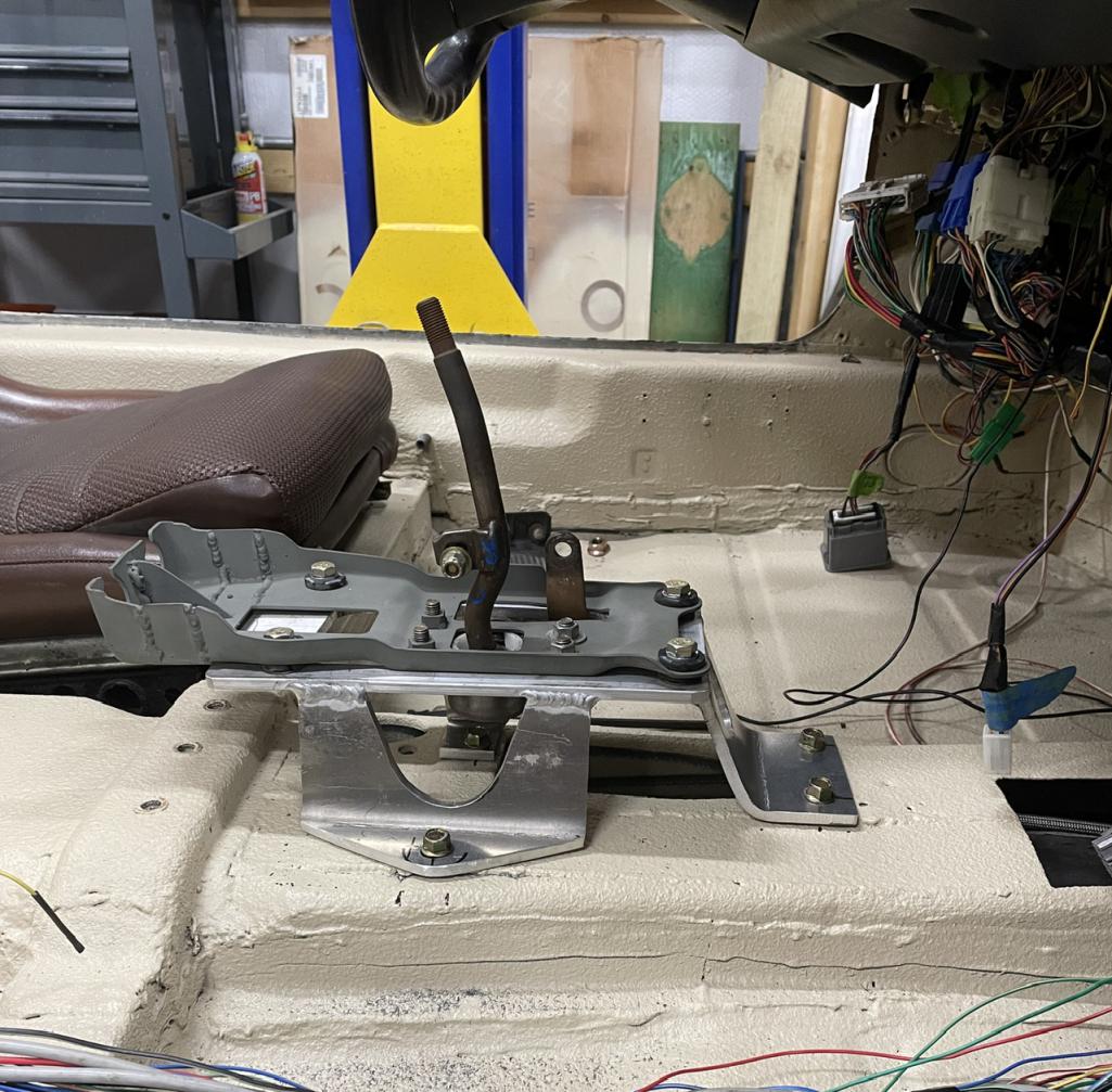
It’s been a while since my last post, but I’ve been chipping away at stuff. Here are some updates.
Shifter is mounted 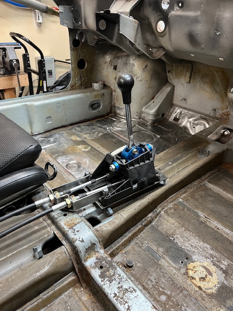 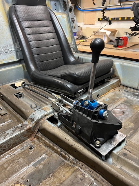 Cleaned up the driver’s footwell and welded all the access holes in the floor pan. 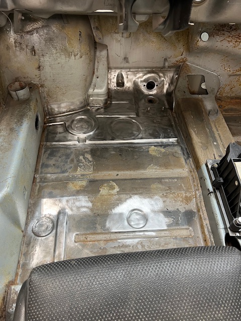 Finished the metal work on the rear valence (for now). I’m undecided if I’m going to keep this valence as is or make something else. I’m going to wait to see how I feel about it once the car is on wheels. 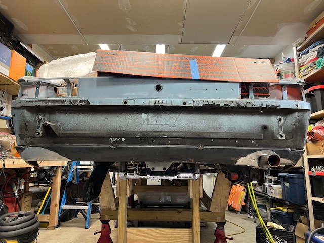 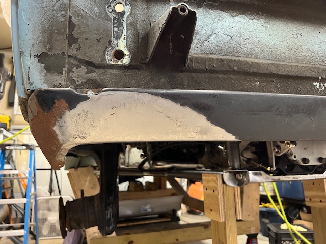 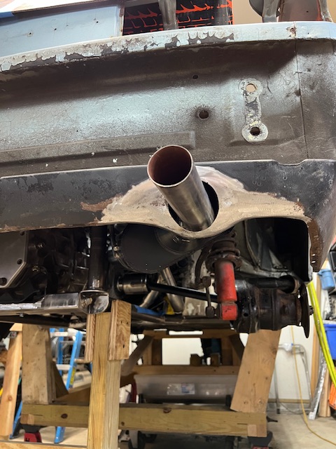 Did a rough install of the hybrid axles with the new exhaust and all the rear suspension parts to check for installation issues and adequate clearances. I also wanted all these parts in place for when I’m figuring out the shift cable routing. This was a good motivator for me. 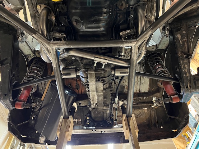 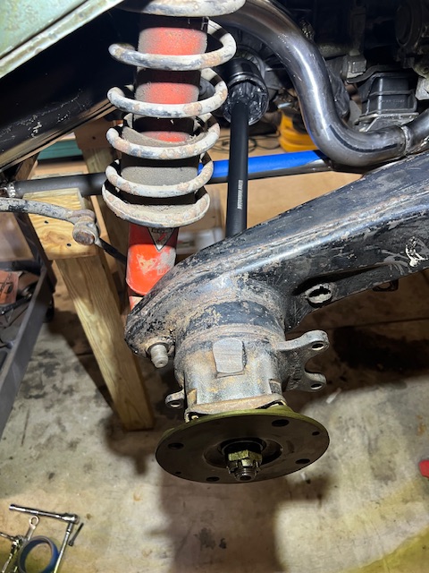 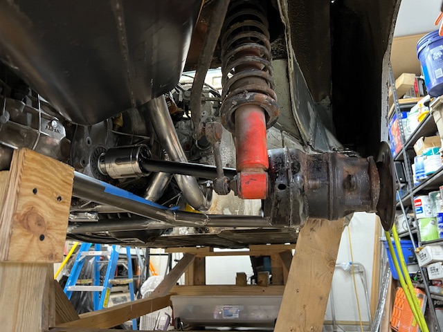 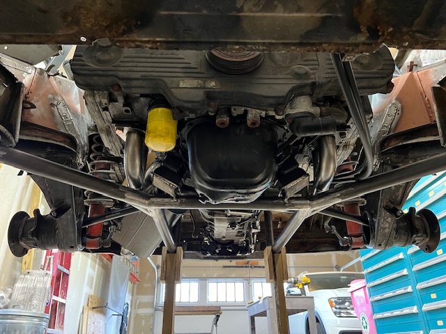 Next up is brackets for shift cables, and then start working out the pedal box mods for the hydraulic clutch. |
   |

 
|
| 76-914 |
Mar 9 2024, 08:08 AM
Post
#22
|
|
Repeat Offender & Resident Subaru Antagonist Group: Members Posts: 13,884 Joined: 23-January 09 From: Temecula, CA Member No.: 9,964 Region Association: Southern California |
It's good that you're back on it. Should be a nice reliable 914 when you're finished. (IMG:style_emoticons/default/beerchug.gif)
|
|
|
|
| Lilchopshop |
Mar 13 2025, 04:48 PM
Post
#23
|
|
Member Group: Members Posts: 111 Joined: 17-February 20 From: New York Member No.: 23,932 Region Association: North East States |
Well, a year went by since my last post… good thing I don’t have a deadline for this build! Over the last couple of months, I have been able to spend some more time on the car. Here are some progress pictures.
To get back into things and to test out my new welder, I thought I’d try making a shortened oil pan. I know these can be bought, but I wanted the exercise and I knew a homemade version would be cheaper. Started by cutting up a spare to see how things looked. 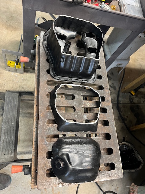 First I thought I’d try to keep the original bottom section with the drain plug, but it seemed like it was going to be too hard to join the parts back together and get it to look good like this. 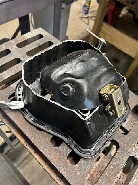 So I decided I would make a new, flatter bottom and I cut up the brand new pan I bought from Amazon. I made my own transition section to retain some of the volume. I also shortened the pick-up tube. 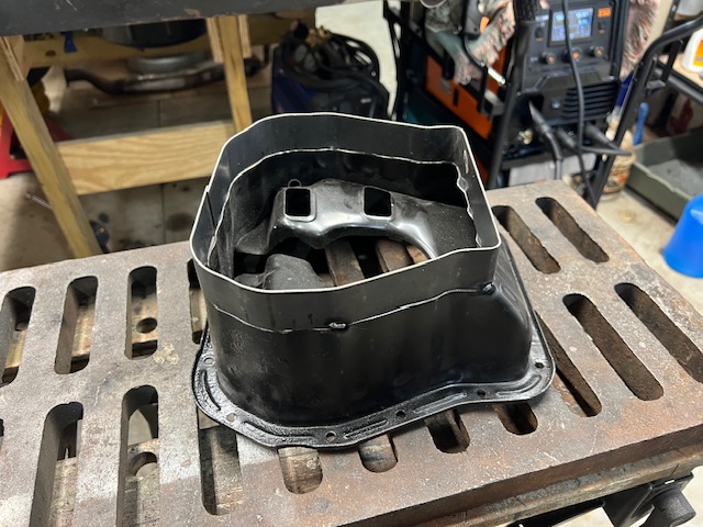 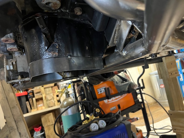 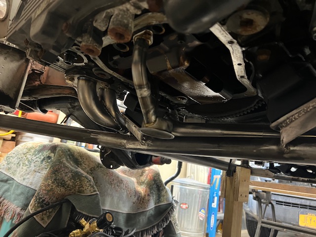 Then, after a lot of forming, welding, grinding, checking for leaks, re-welding and more grinding, I ended up with this. I bought a low profile drain plug because the stock plug stuck down farther than I wanted. I measured the volume of the finished product and it’s about 1/2 quart less than the stock pan. That doesn’t seem like a huge problem to me, but I’m willing to listen to opinions from others. 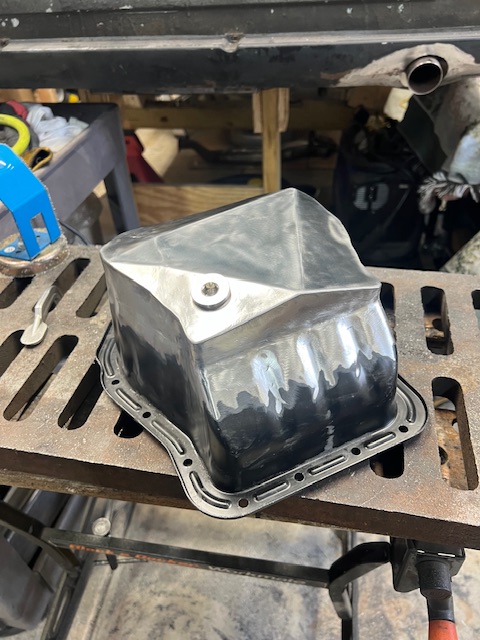 |
|
|
|
| Lilchopshop |
Mar 13 2025, 05:40 PM
Post
#24
|
|
Member Group: Members Posts: 111 Joined: 17-February 20 From: New York Member No.: 23,932 Region Association: North East States |
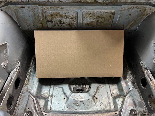
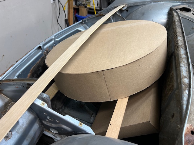
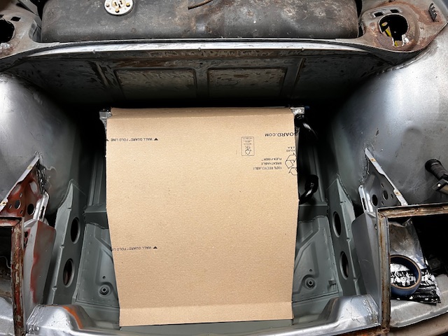
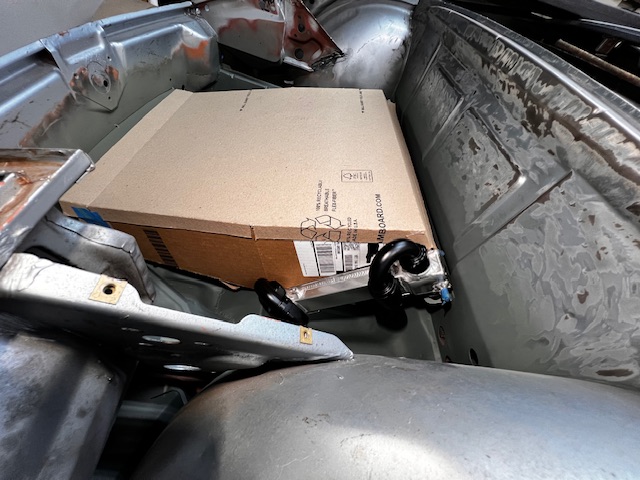
Next up, I thought I’d start figuring out radiator mounting. Originally, I was going to use a Mishimoto radiator and fans for a Celica like others have done, but I really wanted to be able to keep a spare tire in the frunk and I don’t like the idea of the collapsible spares. So, I bought a smaller, Scirocco-style radiator from Amazon. There are lots of variants to choose from and I ended up going with one that had mounting points for fans on both sides of the radiator. Before I started cutting big holes in the frunk, I made some cardboard mockups of the spare tire and the radiator to see what this might look like.
  Satisfied that there was a way to make this all work, I went all in and cut some holes. 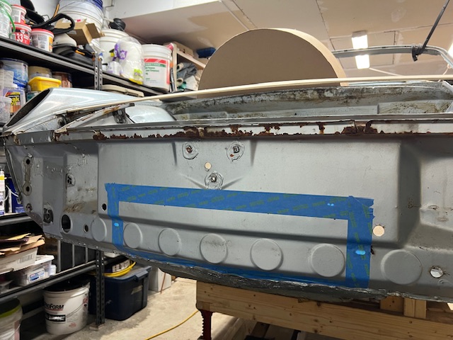 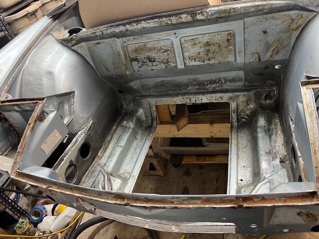 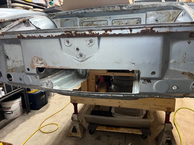 My plan is to run both cooling hoses up the drivers side longitudinal. This portion of the chassis is still wide open from the rust repair I have yet to button up. With this plan, I wanted to keep the radiator inlet/outlet on the drivers side. But with the radiator configurations I could find, it was going to be tricky to route the hoses this way without a lot of clunky hose bends and fittings. So, I cut the hose fittings off of the radiator and had a welder buddy of mine weld some AN16 bungs in place. This gives me lots of options for AN elbow fittings, etc. 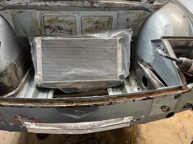 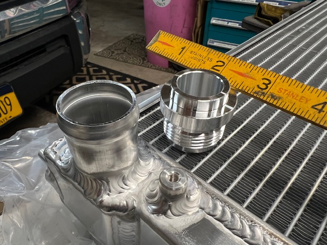 While working in the frunk, I realized that there was some mediocre repair to fix some front end collision damage sometime in the past. The chassis supports near the headlight buckets were not straightened very well and were poorly re-attached to the front cross piece. Also there was a lot of Zeibart coating under the headlight buckets that was bugging me, so I decided to pull out the chassis supports, straighten them and clean under the headlight buckets. 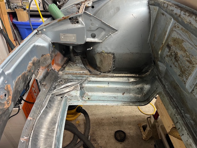 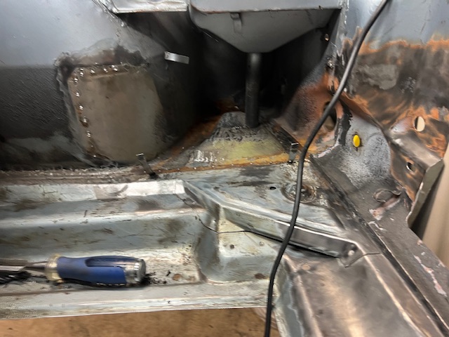 I ordered some Spal fans, some AN hose fittings and I made some parts to mount the radiator and mount the fans. 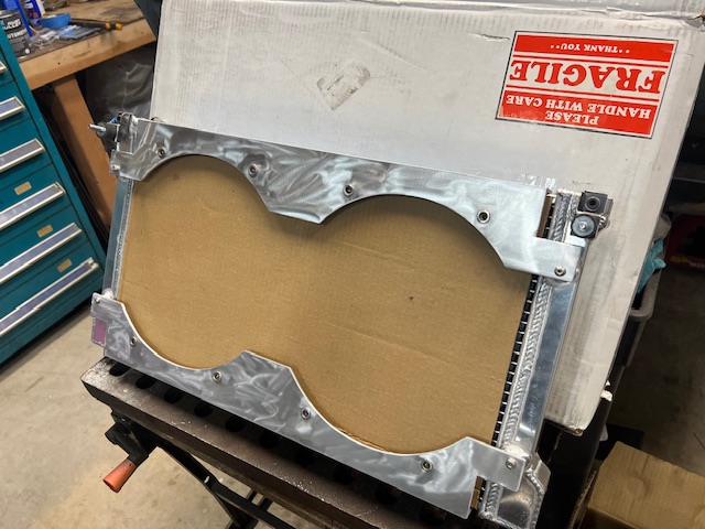 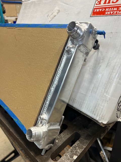 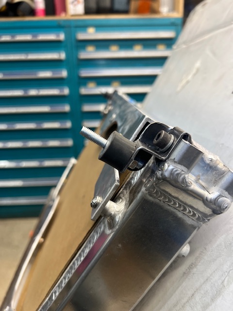 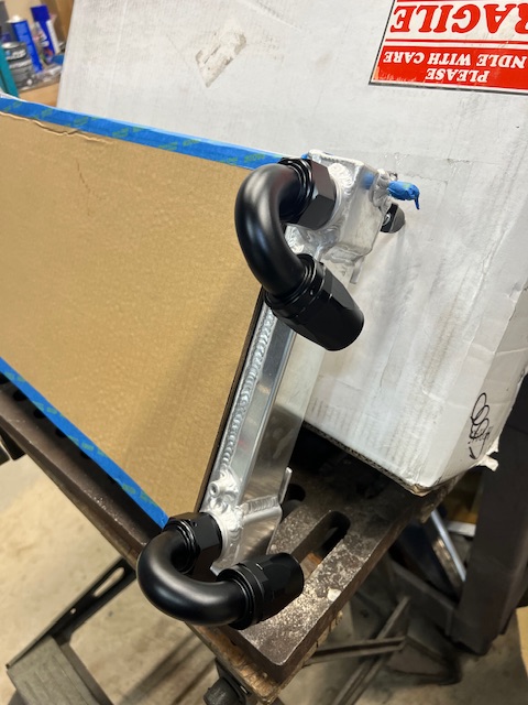 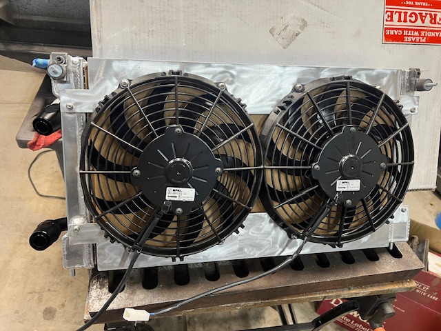 That pretty much sums up where I’m at now. Hoping to finish the hose routing next and start on the heater core build. Happy 914-ing everyone! |
|
|
|
| Cairo94507 |
Mar 13 2025, 06:18 PM
Post
#25
|
|
Michael Group: Members Posts: 10,637 Joined: 1-November 08 From: Auburn, CA Member No.: 9,712 Region Association: Northern California |
Very nice progress. I especially like the new tailpipe opening you made in the valance; nice touch. (IMG:style_emoticons/default/beerchug.gif)
|
|
|
|
| FL000 |
Mar 13 2025, 07:28 PM
Post
#26
|
|
Member Group: Members Posts: 481 Joined: 31-January 12 From: Lancaster, CA Member No.: 14,076 Region Association: Southern California |
I believe the Subarus run pretty cool (compared to my SBC), but consider ducting the radiator to force the air out the bottom. It’ll be more efficient, and help with what looks to be a shallow angle of the radiator.
|
|
|
|
| 914werke |
Mar 13 2025, 08:38 PM
Post
#27
|
|
"I got blisters on me fingers" Group: Members Posts: 11,665 Joined: 22-March 03 From: USofA Member No.: 453 Region Association: Pacific Northwest |
QUOTE(Lilchopshop @ Mar 9 2024, 06:54 AM)  It’s been a while since my last post, but I’ve been chipping away at stuff. Here are some updates. Shifter is mounted Hmm regarding the shifter. Just wondering out loud, if the primary reason for the OE center tunnel is to mount the shifter & contain the rod/linkage, once removed is there a reason not to relocate the cable shift box/monstrosity lowered into that space? |
|
|
|
| Lilchopshop |
Mar 14 2025, 07:50 AM
Post
#28
|
|
Member Group: Members Posts: 111 Joined: 17-February 20 From: New York Member No.: 23,932 Region Association: North East States |
QUOTE(914werke @ Mar 13 2025, 10:38 PM) QUOTE(Lilchopshop @ Mar 9 2024, 06:54 AM) It’s been a while since my last post, but I’ve been chipping away at stuff. Here are some updates. Shifter is mounted Hmm regarding the shifter. Just wondering out loud, if the primary reason for the OE center tunnel is to mount the shifter & contain the rod/linkage, once removed is there a reason not to relocate the cable shift box/monstrosity lowered into that space? Definitely an interesting idea, and one that I may spend time pondering further. I do still need space below the shift mechanism for throttle cable, fuel lines and hydraulic clutch tube. I really don't love the giant boxter shift base either, but I did shorten the shift lever quite a bit and there is some plastic I can remove to reduce the overall bulk of it. Many others have used the shifter from an MR2 which is much less bulky, but I got this boxter shifter cheap and just went with it. |
|
|
|
| East coaster |
Mar 14 2025, 09:18 AM
Post
#29
|
|
Senior Member Group: Members Posts: 1,932 Joined: 28-March 03 From: Millville, NJ Member No.: 487 Region Association: None |
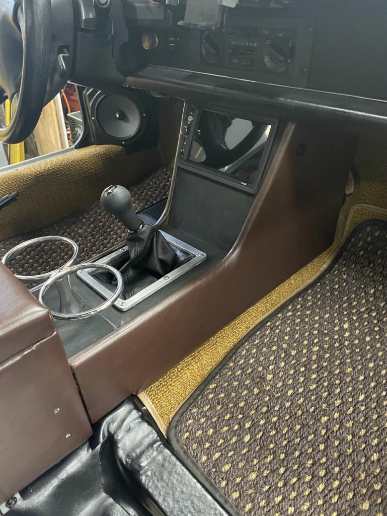
I hid mine under a custom center console. Mine is the MR2 shifter but similar height with the mounting bracket.
  |
|
|
|
| 76-914 |
Mar 14 2025, 09:15 PM
Post
#30
|
|
Repeat Offender & Resident Subaru Antagonist Group: Members Posts: 13,884 Joined: 23-January 09 From: Temecula, CA Member No.: 9,964 Region Association: Southern California |
You should be able to cool the 2.5 with a much smaller opening unless you run AC in the south and drive in StopnGo traffic. Nice work
|
|
|
|
| Lilchopshop |
Mar 14 2025, 09:35 PM
Post
#31
|
|
Member Group: Members Posts: 111 Joined: 17-February 20 From: New York Member No.: 23,932 Region Association: North East States |
QUOTE(East coaster @ Mar 14 2025, 11:18 AM) I hid mine under a custom center console. Mine is the MR2 shifter but similar height with the mounting bracket. Yep. I’m hoping to do something like that. Love your whole build, btw! |
|
|
|
| Lilchopshop |
Apr 17 2025, 06:19 AM
Post
#32
|
|
Member Group: Members Posts: 111 Joined: 17-February 20 From: New York Member No.: 23,932 Region Association: North East States |
April '25 update:
I've been able to spend several hours a week on the project. Progress feels slow, but I'm moving forward, (I think?). I'm still working in the frunk trying to figure out all of the details for radiator mounting, hose routing, ducting, wire routing, spare tire mounting, etc. I feel like I've been spending a lot more time staring at the car and trying to make decisions on all of this stuff as opposed to actually doing the work. This part of the project definitely has me questioning my choice to convert to a water-cooled engine. Anyway... here's where I'm at: After removing both structural panels between the front cross panel and the wheel wells, I welded some new metal to them and straightened them out as best as I could to better repair the previous collision damage repair. Shot these with some self-etch primer and welded them back in place. 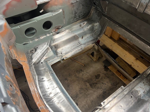 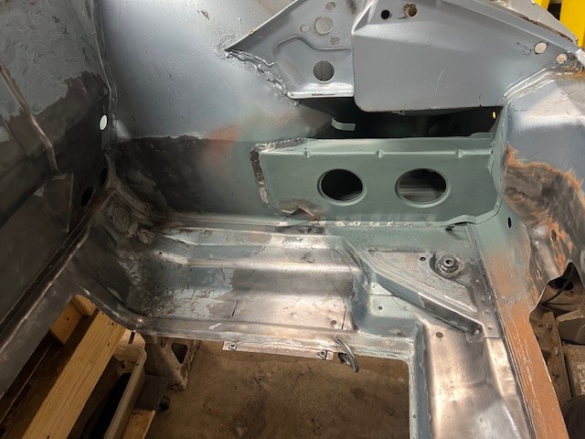 I then made a cross-member to support the bottom of the radiator. I went round and round on the design of this part and the best way to attach this to the chassis. I don't want the final product to look like a cloogey conversion so I'm trying to make the modifications look like they belong in the car to the best of my ability. Not sure I totally hit the mark on this, but I'm satisfied enough. 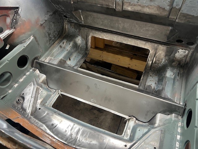 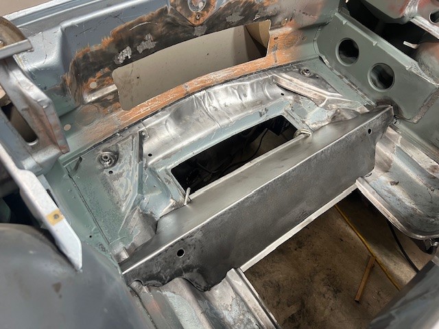 It's a little tricky to tell what you're looking at here, but this is the underside of the radiator support cross member. Since this piece gets in the way of the wires that route from the fuse panel to the headlights/turn-signals/horns, I decided to keep the bottom open so that I can route the wires through this over to the passenger side headlight/turn-signal/horn. I will make some sort of flat cover that attaches to the underside of this so that I can access this area from below the car but still keep the road grime and water out of here. The mounting tabs in the center and welded nuts on either end are for the attachment of this future cover. The sheet-metal tabs are retainers for the wire bundle that will run from drivers side to passenger side (trying to duplicate the factory sheet-metal wire retainers). 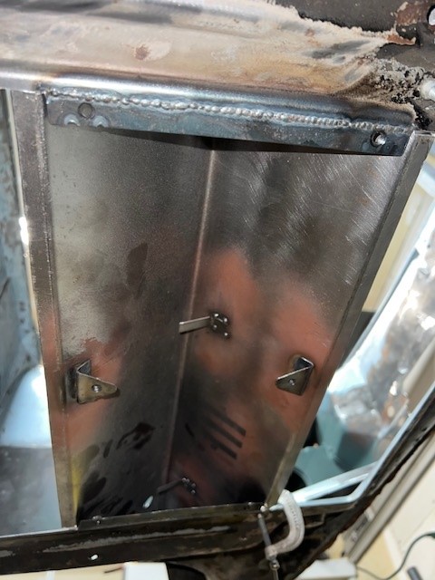 Finally, the cross-member is welded in (not the prettiest welding, my gaps were too big) and I filled in the hole in the front of the frunk floor. I was feeling pretty good about my progress at this point so I invited my wife out the garage so that she could marvel at my work. Her only comment... "when are you going to get to the pretty stuff?" (IMG:style_emoticons/default/dry.gif) 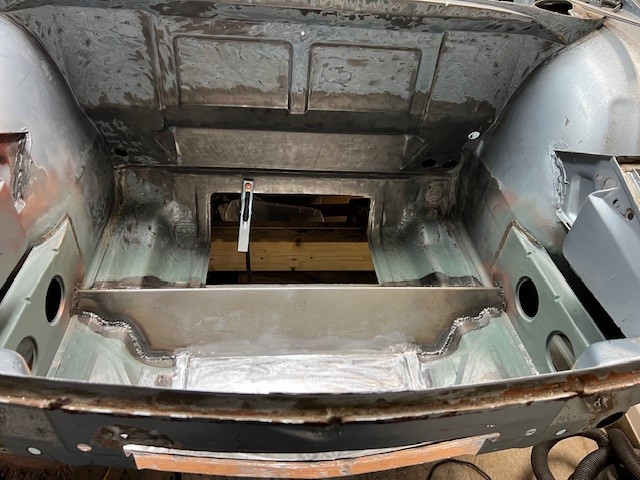 Lastly, the progress on the hose routing... I'm pretty sure I'm going to get some negative feedback on this, but I've chosen to route BOTH coolant hoses through the driver's side longitudinal. Various factors contributed to this decision. I don't like the idea of going under the car (too much chance for damage, IMO) and based on the radiator configuration/location I have, I think this path makes the most sense. Plus, the driver's side longitudinal is currently wide open because of my rust repairs, so this makes it easy to remove the heater ducting and install two individual conduits in there to protect/insulate the hoses and make it easier to fish the hoses through during final assembly or if I ever need to replace them in the future. I plan to make a removable cover that will conceal/protect the exposed hoses in the driver's foot well. I know that having two big, hot hoses right near the driver's seat might make the ride a little warm. I'm really hoping it won't be unbearable! 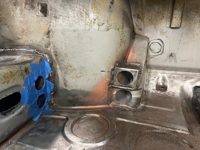 Here is a picture looking down into the area below the gas tank. The two coolant hoses will run in the little cavity that sits right under the torsion bar. The cavity wasn't quite big enough, so I cut it open and flared out the one side so that the hoses could exit next to each other in the frunk. The oval-shaped hole has since been filled in with a domed piece of metal that gives the hoses just a little more room at the bend. I made sure none of this stuff will interfere with the gas tank or the torsion bar. 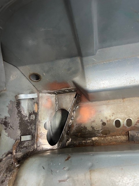 And the holes in the frunk where the hoses will exit. I'll use rubber grommets at all the holes where the hoses pass through. 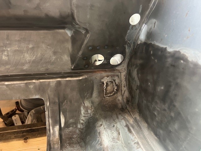 That's it for now. Thanks for looking! |
|
|
|
| East coaster |
Apr 17 2025, 09:16 AM
Post
#33
|
|
Senior Member Group: Members Posts: 1,932 Joined: 28-March 03 From: Millville, NJ Member No.: 487 Region Association: None |
Looking good!
|
|
|
|
| slowrodent |
Apr 17 2025, 10:00 AM
Post
#34
|
|
Member Group: Members Posts: 230 Joined: 29-February 20 From: Tucson/Oro Valley Member No.: 23,981 Region Association: Southwest Region |
Very very nice work.... (IMG:style_emoticons/default/beerchug.gif)
|
|
|
|
| Lilchopshop |
Jan 21 2026, 05:00 PM
Post
#35
|
|
Member Group: Members Posts: 111 Joined: 17-February 20 From: New York Member No.: 23,932 Region Association: North East States |
Well, it’s been a while since my last update here. As usual, I’m easily distracted and the 914 project always takes the back seat when higher priority projects arise. In the interim however, I’ve been busy…
R&R’d the rear suspension and Rebuilt the engine on my wife’s ghia vert. 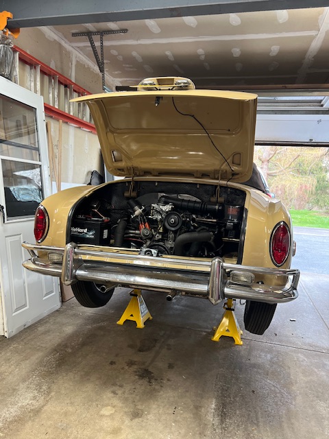 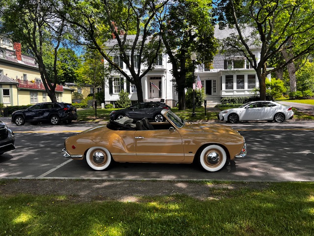 Built a “proper” welding table that I absolutely love! 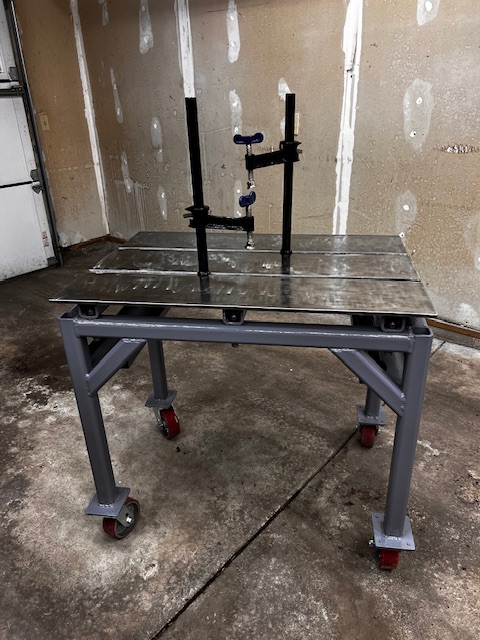 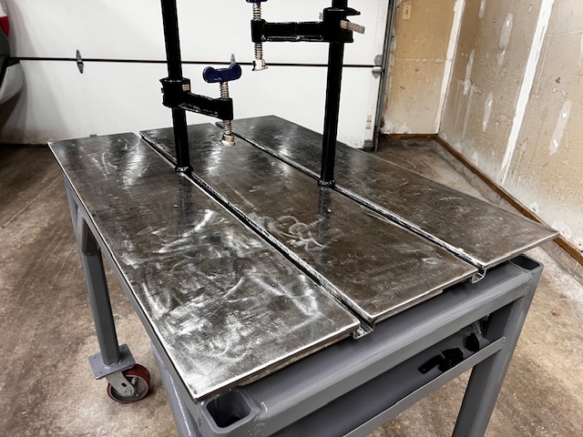 Restored an OLD South Bend lathe. 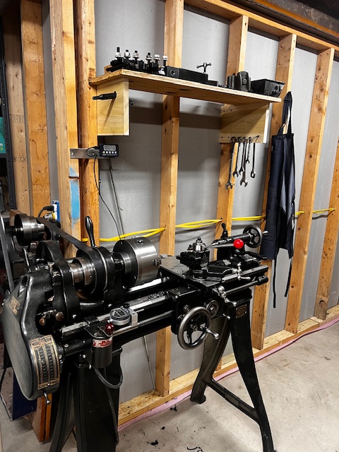 And took some fun trips! 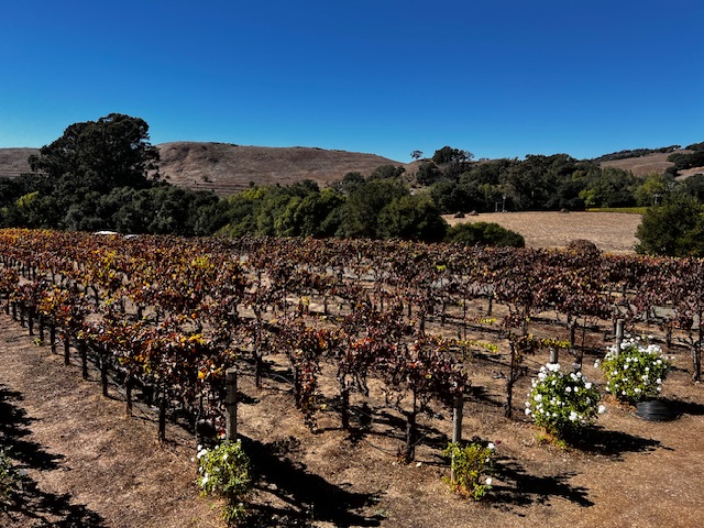 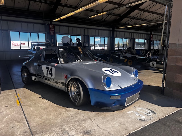 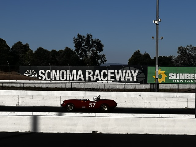 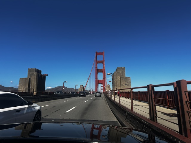 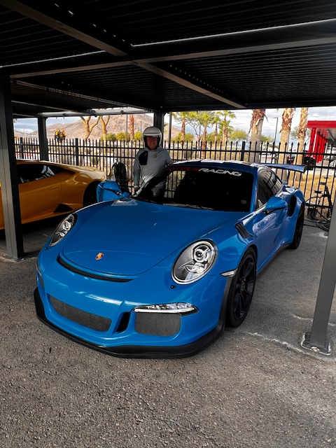 Attached image(s) 
|
|
|
|
| Lilchopshop |
Jan 21 2026, 05:52 PM
Post
#36
|
|
Member Group: Members Posts: 111 Joined: 17-February 20 From: New York Member No.: 23,932 Region Association: North East States |
Enough of that. Here’s the progress on the car!
My focus has still been on the cooling system. Specifically, the radiator mounting and shroud. So, I cut a hole in the bumper and built a “tunnel” through the bumper and the frunk front panel. Right now the tunnel is just tack-welded in case I find a reason to alter it later. Eventually it will get trimmed so that it is flush-ish with the bumper and front spoiler. I’m designing a custom plastic grille that will attach to the tunnel at the bumper/spoiler opening.  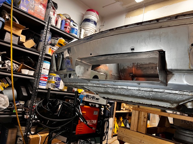 Then, I needed to finalize the radiator mounting so that I could fabricate the shroud. I made some brackets that I welded to the gas tank wall (or whatever you call that part). I’m using rubber bushings/mounts at all radiator mounts to reduce stress. 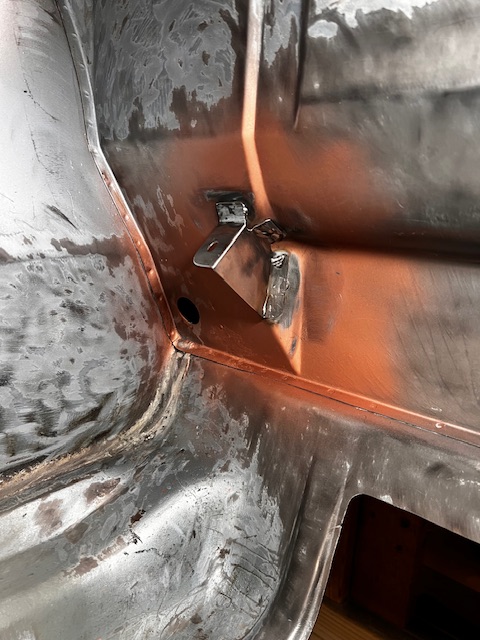 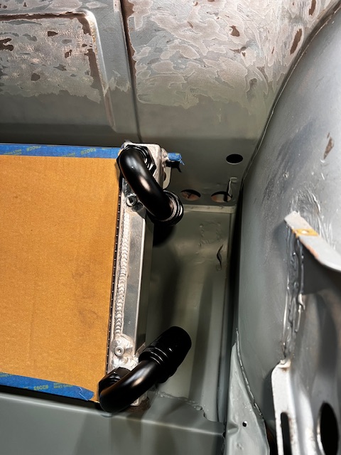 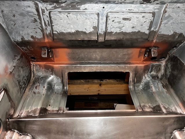  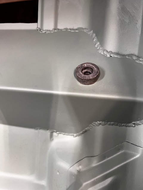 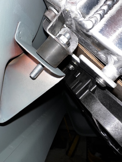 Attached image(s)  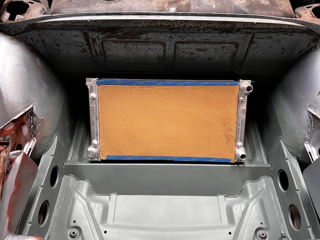
|
|
|
|
| Lilchopshop |
Jan 21 2026, 06:35 PM
Post
#37
|
|
Member Group: Members Posts: 111 Joined: 17-February 20 From: New York Member No.: 23,932 Region Association: North East States |
With the radiator and tunnel in place, I mocked up a cardboard shroud and tested it with my cardboard spare tire.
   Then, I decided it was time to test out the new bead roller that I bought over a year ago just for this part of the project. It’s pretty easy to use, but man I wish it had a motor and a foot pedal! 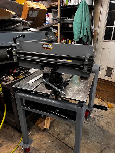 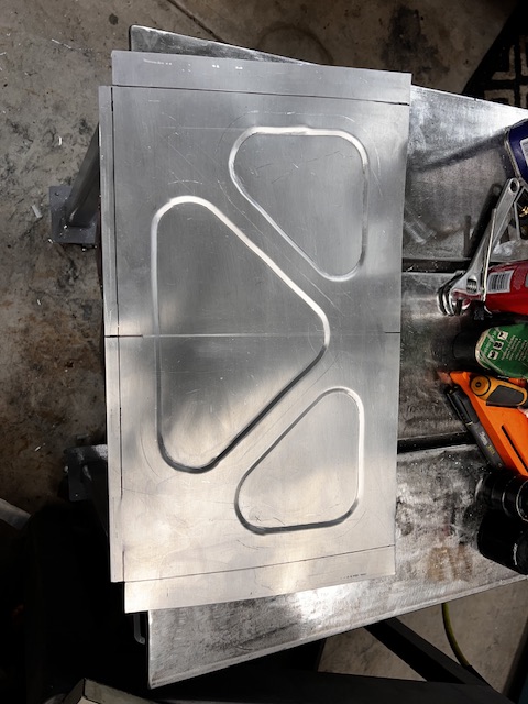 It only took me a few hours to get comfortable with the bead roller and then I started making the parts for the shroud. I’m using .040” 5052 Aluminum. It bends well, but it’s hard to get crisp bends. I decided to use rivets to join the pieces together. I kinda like the look of rivets in aluminum, so this is how I joined the pieces of the shroud. 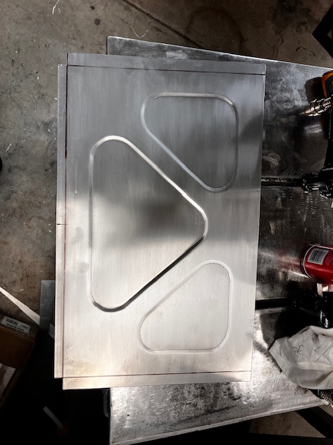 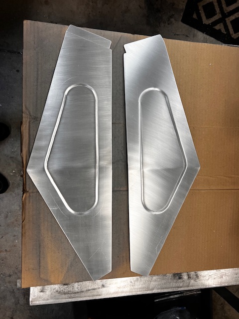 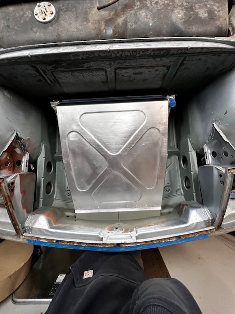 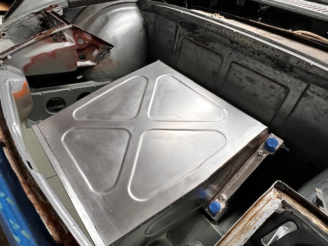 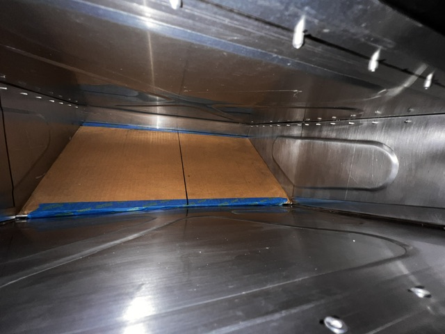 Next up, I’m making the parts that will attach the shroud to the radiator. Thanks for looking! Aaron |
|
|
|
| worn |
Jan 21 2026, 06:43 PM
Post
#38
|
|
Winner of the Utah Twisted Joint Award Group: Members Posts: 3,597 Joined: 3-June 11 From: Madison, WI and North Bend WA Member No.: 13,152 Region Association: Upper MidWest |
Very nice. I see quality in every post.
|
|
|
|
| tygaboy |
Jan 21 2026, 07:28 PM
Post
#39
|
|
914 Guru Group: Members Posts: 5,826 Joined: 6-October 15 From: Petaluma, CA Member No.: 19,241 Region Association: Northern California |
Lovely bead work! Looks REALLY good. (IMG:style_emoticons/default/aktion035.gif)
|
 |
|
| Ninja |
Jan 21 2026, 08:14 PM
Post
#40
|
|
Member Group: Members Posts: 213 Joined: 25-September 25 From: Granbury Texas Member No.: 29,004 Region Association: Southwest Region |
QUOTE(Lilchopshop @ Jan 21 2026, 06:35 PM) With the radiator... Next up, I’m making the parts that will attach the shroud to the radiator. Thanks for looking! Aaron Ninja approved! (IMG:style_emoticons/default/ninja.gif) Really nice work, world class! (IMG:style_emoticons/default/first.gif) Plenty BIG room for a condenser, awesome side clearance for hoses! That Suby came with a pretty good compressor originally. You might not need the AC but I do down here... (IMG:style_emoticons/default/stirthepot.gif) |
|
|
|
|
6 User(s) are reading this topic (5 Guests and 0 Anonymous Users)
1 Members: tygaboy

|
Lo-Fi Version | Time is now: 19th May 2026 - 10:36 PM |
Invision Power Board
v9.1.4 © 2026 IPS, Inc.