|
|
|
Porsche, and the Porsche crest are registered trademarks of Dr. Ing. h.c. F. Porsche AG.
This site is not affiliated with Porsche in any way. Its only purpose is to provide an online forum for car enthusiasts. All other trademarks are property of their respective owners. |
|
|

  |

| friethmiller |
 Dec 19 2023, 03:46 PM Dec 19 2023, 03:46 PM
Post
#61
|
|
Senior Member  Group: Members Posts: 1,358 Joined: 10-February 19 From: Austin, TX Member No.: 22,863 Region Association: Southwest Region |
QUOTE(Root_Werks @ Dec 19 2023, 12:30 PM)  Really coming along! Thanks for sharing all the pics. We like following build/repair threads around here. (IMG:style_emoticons/default/welder.gif) Thanks Dan! There's a lot here on 914World, for sure. Here's a link to a site where I learned how to rebuild this part of the car. It's an older site but still up/helpful. https://motorsport.zyyz.com/project_914_03_04.htm |
   |

 
|
| friethmiller |
Dec 19 2023, 04:05 PM
Post
#62
|
|
Senior Member Group: Members Posts: 1,358 Joined: 10-February 19 From: Austin, TX Member No.: 22,863 Region Association: Southwest Region |
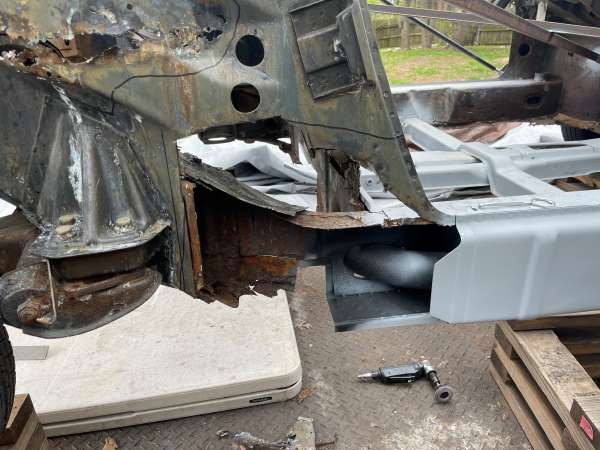
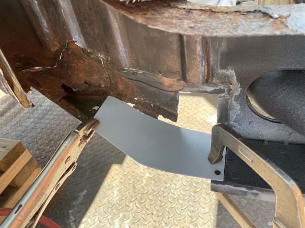
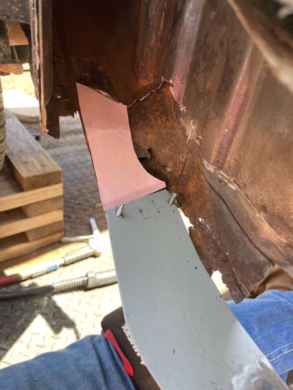
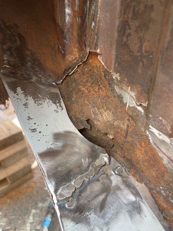
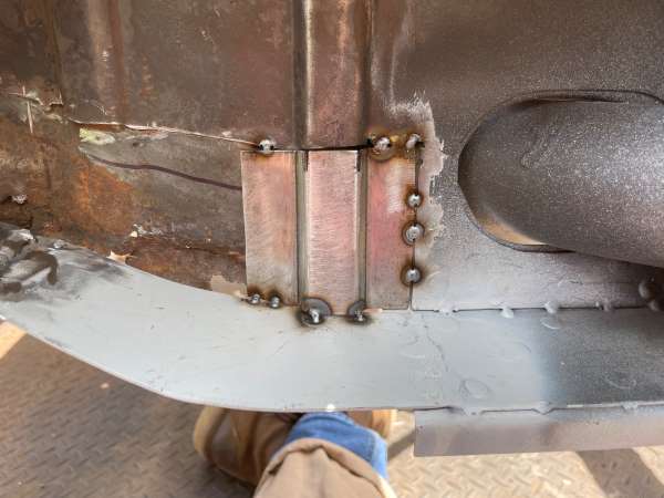
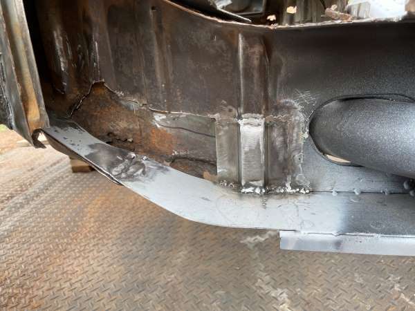
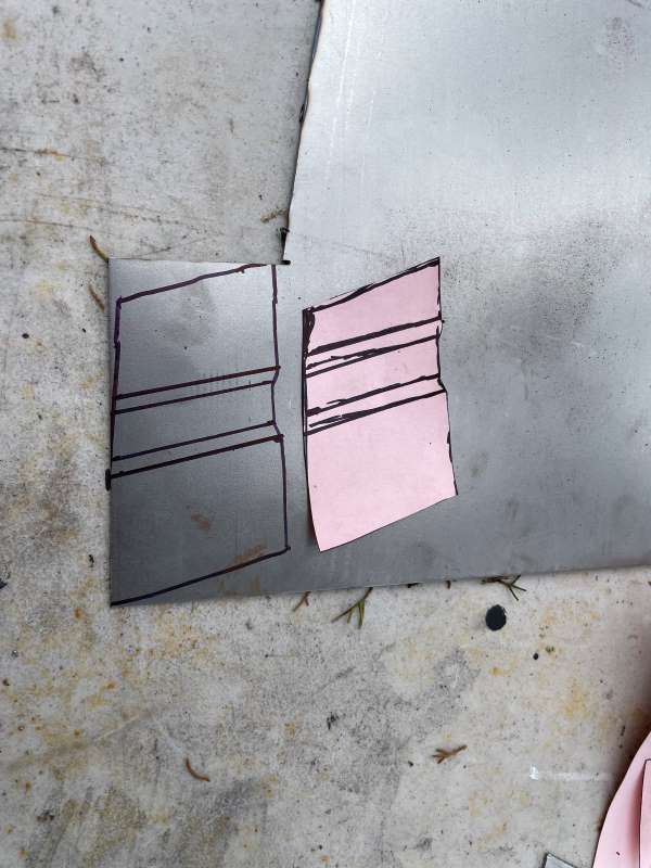
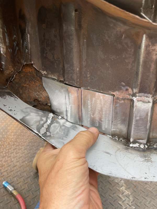
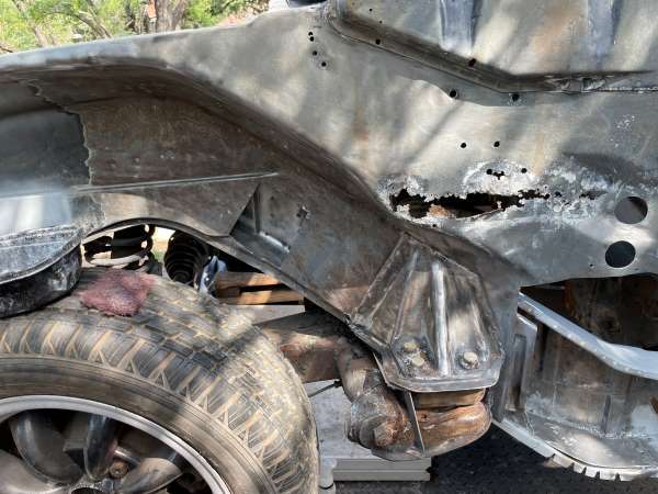
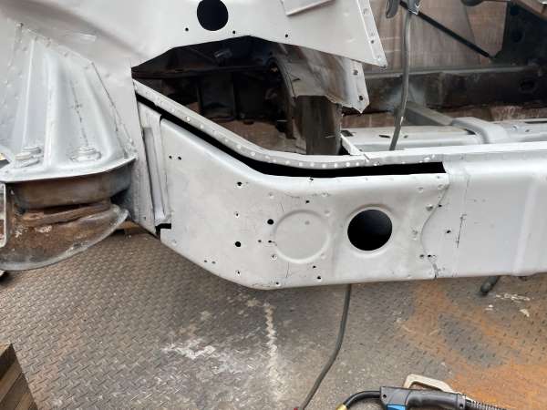
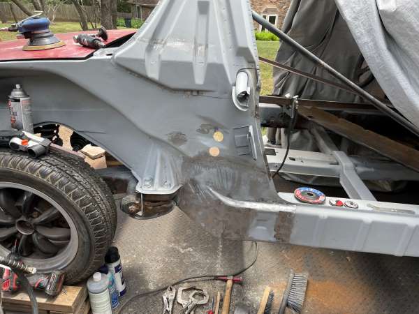
Outer Hell Hole Repair (4/2023): Here we go! My plan was to rebuild the inner structural metal first using the correct gauge metal and then remove and replace the outer sheet metal. To do this, I first cut a piece to go from the bottom of the longitudinal to some good metal up the "frame rail". You can see the use of my daughter's construction paper to set the shape of several of the repair pieces. Once the bottom was in place, I then form the missing side walls using my metal brake to match the shape as best I could - welding it in piece-by-piece. I then finished this part of the repair with a few formed pieces that go around the engine mount intrusion. Note: Nobody will see this repair so it's all about making it strong/rigid. Also, I used a ball jack to support the end of the longitudinal before cutting any metal out of the car., just in case.
             |
|
|
|
| friethmiller |
Dec 19 2023, 07:30 PM
Post
#63
|
|
Senior Member Group: Members Posts: 1,358 Joined: 10-February 19 From: Austin, TX Member No.: 22,863 Region Association: Southwest Region |
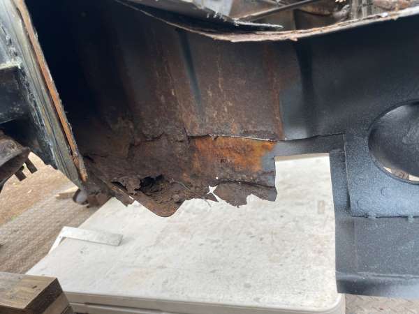
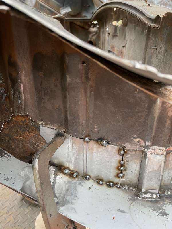
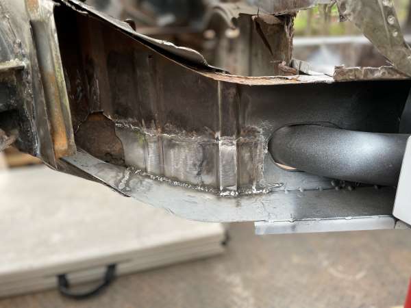
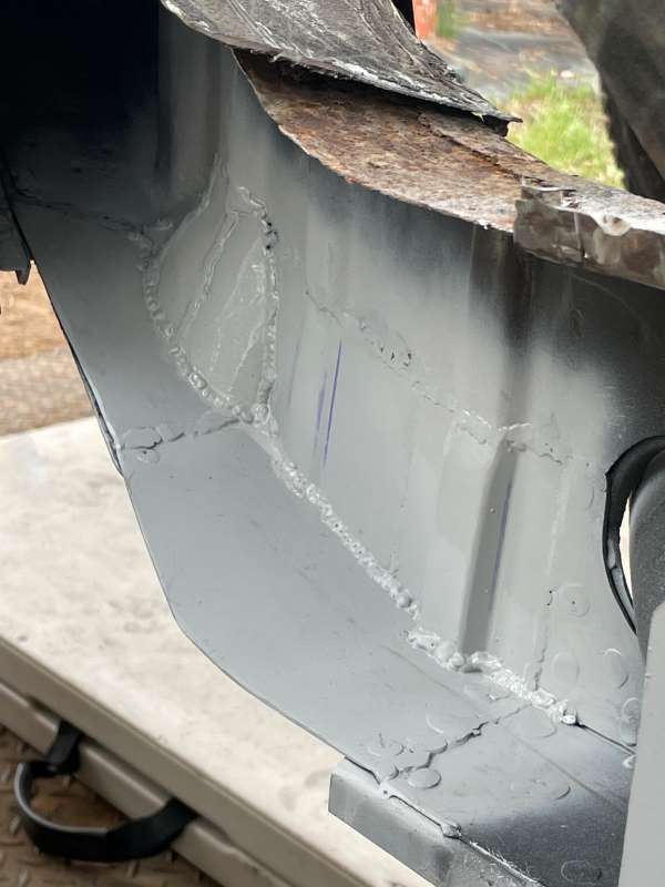
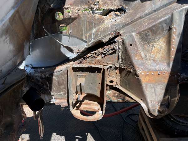
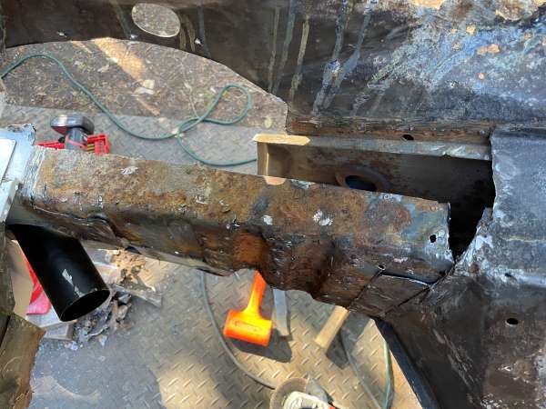
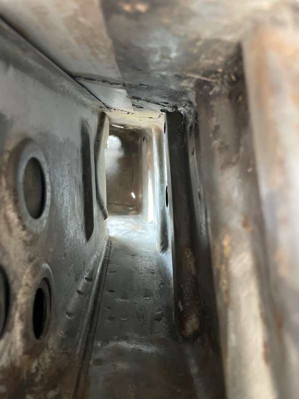
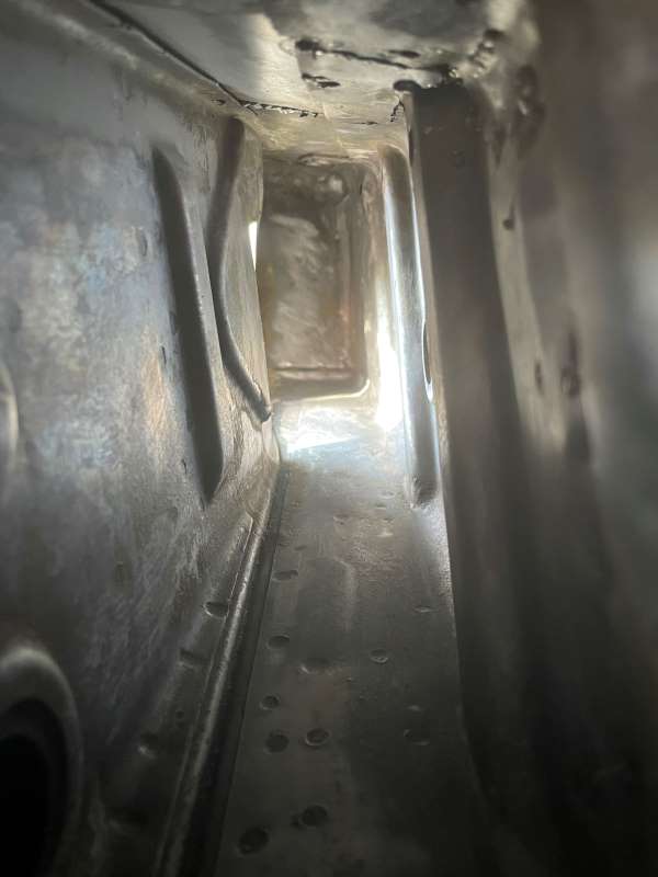
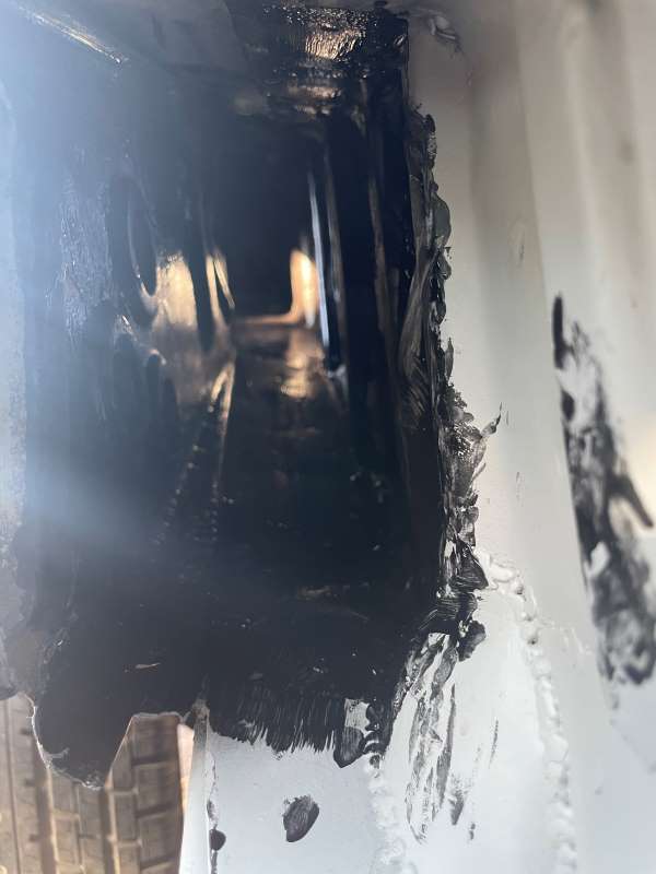
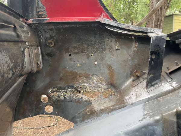
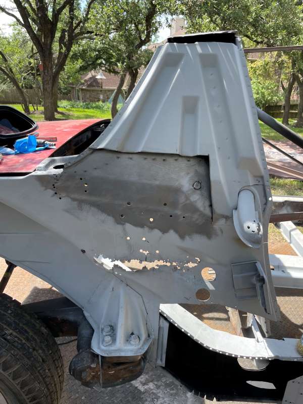
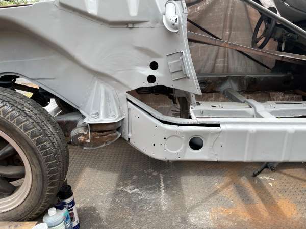
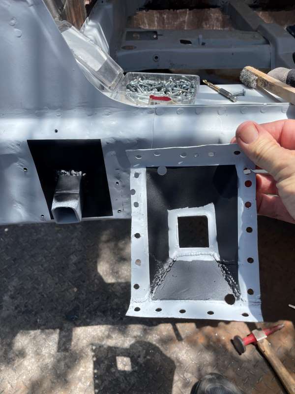
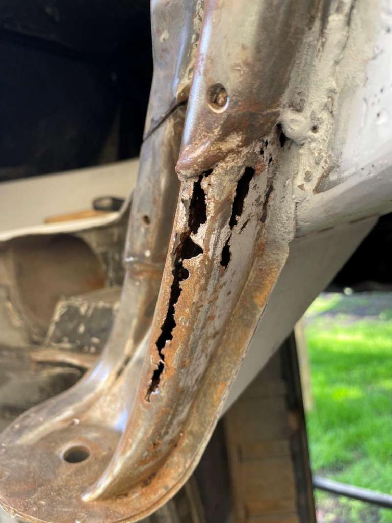
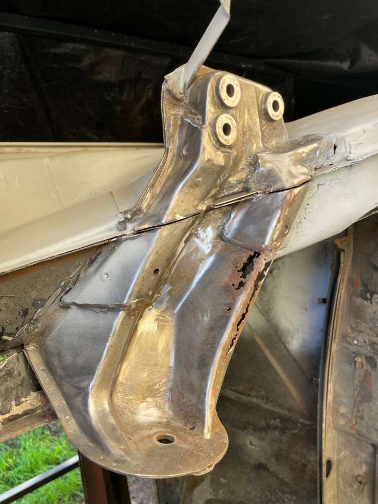
Inner Hell Hole Repair (5/2023): The first photo shows the damage! Previous repairs were present here and there. After removing the scab metal, I removed the engine mount to expose the hidden horror. After cutting away more metal I exposed a majority of the rail. Here you can see the reconstructed inner rail (gray).
    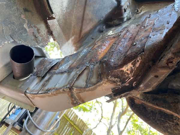 With a little wire wheel and rust converter, I was able to get things looking a bit better. I didn't like the looks of the top part of the inner rail so I decided to replace a section with new metal. This repair was straight forward. 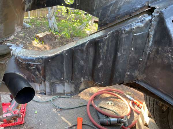 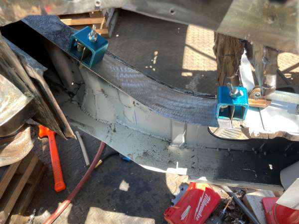 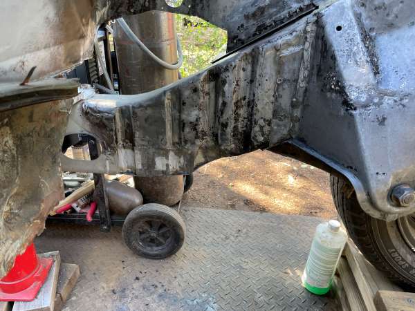 Next, with the inner rail prep'd/repaired, I started forming the sheet metal pieces I would need to reskin this entire section. Note the use of the RD repair piece to help set the edge on the fender side. Once I puzzled the pieces in, everything was removed, painted with weld-thru primer or frame rail paint prior to being welded in. After grinding the welds the bottom pieces were then formed and welded in place. More photos coming in a few days... 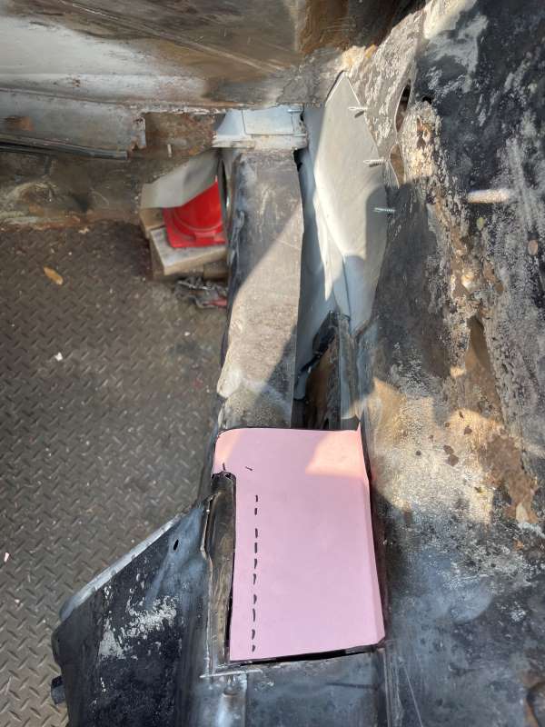 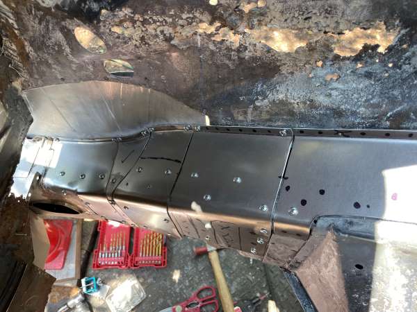 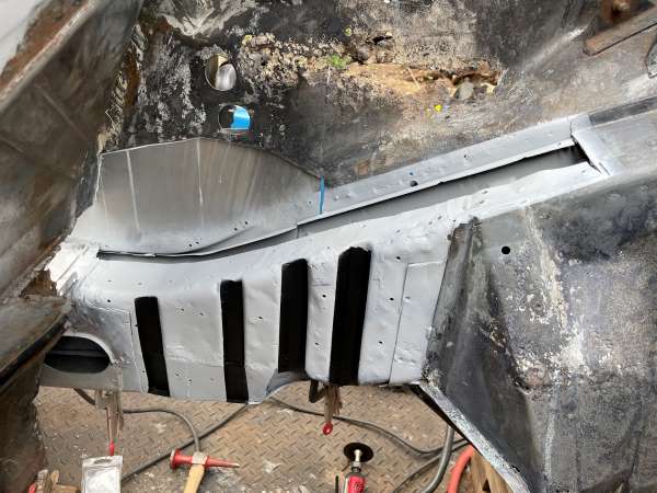 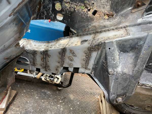 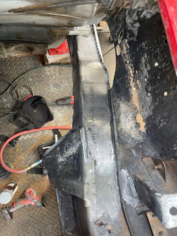 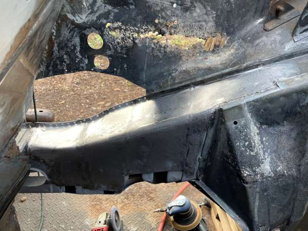 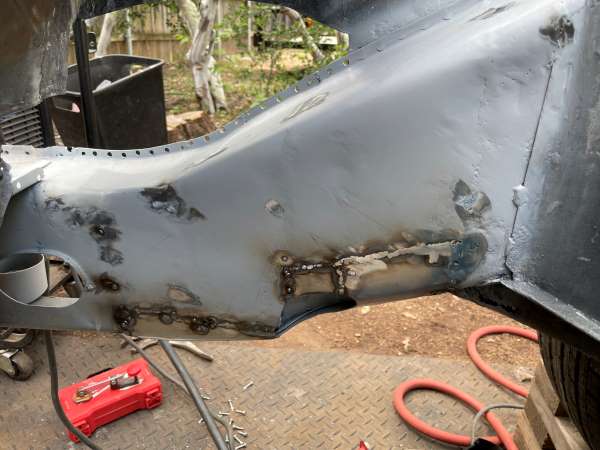 |
|
|
|
| bkrantz |
Dec 19 2023, 07:50 PM
Post
#64
|
|
914 Guru Group: Members Posts: 8,733 Joined: 3-August 19 From: SW Colorado Member No.: 23,343 Region Association: Rocky Mountains |
Nice!
(Once again, I have to wonder what the Porsche/Karmann engineers were thinking when they concocted this 12 layer design--and what the guys on the factory floor thought.) |
|
|
|
| friethmiller |
Dec 20 2023, 11:59 AM
Post
#65
|
|
Senior Member Group: Members Posts: 1,358 Joined: 10-February 19 From: Austin, TX Member No.: 22,863 Region Association: Southwest Region |
QUOTE(bkrantz @ Dec 19 2023, 07:50 PM) Nice! (Once again, I have to wonder what the Porsche/Karmann engineers were thinking when they concocted this 12 layer design--and what the guys on the factory floor thought.) Good questions. The heavier internal metal doesn’t often meet with other panels. It’s just providing strength to the lighter (18 gauge) sheet metal. I guess that keeps your welded contacts thinner - easier to weld on the assembly line. |
|
|
|
| Superhawk996 |
Dec 20 2023, 02:13 PM
Post
#66
|
|
914 Guru Group: Members Posts: 7,935 Joined: 25-August 18 From: Woods of N. Idaho Member No.: 22,428 Region Association: Galt's Gulch |
QUOTE(bkrantz @ Dec 19 2023, 09:50 PM) Nice! (Once again, I have to wonder what the Porsche/Karmann engineers were thinking when they concocted this 12 layer design--and what the guys on the factory floor thought.) The use of the inner corrugated stiffener is the part of the secret to making the 914’s light weight chassis. The stamped stiffening darts add section thickness that stiffens the inner reinforcement panel far more than could be achieved by using a much thicker flat panel. Stiffness through geometry rather than mass. The kink in the longitudinal as it transitions from floor pan up into the engine bay is structurally weak in vertical bending. Addition of the corrugated inner stiffener really helps stiffen that critical area. This technique of localized section stiffness is now commonly used in all modern unibody designs. Gotta’ remember how advanced this was at a time when lots of domestic iron was still heavy, body on frame construction. |
|
|
|
| Superhawk996 |
Dec 20 2023, 02:22 PM
Post
#67
|
|
914 Guru Group: Members Posts: 7,935 Joined: 25-August 18 From: Woods of N. Idaho Member No.: 22,428 Region Association: Galt's Gulch |
That’s quite a project - (IMG:style_emoticons/default/aktion035.gif)
(IMG:style_emoticons/default/smilie_pokal.gif) Keeping another one on the road |
|
|
|
| technicalninja |
Dec 20 2023, 02:45 PM
Post
#68
|
|
Advanced Member Group: Members Posts: 2,531 Joined: 31-January 23 From: Granbury Texas Member No.: 27,135 Region Association: Southwest Region |
You should make a "Project Book" in a paper form to document all the exquisite work for the possibility of car shows and to increase the value if you ever decide to sell.
The car will be impressive, but the work done to bring it back is FAR more impressive in my book. People who have done this before will be the ones who are the most "blown away" by your level of competence. |
|
|
|
| friethmiller |
Dec 21 2023, 09:15 AM
Post
#69
|
|
Senior Member Group: Members Posts: 1,358 Joined: 10-February 19 From: Austin, TX Member No.: 22,863 Region Association: Southwest Region |
Up in Chicago for a few days. I’ll post more when I get back. The whole inner fender repair is next, followed by the rear body panel to finish up the trunk, and back into the engine bay for the inner suspension console, battery tray, and engine mount. That will catch us up to present day.
|
|
|
|
| friethmiller |
Dec 21 2023, 10:09 AM
Post
#70
|
|
Senior Member Group: Members Posts: 1,358 Joined: 10-February 19 From: Austin, TX Member No.: 22,863 Region Association: Southwest Region |
QUOTE(Superhawk996 @ Dec 20 2023, 02:13 PM) QUOTE(bkrantz @ Dec 19 2023, 09:50 PM) Nice! (Once again, I have to wonder what the Porsche/Karmann engineers were thinking when they concocted this 12 layer design--and what the guys on the factory floor thought.) The use of the inner corrugated stiffener is the part of the secret to making the 914’s light weight chassis. The stamped stiffening darts add section thickness that stiffens the inner reinforcement panel far more than could be achieved by using a much thicker flat panel. Stiffness through geometry rather than mass. The kink in the longitudinal as it transitions from floor pan up into the engine bay is structurally weak in vertical bending. Addition of the corrugated inner stiffener really helps stiffen that critical area. This technique of localized section stiffness is now commonly used in all modern unibody designs. Gotta’ remember how advanced this was at a time when lots of domestic iron was still heavy, body on frame construction. Good info! I’ll try, at a minimum, to mimic the factory metal as I move along. |
|
|
|
| friethmiller |
Dec 23 2023, 09:00 PM
Post
#71
|
|
Senior Member Group: Members Posts: 1,358 Joined: 10-February 19 From: Austin, TX Member No.: 22,863 Region Association: Southwest Region |
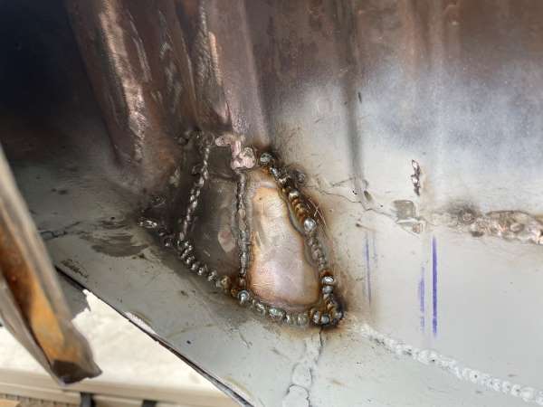
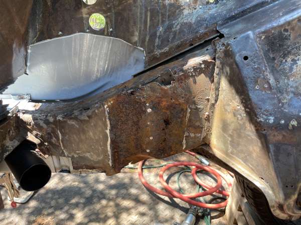
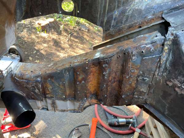
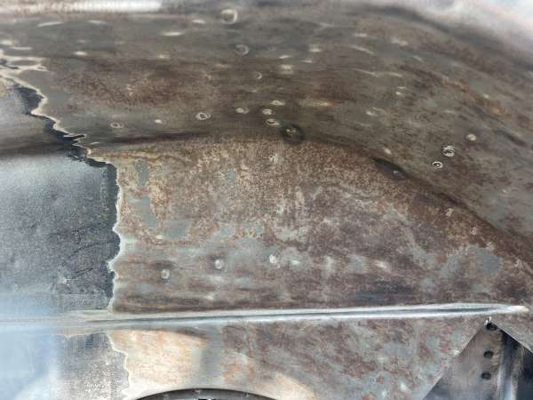
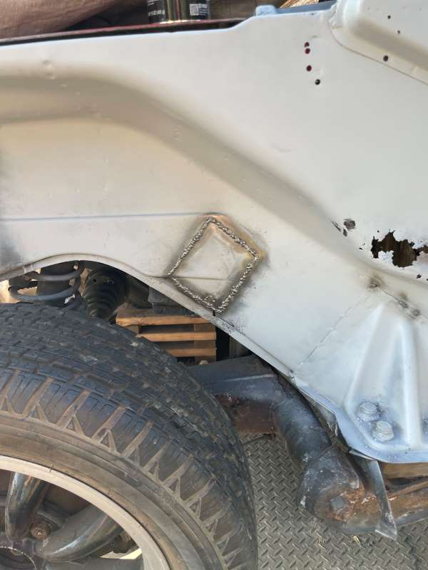
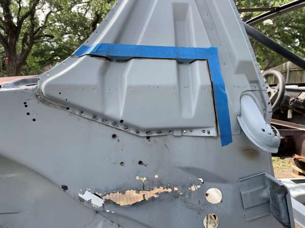
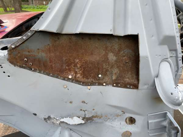
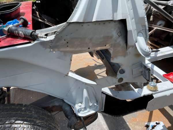
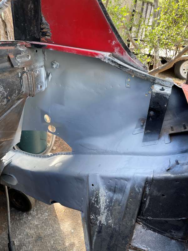
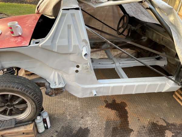
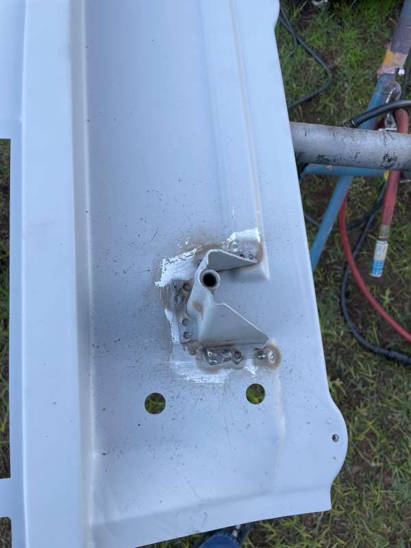
Inner Rail/Fender Repair - Part 1 (6/2023): After a few weeks away, I spent some time cleaning up the inside of the main support rail. There was already a 1/2 inch hole drilled behind the outer suspension console by the previous owner so I decided to just open up a larger hole to aid in the process. With a square cut out of the inner fender, I was able to better clean, wire-wheel, and rust-treat the entire support rail. I also removed the old black paint on the inner fender. A few of the pictures show the crazy amount of surface rust that has gotten underneath the paint over the years. It must be completely removed. Luckily, it's fairly easy to do with a phosphorus-based etching treatment. All of this prep had to be done prior to patching up the rust holes in the inner fender and completing the hell hole repairs.
        |
|
|
|
| friethmiller |
Dec 23 2023, 09:26 PM
Post
#72
|
|
Senior Member Group: Members Posts: 1,358 Joined: 10-February 19 From: Austin, TX Member No.: 22,863 Region Association: Southwest Region |
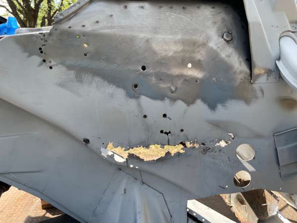
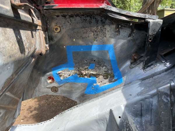
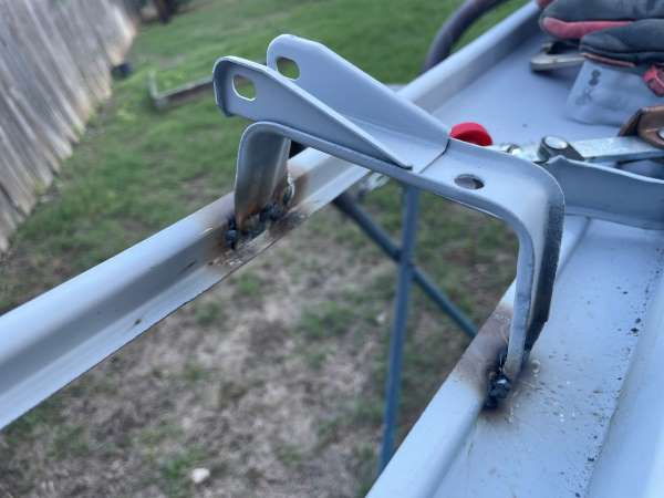
Inner Fender Repair - Part 2 (7/2023): In the initial set of photos, you can see how poor the metal was next to the battery tray (no longer present), the shabby rivet repair to the trunk hinge cup, and several extra holes that were used for God knows what. To gain access to both sides of the metal here, I decided to remove the lower section of the inner rollbar support piece. This was removed by drilling out spot-welds and a few cuts. The exposed bit of surface rust was easily removed.
     |
|
|
|
| friethmiller |
Dec 23 2023, 09:38 PM
Post
#73
|
|
Senior Member Group: Members Posts: 1,358 Joined: 10-February 19 From: Austin, TX Member No.: 22,863 Region Association: Southwest Region |
Inner Fender Repair - Part 3 (7/2023): The following photos show the repair to the metal around the batter tray and the replacement of the rollbar support piece after filling several, ad hoc drill holes.
      |
|
|
|
| friethmiller |
Dec 24 2023, 08:37 AM
Post
#74
|
|
Senior Member Group: Members Posts: 1,358 Joined: 10-February 19 From: Austin, TX Member No.: 22,863 Region Association: Southwest Region |
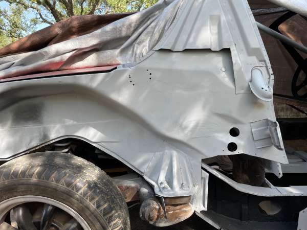
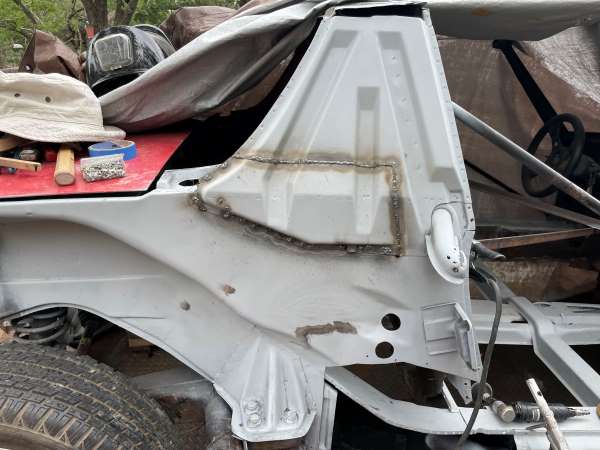
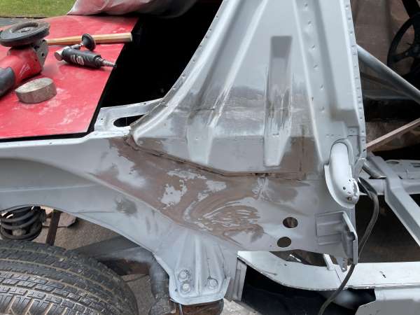
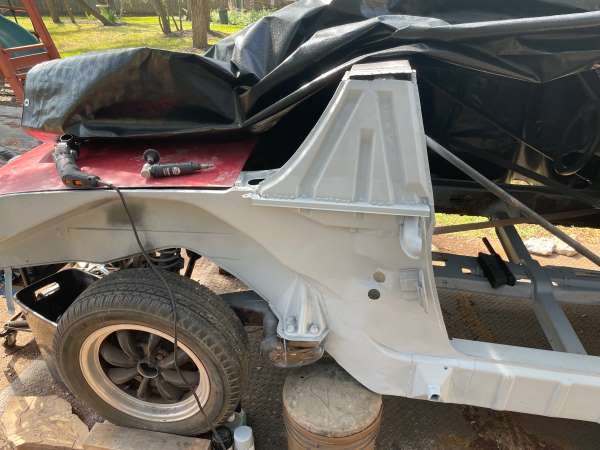
Inner Fender Repair - Part 4 (7/2023): With the inner support metal removed from an inner wheelhouse repair piece I picked up off of eBay, I trimmed and fitted it to the body. It took a while to make sure that the external sheet metal (skin) that has the jack point base was located at the proper measurement. I even mocked in the jack post and outer rocker panel to double check alignment. There's a bit of wiggle room here but you want to get it pretty close. Once satisfied, I welded the internal structure in place. Next, the outer sheet metal skin was aligned and welded. Adding on the jack post, repaired support plate, and the little fender support piece to the roll bar support, the repair was considered complete. Note: I also patched up the air vent tube that had a bit of rust damage.
         |
|
|
|
| friethmiller |
Dec 24 2023, 11:22 AM
Post
#75
|
|
Senior Member Group: Members Posts: 1,358 Joined: 10-February 19 From: Austin, TX Member No.: 22,863 Region Association: Southwest Region |
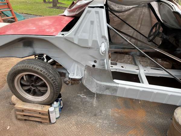
Rotisserie (10/2023): Having completed the repairs I thought necessary to stiffen up the chassis on the LE, I went ahead a built another rotisserie from scratch. Unfortunately, I had sold the previous rotisserie that I had made for my other 914 a few years ago - 'cause I never thought I need it again (IMG:style_emoticons/default/huh.gif) However, I did employ a few "lessons learned" from the last one like: using a drill press for the support bar connection holes on the hoops, and properly cleaning and painting ALL of the metal. Keeping your hands free of that dirty, oily coating is really the way to go.
So, using the same Restoration Design blueprints, I went forward with the build. I ordered/picked up 12 pieces of 12' X 1 1/4" square tubing along with several scrap pieces of 1/2" plate for the casters and the for the four mounting points on the car. BTW, the casters were purchased off amazon for less than $100. I actually only used 10 pieces of tubing for the rotisserie, the other two pipes were saved for an engine test stand that I will be building later. 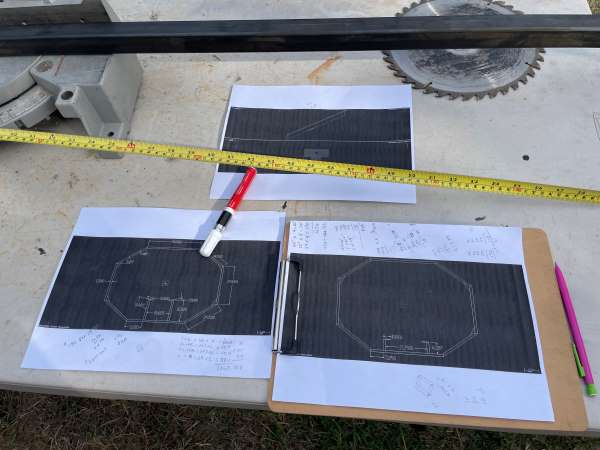 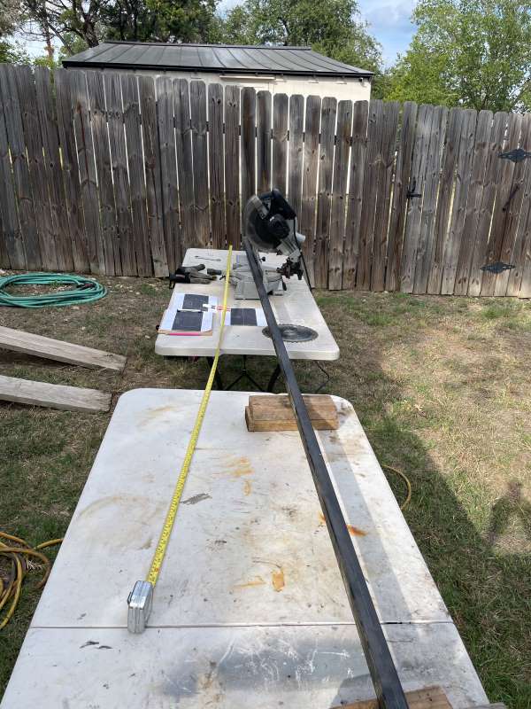 One thing to note about the RD plans is the fact that the angles listed for the rear hoop's mount to the transmission support tunnel are 180 degrees out. I also think additional support metal should be added to the mounting points, which is easy to do with some of the leftover metal scrap. The following pics show how I used my old flux-core welder to build the hoops that were cut, cleaned, and primed. This process is easy to do based on the drawings. I used Simple green to clean all the pipe and painted everything (once dry) with some self-etching metal primer. I would also recommend welding the hoops with the aid of the flat garage floor, like I did. 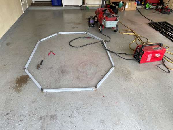 Back outside, I finished any necessary welding on the hoops and began the process of constructing the front and rear mounting points. Once completed, I painted the hoops with some cheap black spray paint. I then decided to add some additional bracing and welded two 6" plates for the casters to the bottom of each hoop. Sorry, I don't have a good picture of the front hoop's mount to the 914's Aux Support bar that is utilized with this design. I also cut the 8 long connecting bars to length and added a 2 1/2" piece of angle iron to each end. A hole was later drilled through each bar end to secure each bar to both hoops. 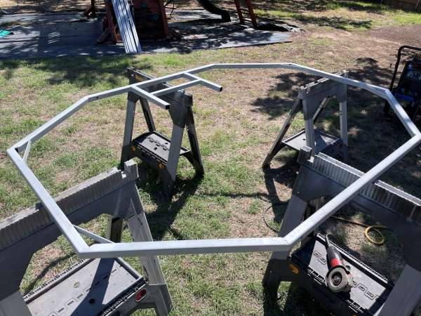 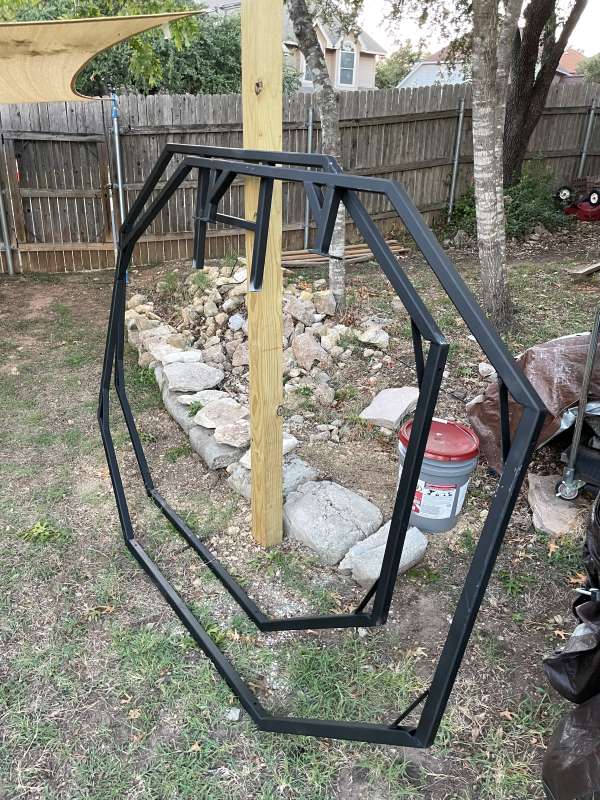 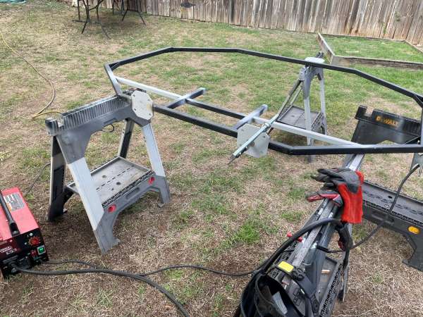 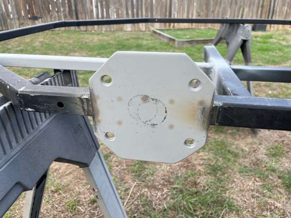 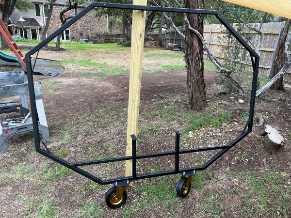 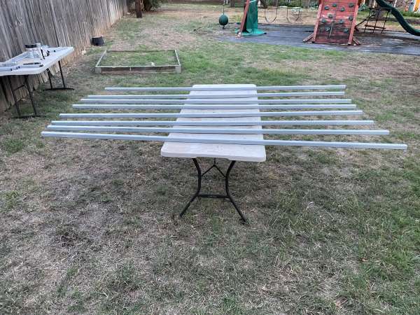 These final photos show the car being mounted to each hoop and later secured with the 8 support bars. All that is left is to remove the remainder of the rear suspension so the car can be rotated. This entire process took me 3 days and cost less than $450. IMO, this is not a very difficult job to do. You just need a welder, a drill, and something that can cut metal. 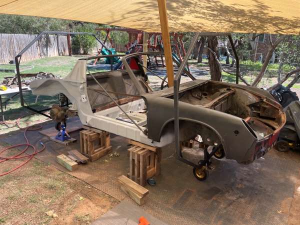 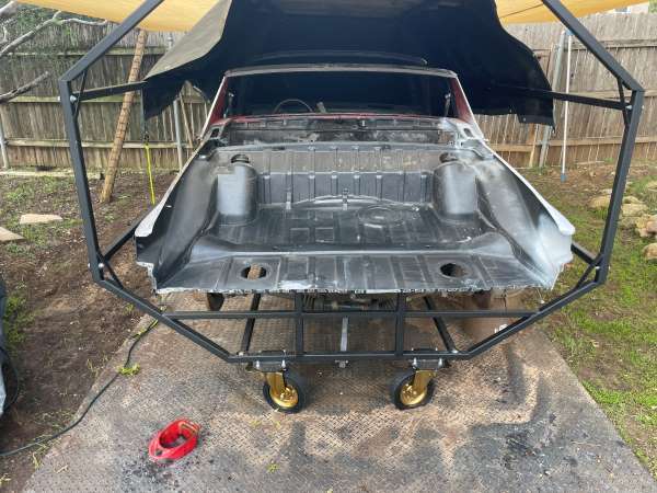 |
|
|
|
| friethmiller |
Dec 24 2023, 10:24 PM
Post
#76
|
|
Senior Member Group: Members Posts: 1,358 Joined: 10-February 19 From: Austin, TX Member No.: 22,863 Region Association: Southwest Region |
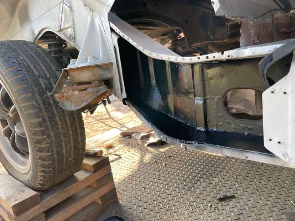
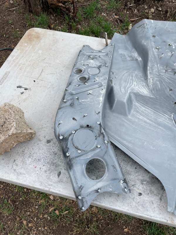
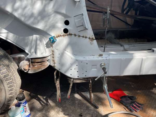
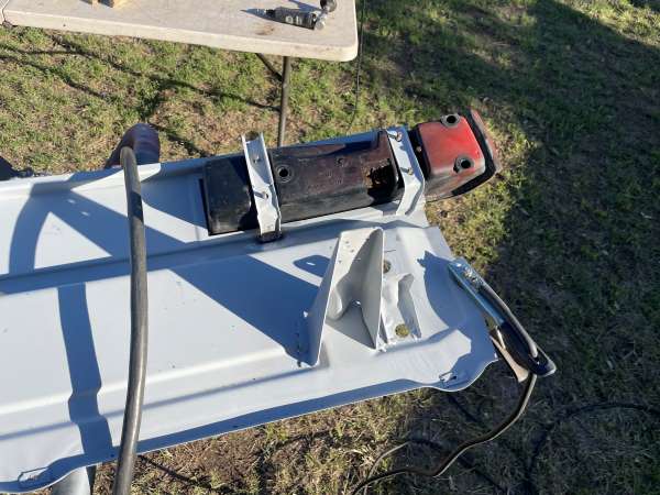
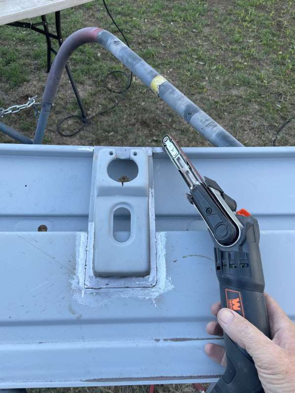
Back Panel Install (11/2023): Even though the car was now on the new rotisserie, I still wanted to take the time to weld in the new back panel. This part, like most of others, comes from Restoration Design. The original back panel was pretty much gone with a lot of rust, dents and cuts from the previous owner's attempt to remove the original lower trunk pan. I first cleaned and then hand sanded the part. After another cleaning, I gave the panel 2 thin coats of weld-thru primer. Unlike others, this part requires a lot of prep work prior to install. I had to transfer several items like the tow hook retention component, tail light retainers, trunk support hinges, speed nuts, etc. I decided to purchase a second-hand trunk lock support piece from a '75. It was pretty cheap and in a lot better shape than the one on my car. Note the use of the electric finger sander around the lock support piece. It really is a great tool for this sort of stuff.
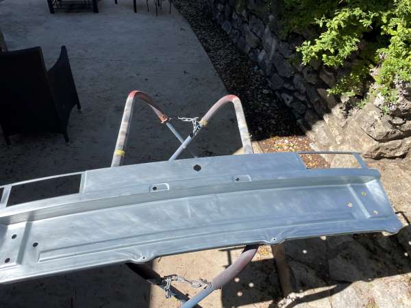    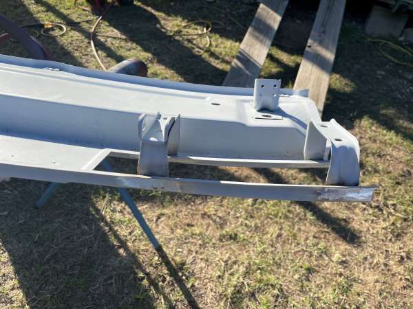 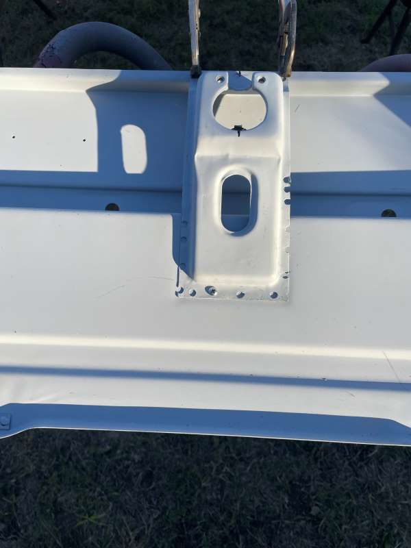 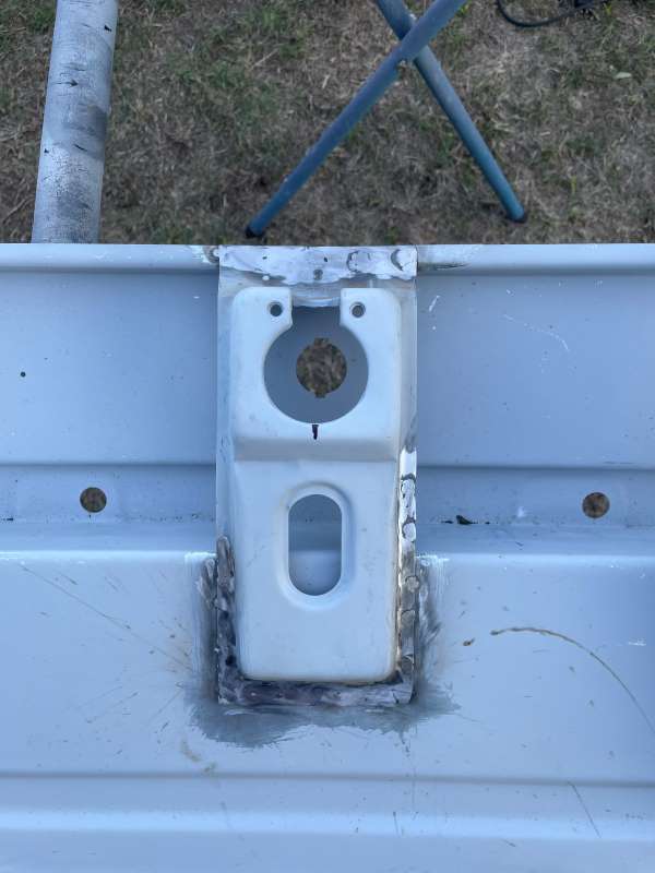  The following photos show the panel ready to be welded to the car. Also, a photo that demonstrates some of the metal prep involved on the car as well as the part being welded into the fender ends and trunk. Note: there are several welds below the trunk that put the rotisserie to its first use. 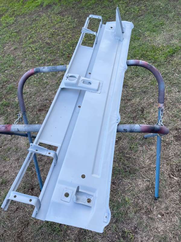 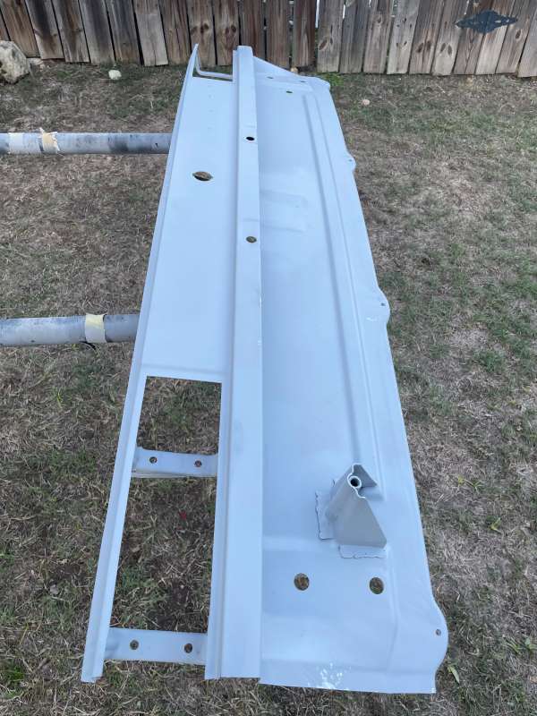 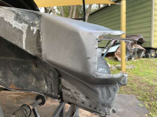 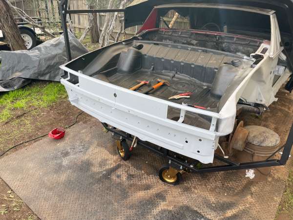 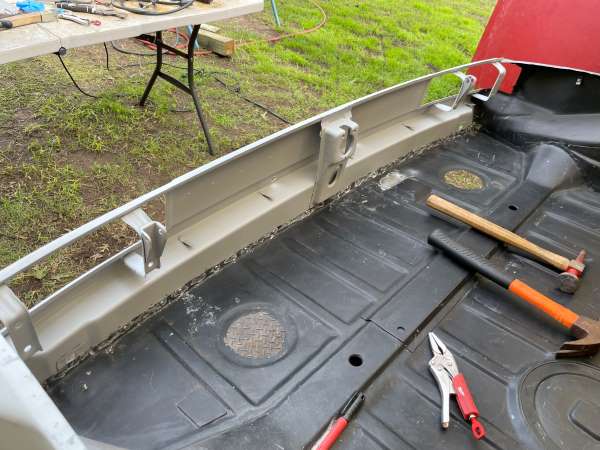 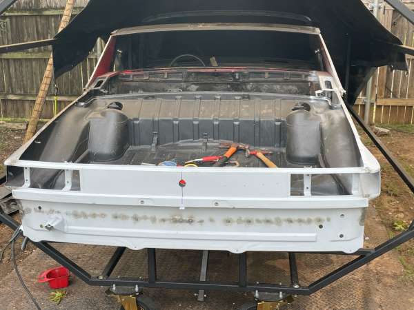 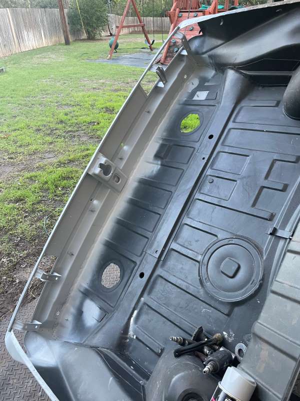 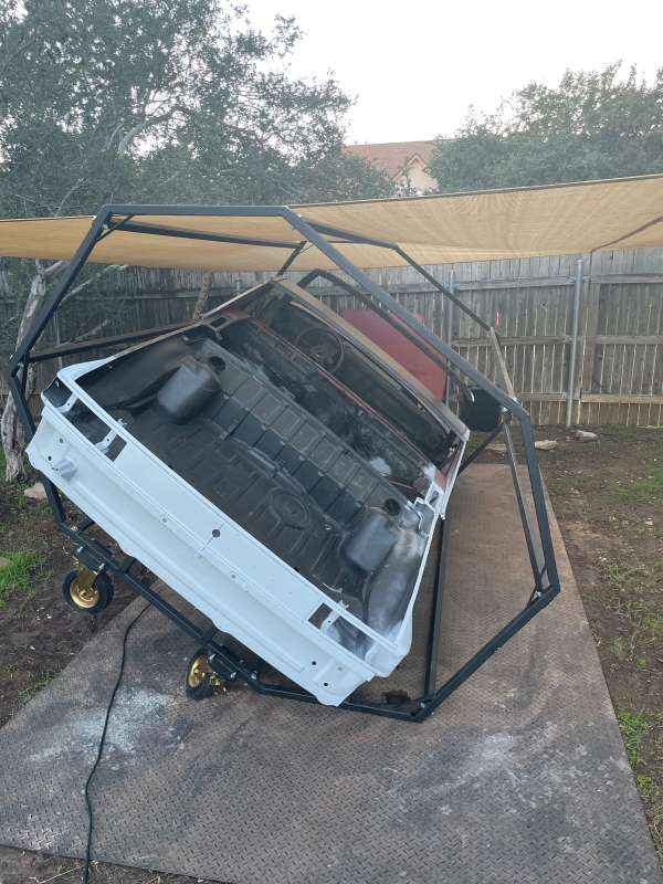 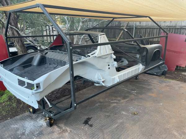 |
|
|
|
| wonkipop |
Dec 24 2023, 11:17 PM
Post
#77
|
|
914 Guru Group: Members Posts: 5,579 Joined: 6-May 20 From: north antarctica Member No.: 24,231 Region Association: NineFourteenerVille |
this thread is great.
my old dad (who has left the world) would love to meet you. he was a boilermaker. had all the welding tickets. used to call my mothers beetle, "hitler's revenge". whats remarkable about these photos is seeing just what a bad call f piech made when he put the battery where he decreed (demanded as per hitler type logic) it had to be. keep up the efforts. (IMG:style_emoticons/default/beerchug.gif) |
|
|
|
| friethmiller |
Dec 25 2023, 10:12 AM
Post
#78
|
|
Senior Member Group: Members Posts: 1,358 Joined: 10-February 19 From: Austin, TX Member No.: 22,863 Region Association: Southwest Region |
QUOTE(wonkipop @ Dec 24 2023, 11:17 PM) this thread is great. my old dad (who has left the world) would love to meet you. he was a boilermaker. had all the welding tickets. used to call my mothers beetle, "hitler's revenge". whats remarkable about these photos is seeing just what a bad call f piech made when he put the battery where he decreed (demanded as per hitler type logic) it had to be. keep up the efforts. (IMG:style_emoticons/default/beerchug.gif) Glad you like it! Wish I could have met your dad. He sounds a lot like mine, actually. FYI, I’ll have a few more progress posts in a couple of days. |
|
|
|
| rick 918-S |
Dec 25 2023, 01:31 PM
Post
#79
|
|
Hey nice rack! -Celette Group: Members Posts: 21,296 Joined: 30-December 02 From: Now in Superior WI Member No.: 43 Region Association: Northstar Region |
Man you In deep! Nice progress.
|
 |
|
| friethmiller |
Dec 28 2023, 08:27 AM
Post
#80
|
|
Senior Member Group: Members Posts: 1,358 Joined: 10-February 19 From: Austin, TX Member No.: 22,863 Region Association: Southwest Region |
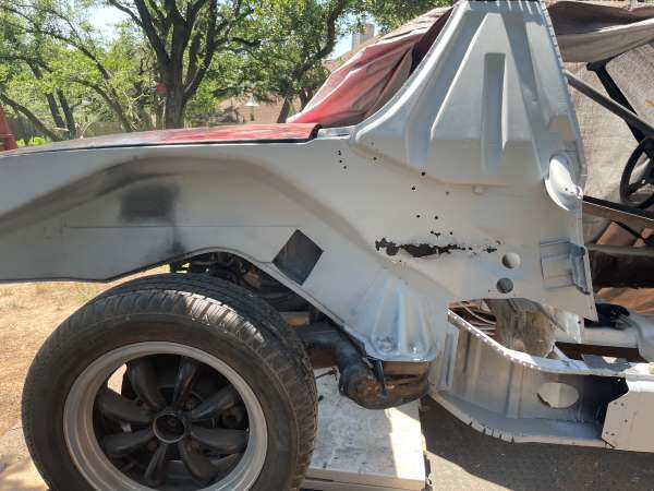
Passenger Inner Suspension Console Replacement - Part 1 (11/2023): With the back panel welded in on the trunk, it's finally time to replace the passenger side suspension console. I started by making a single cut to each gusset along the pinch weld seam. By doing this I can focus on removing just the inner console. I will reweld the gusset together at the end. Note the rust damage to the part.
  Before moving forward I cannot forget to weld in something that will facilitate the realignment of new part. I accomplished this by using 3 pieces of angle iron securely welded to the body of the car. You can see the metal piece is tangent to the face of the console ear with a hole drilled through to allow the bolt to be aligned to the console. This is obviously a very important step. Note the cuts made to the gusset to begin the process of removal. 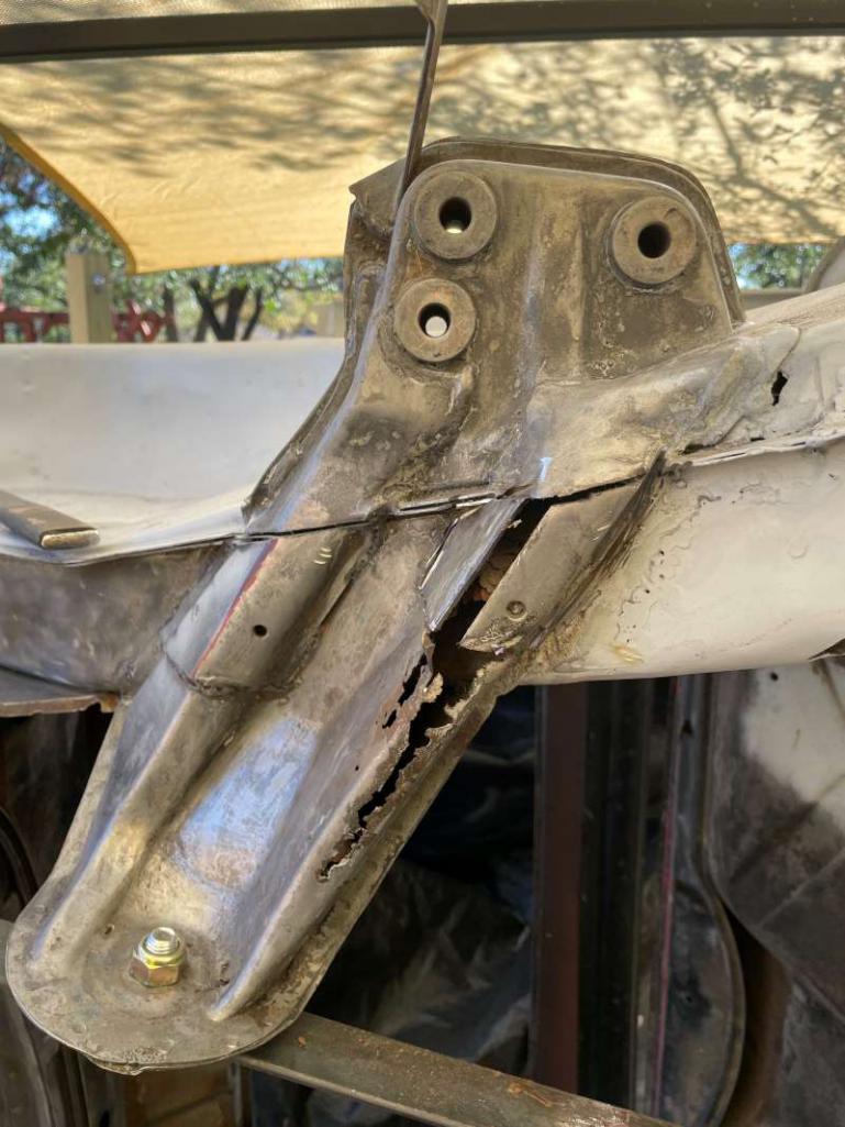 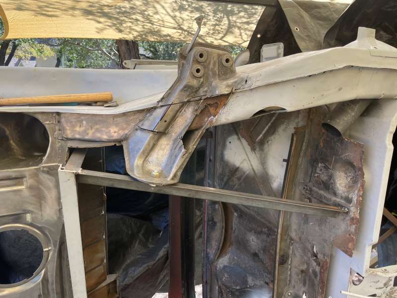 With the internals more exposed, you can begin to see that a mouse has lived here. Good grief! Having a water trapping nest only promotes the rust. With the bottom section of the console removed, I cut the rusted metal from the support rail skin for replacement. 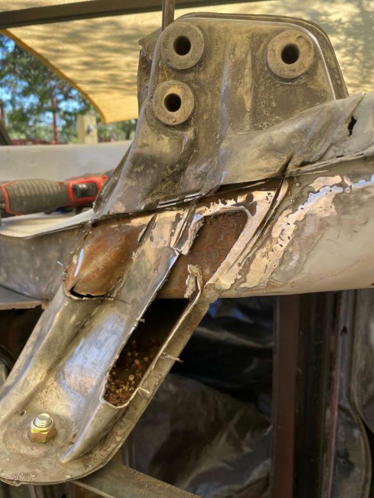 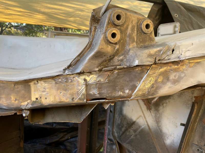 Like before, I used construction paper to develop the template which was cut from 18 gauge sheet metal. The following photo show this process. Note the one rosette weld that looks funny. This is what happens when you break for lunch and forget to turn the gas back on the welder (IMG:style_emoticons/default/051103-stupid4.gif) 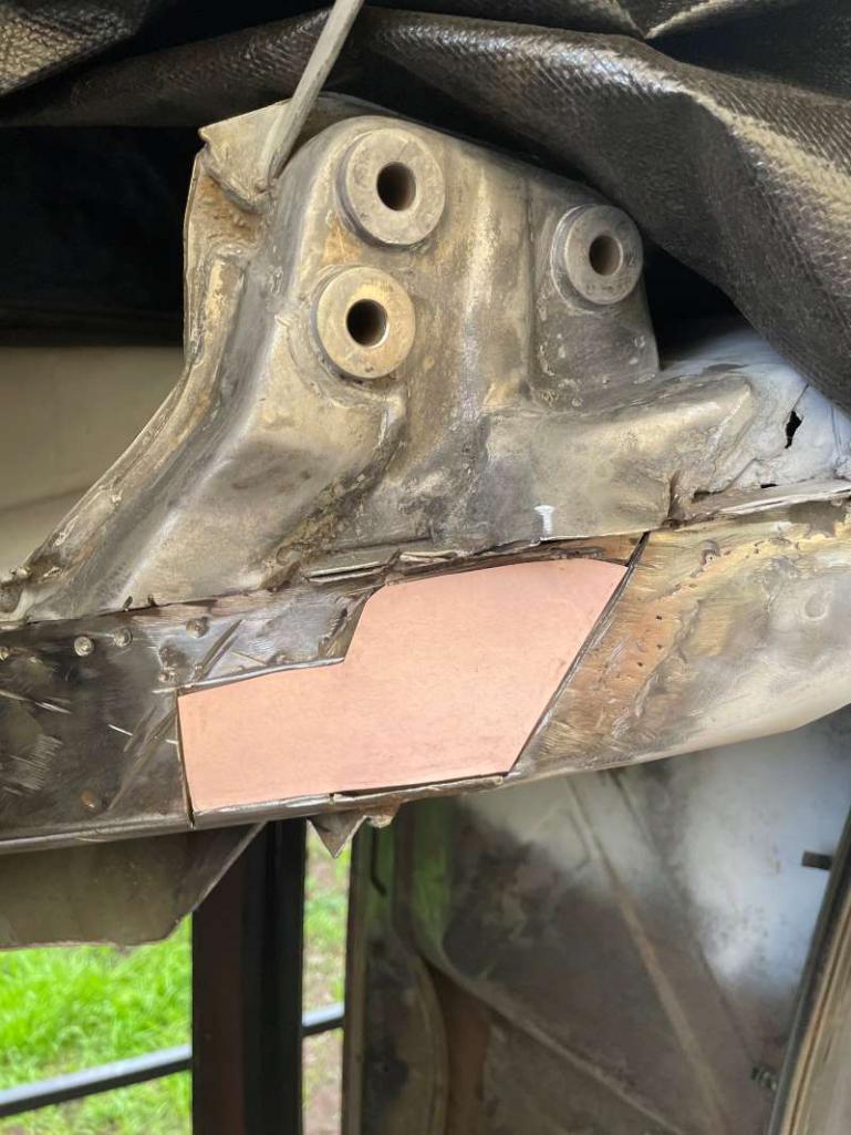 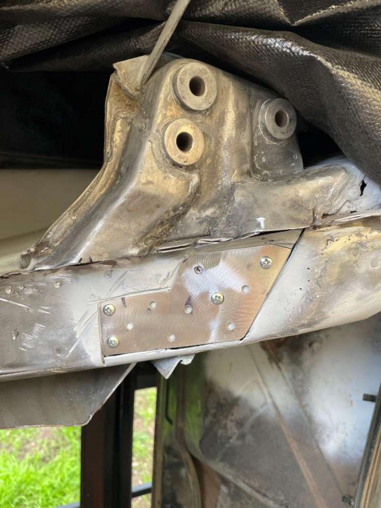 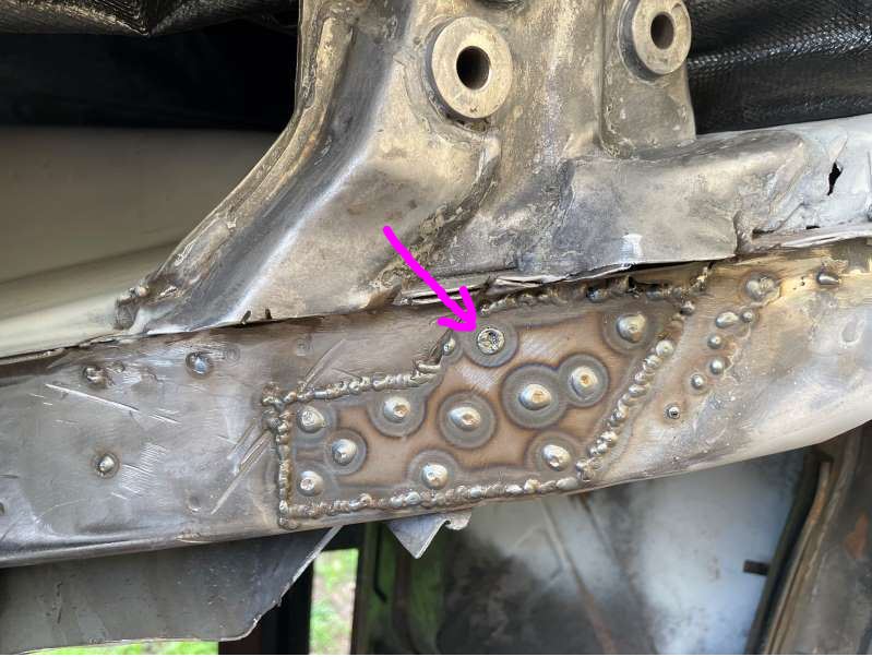 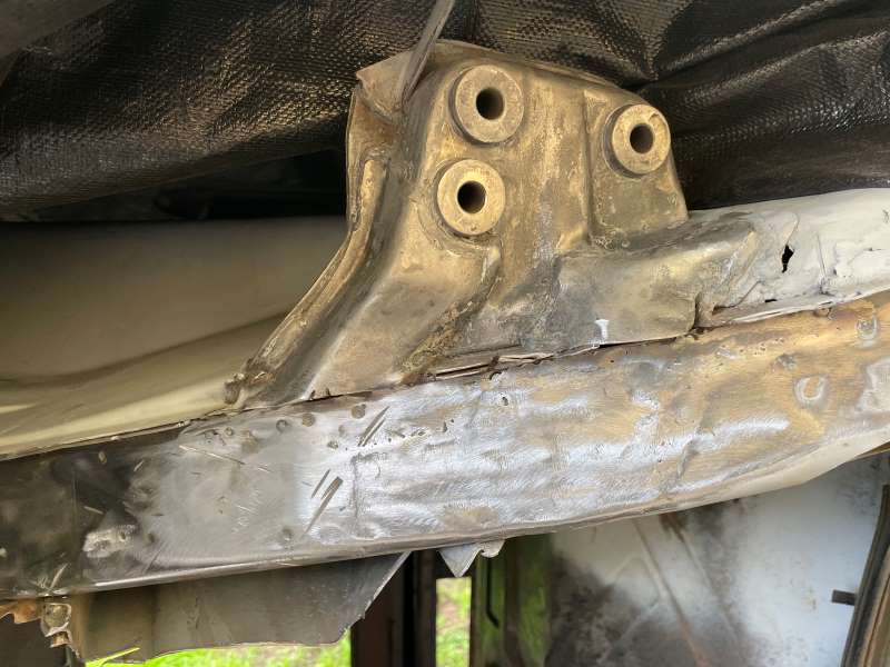 |
|
|
|
|
3 User(s) are reading this topic (3 Guests and 0 Anonymous Users)
0 Members:

|
Lo-Fi Version | Time is now: 4th July 2026 - 02:53 AM |
Invision Power Board
v9.1.4 © 2026 IPS, Inc.