|
|
|
Porsche, and the Porsche crest are registered trademarks of Dr. Ing. h.c. F. Porsche AG.
This site is not affiliated with Porsche in any way. Its only purpose is to provide an online forum for car enthusiasts. All other trademarks are property of their respective owners. |
|
|

  |

| StarBear |
 May 16 2025, 06:53 AM May 16 2025, 06:53 AM
Post
#21
|
|
Advanced Member  Group: Members Posts: 2,262 Joined: 2-September 09 From: NJ Member No.: 10,753 Region Association: North East States |
(IMG:style_emoticons/default/popcorn[1].gif) Enjoying this immensely.
Disconnected mine about 40 years ago but checked it out last year - still works fine. May just reconnect it for the heck of it. |
   |

 
|
| flipb |
May 16 2025, 07:08 AM
Post
#22
|
|
Senior Member Group: Members Posts: 1,873 Joined: 2-September 09 From: Fairfax, VA Member No.: 10,752 Region Association: MidAtlantic Region |
Just checked my 1974 manual and it's pretty much the same as pictured above. The seat belt interlock was still functional when I bought the car in 2009 and I was STUNNED that the passenger seat pressure sensor functioned as designed. Seemed remarkable for 70's tech like that to still be working 35 years later.
I later rewired to eliminate the interlock -- partly because it was annoying, but also to make way for installing modern seat belts. |
|
|
|
| friethmiller |
May 16 2025, 07:30 AM
Post
#23
|
|
Senior Member Group: Members Posts: 1,221 Joined: 10-February 19 From: Austin, TX Member No.: 22,863 Region Association: Southwest Region |
Great thread, Phil. (IMG:style_emoticons/default/popcorn[1].gif) On my red '74 I rewired everything based on the following diagram (Jeff's?). I never plugged any of the "relays" in to even test it out. I wonder if it would work? This thread has me thinking. I know the passenger seat has the wiring (IMG:style_emoticons/default/idea.gif)
I know I have the smaller relay (see arrow). Not sure about the big one. I remember it being pretty bad inside. 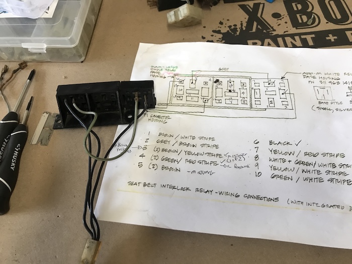  |
 |
|
| ClayPerrine |
May 16 2025, 09:16 AM
Post
#24
|
|
Life's been good to me so far..... Group: Admin Posts: 16,542 Joined: 11-September 03 From: Hurst, TX. Member No.: 1,143 Region Association: NineFourteenerVille |
I can remember taking the seat cushion out of Betty's 74 years ago before I ripped out all that junk. It was at my parent's house, and my nephew was there talking to me. He asked about the wire coming out of the seat cushion. With a straight face, I told him "That is the sensor for the ejector seat. If I don't like someone, I can eject them from the car. This keeps it from going off if no one is in the seat." The look on his face was priceless. And when Betty offered him a ride he quickly refused.
(IMG:style_emoticons/default/happy11.gif) This is the same kid that, at about 13 years old, was playing with my spark plug boot puller tool. It kinda looks like this: 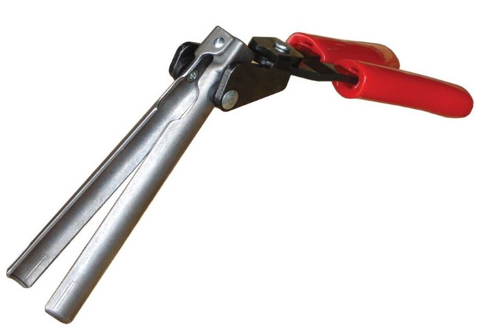 He was holding it, clacking the ends together when he asked me "What is this thing?" I said "It's a penis stretcher. Do you need to borrow it?" He dropped it like it was red hot. That same kid now has a master's degree in engineering and works for Peterbilt, so I don't think I did him any harm. (IMG:style_emoticons/default/happy11.gif) |
|
|
|
| Superhawk996 |
May 16 2025, 12:54 PM
Post
#25
|
|
914 Guru Group: Members Posts: 7,774 Joined: 25-August 18 From: Woods of N. Idaho Member No.: 22,428 Region Association: Galt's Gulch |
QUOTE(friethmiller @ May 16 2025, 09:30 AM)  I know I have the smaller relay (see arrow). Not sure about the big one. I remember it being pretty bad inside. (IMG:style_emoticons/default/biggrin.gif) good catch! Jeff has shared that wiring info and small conventional cube relay with me. We haven’t quite figured out how what plays into this - the cube relay appears to be undocumented in any of the Haynes or factory wiring diagrams I’m sure I’ll be asking for help from some folks to verify wiring on that - my car is a 73’. I’ve decided to ignore the cube relay in the short term and just document the interlock relay 1st. Once that is documented - then I think we can better figure out what the cube relay is doing. |
|
|
|
| Superhawk996 |
May 16 2025, 12:56 PM
Post
#26
|
|
914 Guru Group: Members Posts: 7,774 Joined: 25-August 18 From: Woods of N. Idaho Member No.: 22,428 Region Association: Galt's Gulch |
QUOTE(ClayPerrine @ May 16 2025, 11:16 AM) I can remember taking the seat cushion out of Betty's 74 years ago before I ripped out all that junk. It was at my parent's house, and my nephew was there talking to me. He asked about the wire coming out of the seat cushion. With a straight face, I told him "That is the sensor for the ejector seat. If I don't like someone, I can eject them from the car. This keeps it from going off if no one is in the seat." The look on his face was priceless. And when Betty offered him a ride he quickly refused. (IMG:style_emoticons/default/happy11.gif) This is the same kid that, at about 13 years old, was playing with my spark plug boot puller tool. It kinda looks like this: He was holding it, clacking the ends together when he asked me "What is this thing?" I said "It's a penis stretcher. Do you need to borrow it?" He dropped it like it was red hot. That same kid now has a master's degree in engineering and works for Peterbilt, so I don't think I did him any harm. (IMG:style_emoticons/default/happy11.gif) (IMG:style_emoticons/default/pray.gif) (IMG:style_emoticons/default/av-943.gif) |
|
|
|
| barefoot |
May 16 2025, 01:29 PM
Post
#27
|
|
Senior Member Group: Members Posts: 1,490 Joined: 19-March 13 From: Charleston SC Member No.: 15,673 Region Association: South East States |
QUOTE(Superhawk996 @ May 16 2025, 02:54 PM) QUOTE(friethmiller @ May 16 2025, 09:30 AM) I know I have the smaller relay (see arrow). Not sure about the big one. I remember it being pretty bad inside. (IMG:style_emoticons/default/biggrin.gif) good catch! Jeff has shared that wiring info and small conventional cube relay with me. We haven’t quite figured out how what plays into this - the cube relay appears to be undocumented in any of the Haynes or factory wiring diagrams I’m sure I’ll be asking for help from some folks to verify wiring on that - my car is a 73’. I’ve decided to ignore the cube relay in the short term and just document the interlock relay 1st. Once that is documented - then I think we can better figure out what the cube relay is doing. I’ve got to apologize in advance - have some commitments with the wife that I have to take care of during the day - will try to post the cushion and belt latch info later tonight You must have a lot of free time on your hands, is this a retirement project ? (IMG:style_emoticons/default/stirthepot.gif) A lot of work for a tiny return to the 914 community. Barefoot |
|
|
|
| Superhawk996 |
May 16 2025, 02:00 PM
Post
#28
|
|
914 Guru Group: Members Posts: 7,774 Joined: 25-August 18 From: Woods of N. Idaho Member No.: 22,428 Region Association: Galt's Gulch |
QUOTE(barefoot @ May 16 2025, 03:29 PM) You must have a lot of free time on your hands, is this a retirement project ? (IMG:style_emoticons/default/stirthepot.gif) A lot of work for a tiny return to the 914 community. Barefoot Yup. Personal enrichment - want to understand it and how it works. I mentioned I had character flaws right up front (IMG:style_emoticons/default/happy11.gif) Stated as a challenge from another member that shares a hatred of the buzzer but doesn’t want to disable and bypass the Fasten Seat Belt light functionality completely. |
|
|
|
| ClayPerrine |
May 16 2025, 02:49 PM
Post
#29
|
|
Life's been good to me so far..... Group: Admin Posts: 16,542 Joined: 11-September 03 From: Hurst, TX. Member No.: 1,143 Region Association: NineFourteenerVille |
QUOTE(Superhawk996 @ May 16 2025, 03:00 PM) QUOTE(barefoot @ May 16 2025, 03:29 PM) You must have a lot of free time on your hands, is this a retirement project ? (IMG:style_emoticons/default/stirthepot.gif) A lot of work for a tiny return to the 914 community. Barefoot Yup. Personal enrichment - want to understand it and how it works. I mentioned I had character flaws right up front (IMG:style_emoticons/default/happy11.gif) Stated as a challenge from another member that shares a hatred of the buzzer but doesn’t want to disable and bypass the Fasten Seat Belt light functionality completely. I would just build a small electronic circuit with a 555 timer that would turn the light on when the ignition was switched on, and shut of 15 seconds later. Then wire it to the back of the light. (IMG:http://www.914world.com/bbs2/uploads_offsite/www.circuits-diy.com-1143-1747428580.1.png) Replace the resistor and the buzzer with the fasten seat belt light. Instead of the push button switch, wire it to fuse 9 on the fuse box. Now the light comes on, but no buzzer and no failed starts due to the interlock relay. |
|
|
|
| davep |
May 16 2025, 03:18 PM
Post
#30
|
|
914 Historian Group: Benefactors Posts: 5,361 Joined: 13-October 03 From: Burford, ON, N0E 1A0 Member No.: 1,244 Region Association: Canada |
Just saw this thread. I worked on this about 3 years ago. There appears to be about 4 circuits: 2 x 74, 1x 75 1 x 76
1974 there is a ground terminal (1/4" spade) riveted to the floor pan, and is either used or not. This uses the two relay system. 1975 uses just the dual relay 1976 uses just a single relay The two minute restart delay comes from the oil pressure switch, and the time that it takes for the oil pressure to drop, the switch closes, and the idiot light comes on. SO, if you want to thwart the interlock system, then just pull the oil pressure switch wires from the relay and join them together so that the idiot light works as usual. Then the logic relay is tricked into thinking the oil pressure is always high. I have some better drawings if you need them. |
|
|
|
| Superhawk996 |
May 16 2025, 05:31 PM
Post
#31
|
|
914 Guru Group: Members Posts: 7,774 Joined: 25-August 18 From: Woods of N. Idaho Member No.: 22,428 Region Association: Galt's Gulch |
QUOTE(davep @ May 16 2025, 05:18 PM) The two minute restart delay comes from the oil pressure switch, and the time that it takes for the oil pressure to drop, the switch closes, and the idiot light comes on. I have some better drawings if you need them. @davep glad to hear that about the oil pressure input onto pin “B” - that was the only way I can see the time dependency being met based on the bench testing. I was thinking that but didn’t quite want to say that out loud just yet. 2 minutes +/- 1 minutes is pretty ambitious for oil pressure bleed down. May just have been my cars. While I can see 1 minute being pretty reasonable I’m not sure any of my cars held oil pressure switch off for 3 minutes after a shutdown when hot. By all means if you have info to add about year to year dependency - post it up. Since I have never owned anything other than 73’s I’m at a disadvantage on this little journey. |
|
|
|
| Superhawk996 |
May 16 2025, 05:37 PM
Post
#32
|
|
914 Guru Group: Members Posts: 7,774 Joined: 25-August 18 From: Woods of N. Idaho Member No.: 22,428 Region Association: Galt's Gulch |
QUOTE(ClayPerrine @ May 16 2025, 04:49 PM) I would just build a small electronic circuit with a 555 timer that would turn the light on when the ignition was switched on, and shut of 15 seconds later. You did catch the part about my personality flaws right? Ultimately I want to get to a complete schematic of the interlock relay and want to be able to model it in LTspice Getting a bit ahead of myself but enjoy! 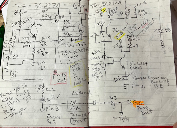 Why do it the easy way? Someone needs to document this thing. This whole 70s era Rube Goldberg contraption could be replaced in about an hour with an Arduino - where’s the challenge in that? (IMG:style_emoticons/default/av-943.gif) |
|
|
|
| Superhawk996 |
May 16 2025, 07:22 PM
Post
#33
|
|
914 Guru Group: Members Posts: 7,774 Joined: 25-August 18 From: Woods of N. Idaho Member No.: 22,428 Region Association: Galt's Gulch |
Driver side seat circuits
The driver side seat cushion and belt inputs are: SF - driver side seat cushion (NO) GF - driver side seat belt latch switch (NC) NO = Normally open switch contacts NC = Normally closed switch contacts If we look at the schematic we can see that the ground first has to travel through the seat cushion switch. If someone is sitting in the seat, the ground signal then travels over to the seat belt latch / receiver switch. Since the belt receiver switch is a normally closed switch, the ground then travels through the switch to the interlock relay if the seat belt isn’t fastened. With a ground on input GF - the interlock relay lights the FSB light and the buzzer activates. 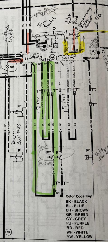 If no one is sitting in the vehicle - the ground never makes it to the interlock relay. Similarly, if the seatbelt is fastened the normally closed receiver switch is opened and the ground cannot make it to the interlock relay and the FSB light and buzzer will be off. This allows the vehicle to be started from outside the vehicle by leaning over the door. Obviously before days of clutch interlock and such. (IMG:style_emoticons/default/biggrin.gif) People were assumed to be a lot smarter back in those less litigious days The photo below shows the driver side pins circled in red. The passenger side seat cushion and belt inputs are circled in blue. 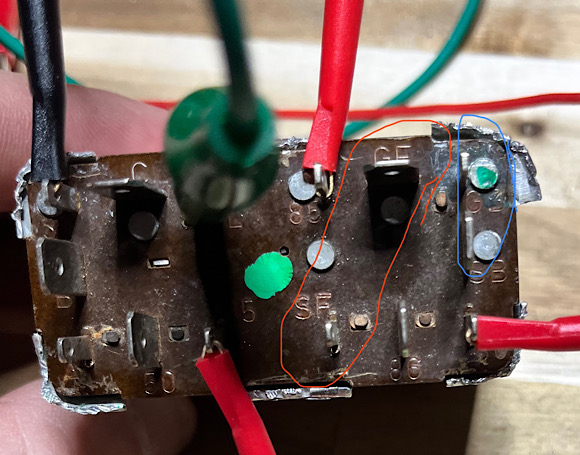 The passenger side inputs work exactly the same as the driver side. |
|
|
|
| Superhawk996 |
May 16 2025, 07:32 PM
Post
#34
|
|
914 Guru Group: Members Posts: 7,774 Joined: 25-August 18 From: Woods of N. Idaho Member No.: 22,428 Region Association: Galt's Gulch |
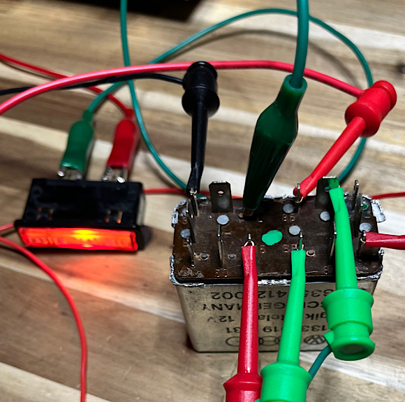
Here’s how the situation looks on the bench with the situation of the seat belt cushion occupied and the seat belt unfastened.
 |
|
|
|
| Superhawk996 |
May 16 2025, 07:34 PM
Post
#35
|
|
914 Guru Group: Members Posts: 7,774 Joined: 25-August 18 From: Woods of N. Idaho Member No.: 22,428 Region Association: Galt's Gulch |
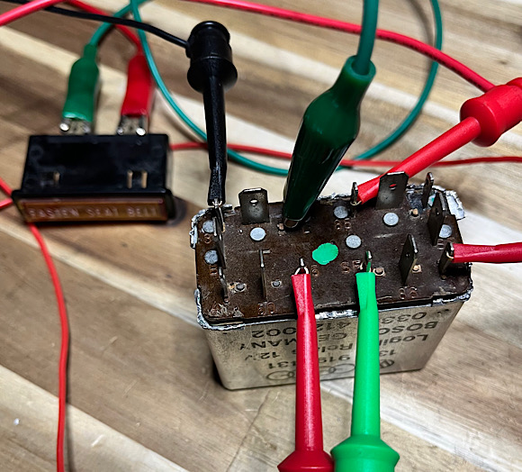
And again with the seat belt fastened where the open switch in the seat belt receiver isn’t letting the ground pass to the interlock
 |
|
|
|
| Superhawk996 |
May 16 2025, 08:06 PM
Post
#36
|
|
914 Guru Group: Members Posts: 7,774 Joined: 25-August 18 From: Woods of N. Idaho Member No.: 22,428 Region Association: Galt's Gulch |
So at this point we are though the sit down & buckle up portion of the “logic” sequence needed to start.
The next thing to do is to apply 12v power to pin C (circled in orange) - in the subsequent photo this will be a yellow wire with +12v on it coming into pin C. 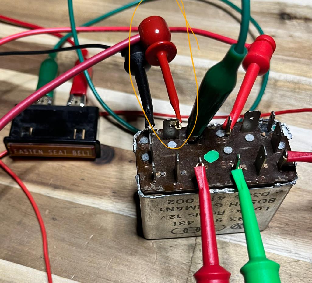 This is the same as turning the key to the start position The result is a click as the starter interlock relay energizes To show that the starter interlock solenoid has closed and connected pin C to pin 50 I’ve rigged up a lamp with the yellow wire on pin 50 and the other side of the lamp to ground. This current path is what the yellow starter solenoid wire will flow through in vehicle. 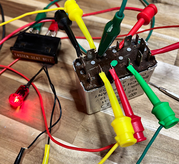 I’ll attach a video here a little later to show this sequence of events and so you can hear the starter solenoid interlock relay pull in. https://www.youtube.com/watch?v=KFhefyS-sgc?si=7lUXcryHdgSQZV7Z Note: @sirandy - something squirrelly going on where pictures between post 36 & 37 are somehow inter related - editing in one post screws up photos in the other ?? Never seen this before. Sort of seems the photos for post 36 are resident in post 37. |
|
|
|
| Superhawk996 |
May 16 2025, 08:26 PM
Post
#37
|
|
914 Guru Group: Members Posts: 7,774 Joined: 25-August 18 From: Woods of N. Idaho Member No.: 22,428 Region Association: Galt's Gulch |
I know almost no one cares about the internal details but tough luck - I do so skip the nerd stuff if you don’t care.
I don’t know exactly what I was expecting to happen when the seat belt and cushions conditions were met but I was greeted with nothing. No activation of the starter solenoid relay . . . Nothing just silence. For some reason I was sort of expecting that relay to pull in on its own but it didn’t. Wanting to know more about how this black box works - I started digging into and documenting the circuits within the black box. What I found was that the starter interlock solenoid needs to have 12v on pin C in order for the relay to actuate. This is because Pin C is attached to the solenoid coil on one side. The other ground side is supplied inside the black box by a transistor (T9) that is turned on allowing a path to ground for the other side of the solenoid coil. Of course this transistor is only turned on when the seat belt has been fastened. Here’s my crude notes for those that are really interested in the gory details. Part of my goal here was to be able to troubleshoot and repair a defective interlock relay (more on that later). In hindsight the fact that the solenoid needs 12v on pin C makes sense. It wouldn’t make sense to keep the solenoid relay within the interlock relay energized all the time. This way it only temporarily energizes when the key is actually in the Start position. I’m also a little surprised by how little the relay is considering that the actual starter solenoid in the stater motor pulls about 25 amps through this interlock relay. Strangely - not one of the three interlock relays I have looks the least bit worn or burned though. It certainly worked when these cars were new. I sort of suspect that many of these interlocks got removed over the years simply because they are a black box and it’s not intuitive to understand what’s going on in that little silver box. So if someone was having starting issues for other reasons (bad ground strap for example) it would be easy to see how pins C and pin 50 got a jumper - end of story. Don’t get me wrong - I don’t think this is a good design. To me it’s just an interesting time capsule of 70s vintage electronics and VW / Porsche trying to meet the mandates imposed by new FMVSS regulations. |
|
|
|
| Superhawk996 |
May 16 2025, 09:03 PM
Post
#38
|
|
914 Guru Group: Members Posts: 7,774 Joined: 25-August 18 From: Woods of N. Idaho Member No.: 22,428 Region Association: Galt's Gulch |
Oh - here’s which relays are which
The starter interlock relay is on the left in green The buzzer “relay” is on the right in red 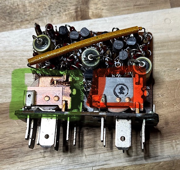 The buzzer is actually just a simple relay wired such that when the solenoid coil is energized and pulls in - it disconnects the coil via the relay contacts. The coil de-energizes and the relay returns, the solenoid coil is again energized, etc. The energize / de-energize cycle happens so quickly you get a buzz. On the top of the relay contacts there is a thin metal resonator with the “44” stamp that resonates that shrill tone that is heard as the buzzer. |
|
|
|
| Superhawk996 |
May 16 2025, 09:07 PM
Post
#39
|
|
914 Guru Group: Members Posts: 7,774 Joined: 25-August 18 From: Woods of N. Idaho Member No.: 22,428 Region Association: Galt's Gulch |
More coming on observed anomalies and how the oil pressure switch and park brake modify the light strategy.
Here’s the overview of how Transistor T9 controls the Starter interlock this is missing from the previous post #37 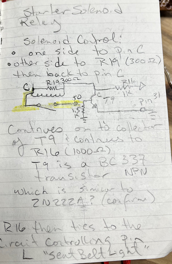 |
|
|
|
| Superhawk996 |
May 19 2025, 11:44 AM
Post
#40
|
|
914 Guru Group: Members Posts: 7,774 Joined: 25-August 18 From: Woods of N. Idaho Member No.: 22,428 Region Association: Galt's Gulch |
This video shows behavior of the relay under a couple conditions
Starts with power being switched on as if someone is sitting in driver seat - unbelted Seat belt is then Fastened (removal of switched ground from pin GF) Then Key turned to start (yellow +12v applied to pin C) which is shown by the lamp between pin C and pin 50 lighting - as if the starter was now being allowed to crank the engine. So that is the basic start sequence After that the video proceeds with unfastening the seat belt (switched ground added back to pin GF) After that we see that adding a switched ground to pin A - simulates applying the park brake. Ground on pin A = silence the lamp and buzzer Then the switched ground is moved over to pin B. Pin B represents having oil pressure . As DaveP correctly stated earlier if the relay thinks the engine is running - or still has oil pressure while it bleeds down - the lights and buzzer are disabled and the vehicle should be able to be restarted. NOTE: this restart attempt is NOT shown in the video - doesn’t always work - I’ll come back to the later regarding anomalies I’ve seen when testing this relay After moving the switched ground back to pin A (park brake applied) and the seat belt unfastened - 12v is again applied to pin C, we see the FSB lamp lights and the buzzer comes on but the starter interlock isn’t enabled - basically reminding the occupant to fasten the seat belt before the engine can be started The seat belt is then fastened (switched ground removed from pin GF) and 12v is applied to pin C and we can see the vehicle would be allowed to start https://www.youtube.com/watch?v=qo55bVLfsYM?si=ZCez5BhdQteaLknO |
|
|
|
|
1 User(s) are reading this topic (1 Guests and 0 Anonymous Users)
0 Members:

|
Lo-Fi Version | Time is now: 10th April 2026 - 03:10 AM |
Invision Power Board
v9.1.4 © 2026 IPS, Inc.