|
|
|
Porsche, and the Porsche crest are registered trademarks of Dr. Ing. h.c. F. Porsche AG.
This site is not affiliated with Porsche in any way. Its only purpose is to provide an online forum for car enthusiasts. All other trademarks are property of their respective owners. |
|
|

  |

| Chad911sc |
 Nov 21 2025, 01:23 PM Nov 21 2025, 01:23 PM
Post
#1
|
|
Member  Group: Members Posts: 225 Joined: 24-September 24 From: Florida Member No.: 28,374 Region Association: South East States |
So I got my crank back from a different machine shop this time, and they turned it down .010 on the mains to clean up my out of roundness. I rotated it several rotations on an V-block and had no deviation. My new oversized bearing came in yesterday, and I’m checking clearances now. I plastigauged the middle bearing and I have what looks to be .0018 of clearance. Is this acceptable? Here is the pics to double check me.
My rods were right at .001, so I’m good there. Attached thumbnail(s) 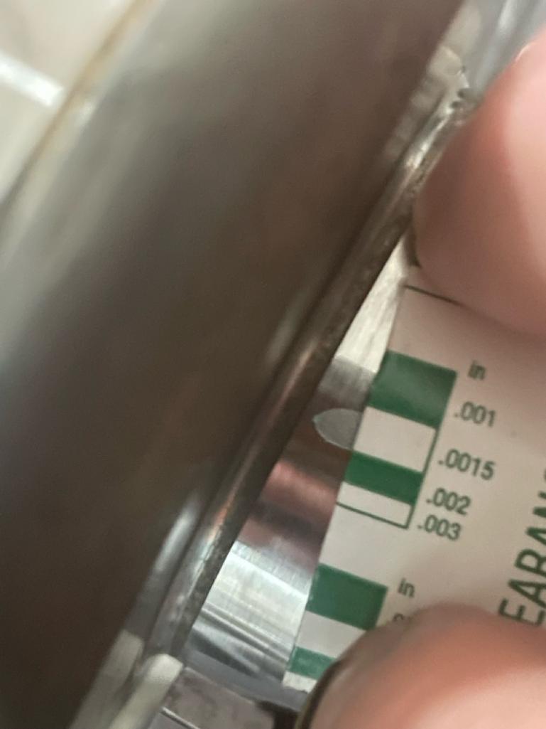 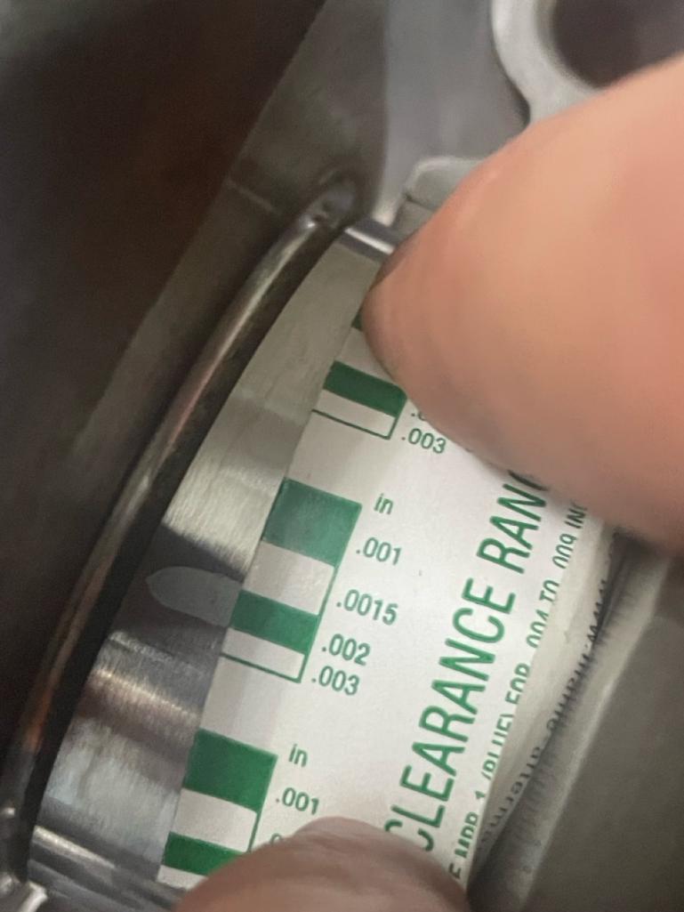
|
   |

 
|
| rfinegan |
Nov 21 2025, 01:56 PM
Post
#2
|
|
Senior Member Group: Members Posts: 1,137 Joined: 8-February 13 From: NC Member No.: 15,499 Region Association: MidAtlantic Region |
.001 feels a little tight to me on the rods. Careful
|
|
|
|
| mepstein |
Nov 21 2025, 02:00 PM
Post
#3
|
|
914-6 GT in waiting Group: Members Posts: 20,254 Joined: 19-September 09 From: Landenberg, PA/Wilmington, DE Member No.: 10,825 Region Association: MidAtlantic Region |
I would have the machine shop do the measurements. They have measuring tools that are much better than plastigauge.
You really want to measure at every bearing. Just measuring one and hoping the others are the same can get you in trouble. |
 |
|
| Chad911sc |
Nov 21 2025, 02:50 PM
Post
#4
|
|
Member Group: Members Posts: 225 Joined: 24-September 24 From: Florida Member No.: 28,374 Region Association: South East States |
@rfinegan
I didn’t have the rod journals turned, they were right on spec. The rods were bought new from LN engineering, and they prepped and sized them before shipping. The engine ran for around 3 hours the first time, and the bearings upon disassembly were fine. They were definitely reusable, but I bought new ones anyway. @mepstein The machine shop did mic each journal and they were all right on spec. I then rechecked them when I got home and obtained the same results. From what I’ve read, the clearance should be .002 on the middle bearing because it takes the load of 2 rods. Mine looks like it’s a hair tighter, so I was wanting to know if that is acceptable, or do I need to polish t a bit and try to get it right at .002 |
|
|
|
| Superhawk996 |
Nov 21 2025, 06:36 PM
Post
#5
|
|
914 Guru Group: Members Posts: 7,536 Joined: 25-August 18 From: Woods of N. Idaho Member No.: 22,428 Region Association: Galt's Gulch |
QUOTE(Chad911sc @ Nov 21 2025, 04:50 PM)  From what I’ve read, the clearance should be .002 on the middle bearing because it takes the load of 2 rods. Mine looks like it’s a hair tighter, so I was wanting to know if that is acceptable, or do I need to polish t a bit and try to get it right at .002 Take with grain of salt. Clearance advice is like oil - it’s sort of a religion. The advice is worth what you paid. Peter Russek repair guide lists crank main clearance for #1 & 3 as .002”-.004 #2 as 0.0011” - 0.0035” Personally I like .002” as the target. But trying to measure to ten thousandths with plasticgage is not realistic. As was stated previously, I put more faith in measuring OD with a micrometer and bearing bore ID (with case fully torqued) with a bore gauge and doing the math. I would base any next steps on assembled drag with only a light coat of 20wt oil and see how much drag is on the crank and then we are down to subjective feel. If you truly are at 0.0018” plan to run something lighter than the 20W-50 guys seem to love or you’ll be asking for problems IMHO. |
|
|
|
| 930cabman |
Nov 21 2025, 06:46 PM
Post
#6
|
|
Advanced Member Group: Members Posts: 4,334 Joined: 12-November 20 From: Buffalo Member No.: 24,877 Region Association: North East States |
I have always liked the "assembled drag" as Phil has mentioned. Unless one has the correct gaging tools there are variables. ie, checking the case for straightness and dimensions can only be accomplished with fancy tooling generally not available to many of us garage hacks. Checking a crank is more straightforward.
Hope it goes correct for you this time |
|
|
|
| Chad911sc |
Nov 22 2025, 06:32 AM
Post
#7
|
|
Member Group: Members Posts: 225 Joined: 24-September 24 From: Florida Member No.: 28,374 Region Association: South East States |
10-4
I will put the bearings in dry and torque the case down today and get my exact measurements on the bearings. I already have my exact measurements on the crank journals from the machine shop that I double checked at home with my mic and post those today. |
|
|
|
| Chad911sc |
Nov 22 2025, 12:54 PM
Post
#8
|
|
Member Group: Members Posts: 225 Joined: 24-September 24 From: Florida Member No.: 28,374 Region Association: South East States |
My readings came out with….
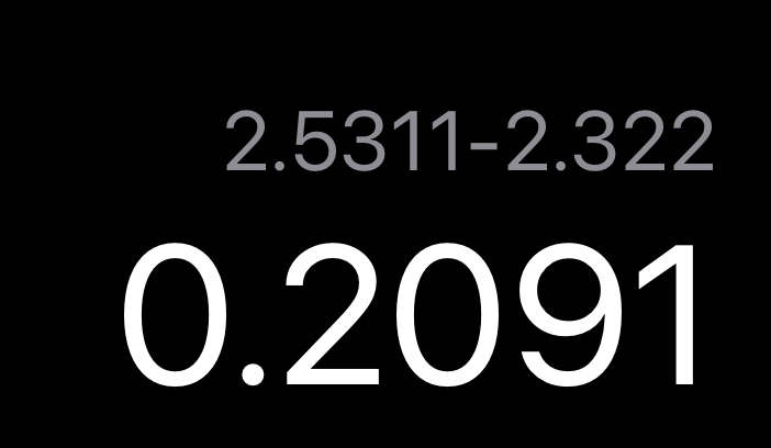
Journal 1) .002 clearance 2) .0017 3) .002 4) .003 So should I polish down the middle main until I reach .002? Or will it fly at that clearance? The plasti-gauge was actually right on the money. All the readings were done with bore gauge except the last one because my bore gauge was too large for it. It was done with snap gauge and micrometer. Attached thumbnail(s)   
|
|
|
|
| Superhawk996 |
Nov 22 2025, 01:41 PM
Post
#9
|
|
914 Guru Group: Members Posts: 7,536 Joined: 25-August 18 From: Woods of N. Idaho Member No.: 22,428 Region Association: Galt's Gulch |
QUOTE(Chad911sc @ Nov 22 2025, 02:54 PM) So should I polish down the middle main until I reach .002? Or will it fly at that clearance? I’m not trying to be a weasel but only you can answer that question. For better or worse, this is the dilemma of building engines yourself. A typical builder wouldn’t give a flip. A world class builder will sweat the details even if that meant scrapping a crank (not implying that is even relevant here). I will say I wouldn’t try to hand polish 0.0003”. Giving it back to a machine shop to polish 0.0003” is a craps shoot. You’ll find that you have at least +/- 0.0002” repeatability depending on who is manning the micrometer. Not to be overly critical but you also have some measurement error mismatch in that you are measuring the crank to tenthousandths but the bore ID is only measured to thousandths so you’re kidding yourself a little on measurement accuracy. (See below). As stated previously if it were me, I’d assemble with oil only (no assembly lube or grease) and then I’d have to subjectively evaluate. I feel your pain and fully understand the apprehension. I go through this on every engine build I’ve ever done. What is good enough and how much time and money to spend seeking perfection. |
|
|
|
| Superhawk996 |
Nov 22 2025, 01:55 PM
Post
#10
|
|
914 Guru Group: Members Posts: 7,536 Joined: 25-August 18 From: Woods of N. Idaho Member No.: 22,428 Region Association: Galt's Gulch |
I’m going to add one more thought for your consideration.
Most commercial engine builders of general use “remanufactured” engines build loose. Why? Because loose engines rarely come back seized and by the time the bearings wear and lose oil pressure the engine will be way outside the warranty - assuming it even came with one. Secondarily, it is much harder to achieve tight clearances - due to machining costs and the need for highly accurate measurement. Being on the tight end of build tolerance isn’t necessarily bad. You just need to know what you built, break in accordingly, and run appropriate oil. |
|
|
|
| Superhawk996 |
Nov 22 2025, 02:01 PM
Post
#11
|
|
914 Guru Group: Members Posts: 7,536 Joined: 25-August 18 From: Woods of N. Idaho Member No.: 22,428 Region Association: Galt's Gulch |
Something not right with your measurements and math
 |
|
|
|
| Superhawk996 |
Nov 22 2025, 02:28 PM
Post
#12
|
|
914 Guru Group: Members Posts: 7,536 Joined: 25-August 18 From: Woods of N. Idaho Member No.: 22,428 Region Association: Galt's Gulch |
Damn one more post for you to think about. (IMG:style_emoticons/default/idea.gif)
Building T4 engines is not like a SBC. The case is aluminum and the case bearing OD expands much faster than the steel crank. This tends to open bearing clearances as the engine comes up to operating temperature. I can’t remember if you have all your cooling flaps in place but it all should be part of your decision making. |
|
|
|
| mepstein |
Nov 22 2025, 02:42 PM
Post
#13
|
|
914-6 GT in waiting Group: Members Posts: 20,254 Joined: 19-September 09 From: Landenberg, PA/Wilmington, DE Member No.: 10,825 Region Association: MidAtlantic Region |
As a general rule, we don’t adjust the crank dimensions to fit the building specs. We pick out bearings that will meet them. At least in the 911 rebuilding world, bearings are been manufactured with looser measurements. I’ve confirmed this with other engine builders and machine shops. So the general way to get back to correct tolerances is to single and double coat the bearings. Then we use Pauter rods because their specs are really close to perfect.
|
|
|
|
| Chad911sc |
Nov 22 2025, 02:59 PM
Post
#14
|
|
Member Group: Members Posts: 225 Joined: 24-September 24 From: Florida Member No.: 28,374 Region Association: South East States |
Let me get my paperwork back out and see what I did. I did rewrite the note so you could read…lol. I’m left handed and the initial writings were unreadable to anyone other than me.
|
|
|
|
| Ninja |
Nov 22 2025, 03:56 PM
Post
#15
|
|
Newbie Group: Members Posts: 19 Joined: 25-September 25 From: Granbury Texas Member No.: 29,004 Region Association: Southwest Region |
I use Plastigauge as a final check on all of my builds.
If the Plastigauge is BRAND new it is pretty close... If the Plastigauge is old (6 months from manufacture) it can be significantly off. I intentionally purchase it from Summit as I believe their stock is "fresher" due to the volume they sell. This is AFTER doing it old school with proper mics, etc.... This is a "reality check" during the final build, long after the mock-ups and machine work is complete. Your math hurts my head! #4 is fine but the others... I wouldn't worry about having #2 polished out to .002. I'd use those clearances. |
|
|
|
| Chad911sc |
Nov 22 2025, 05:26 PM
Post
#16
|
|
Member Group: Members Posts: 225 Joined: 24-September 24 From: Florida Member No.: 28,374 Region Association: South East States |
Decided to do it a different way because as Ninja said…my math is headache material.
I used the micrometer to set the size from my journal and then zeroed my bore gauge inside the micrometer. I then placed the micrometer into the bore and used the difference as my clearance number. Much easier and made more sense this time. I did it 3 times on each journal/bore. I had repeatable readings of… 1) .003 2) .002 3) .003 And 4 I used the snap gauge again and got the same result of .003 So I feel much better now with my results and will put in into the case tomorrow with the 30 weight oil that I’ll be using and spin it around a bit and see how it feels. Thanks again for all the time and effort with me, Much Appreciated! (IMG:style_emoticons/default/beerchug.gif) |
|
|
|
| Superhawk996 |
Nov 22 2025, 07:51 PM
Post
#17
|
|
914 Guru Group: Members Posts: 7,536 Joined: 25-August 18 From: Woods of N. Idaho Member No.: 22,428 Region Association: Galt's Gulch |
QUOTE(Chad911sc @ Nov 22 2025, 07:26 PM) Decided to do it a different way because as Ninja said…my math is headache material. I used the micrometer to set the size from my journal and then zeroed my bore gauge inside the micrometer. I then placed the micrometer into the bore and used the difference as my clearance number. Much easier and made more sense this time. I did it 3 times on each journal/bore. That is the best way to do it (IMG:style_emoticons/default/smilie_pokal.gif) I’ve compared this method (using crank as the “master”) to using gauge blocks to set the micrometer and have only a 0.0001” - 0.0002”variance between the methods. You are on a good glide path - let the subjective feel guide you - should be easy to rotate. Can’t really teach the “feel” but here is a quick video to give you a sense of ease of rotation with single hand & fingers only. https://www.youtube.com/watch?v=x1rovlniCLo?si=hrllUdxioIBvDv5Z |
|
|
|
| Chad911sc |
Nov 23 2025, 09:43 AM
Post
#18
|
|
Member Group: Members Posts: 225 Joined: 24-September 24 From: Florida Member No.: 28,374 Region Association: South East States |
Spent the first part of the morning port matching a couple of my bearings, as I noticed that about 1/4 of the bearings inlet was blocking off the case oil port. After that was done, I oiled up my bearings with 30 weight and placed the crank it into the case. Torqued it down, and the crank spins very smoothly by fingertips with no catches! I’m super stoked to be moving on to the build! (IMG:style_emoticons/default/piratenanner.gif)
Attached thumbnail(s)   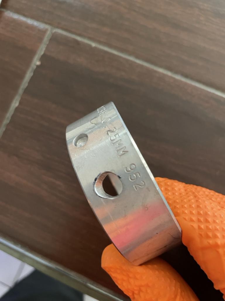 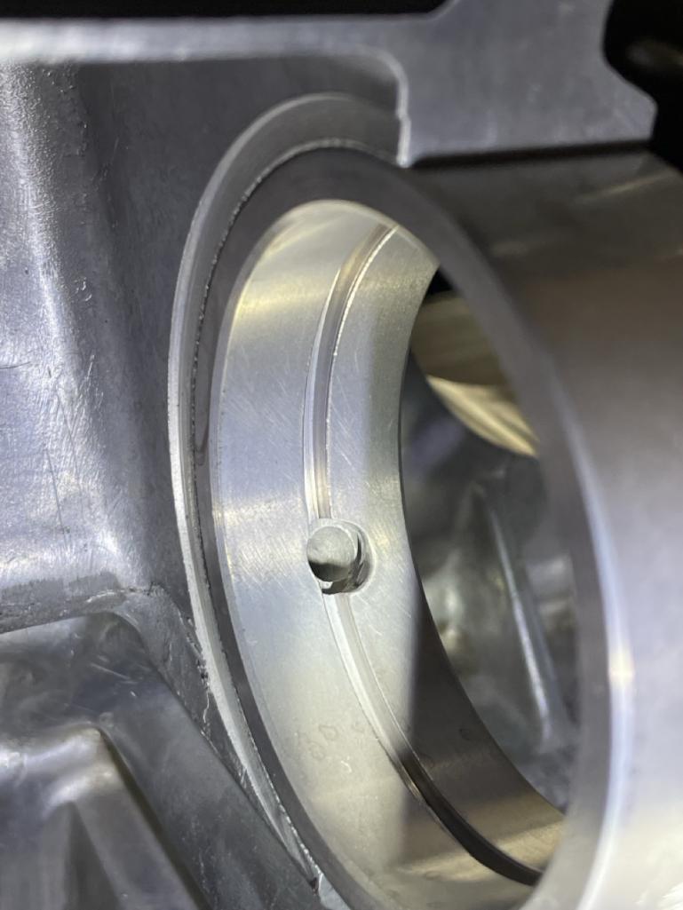  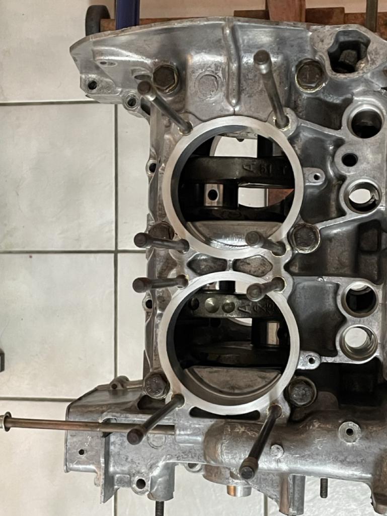
|
|
|
|
| Superhawk996 |
Nov 23 2025, 01:25 PM
Post
#19
|
|
914 Guru Group: Members Posts: 7,536 Joined: 25-August 18 From: Woods of N. Idaho Member No.: 22,428 Region Association: Galt's Gulch |
|
|
|
|
| Ninja |
Nov 23 2025, 01:48 PM
Post
#20
|
|
Newbie Group: Members Posts: 19 Joined: 25-September 25 From: Granbury Texas Member No.: 29,004 Region Association: Southwest Region |
The picture of the rear of the engine assembled shows large rectangular holes at the case parting lines (I couldn't quote the pics).
Are these drain back and vent holes ALA Jake Raby? If so, those are large! If not make sure to incorporate drain backs for the rear seal. This is a common mod. Lots of manufactures use them and when I have a badly leaking seal on ANYTHING the holes are usually gummed up! You do need both a drain and a vent (top and bottom). The most common failure I see is from a previous tech installing cam seals (T-belt engine) with RTV which blocks the holes. Sometimes a seal installed too deeply will do the same thing. |
|
|
|
|
1 User(s) are reading this topic (1 Guests and 0 Anonymous Users)
0 Members:

|
Lo-Fi Version | Time is now: 23rd November 2025 - 05:33 PM |
Invision Power Board
v9.1.4 © 2025 IPS, Inc.