|
|
|
Porsche, and the Porsche crest are registered trademarks of Dr. Ing. h.c. F. Porsche AG.
This site is not affiliated with Porsche in any way. Its only purpose is to provide an online forum for car enthusiasts. All other trademarks are property of their respective owners. |
|
|

  |

| 914rrr |
 Apr 28 2026, 10:46 PM Apr 28 2026, 10:46 PM
Post
#1
|
|
Advanced Member  Group: Members Posts: 2,073 Joined: 1-July 03 From: McMinnville, TN Member No.: 874 Region Association: South East States |
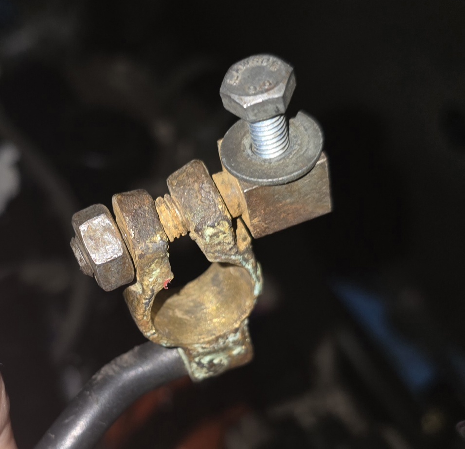
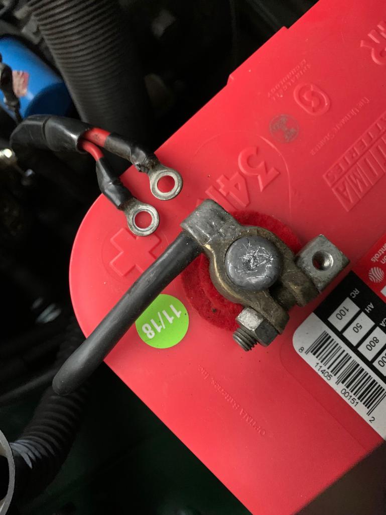
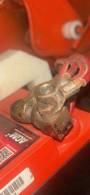
I have a sloppy DAPO red positive wires and cheapo aftermarket positive battery terminal situation and would appreciate best solution to tidy these up, make better connections, etc.
This also makes me curious about how 4-6 wires were originally run to the positive battery terminal from the factory. 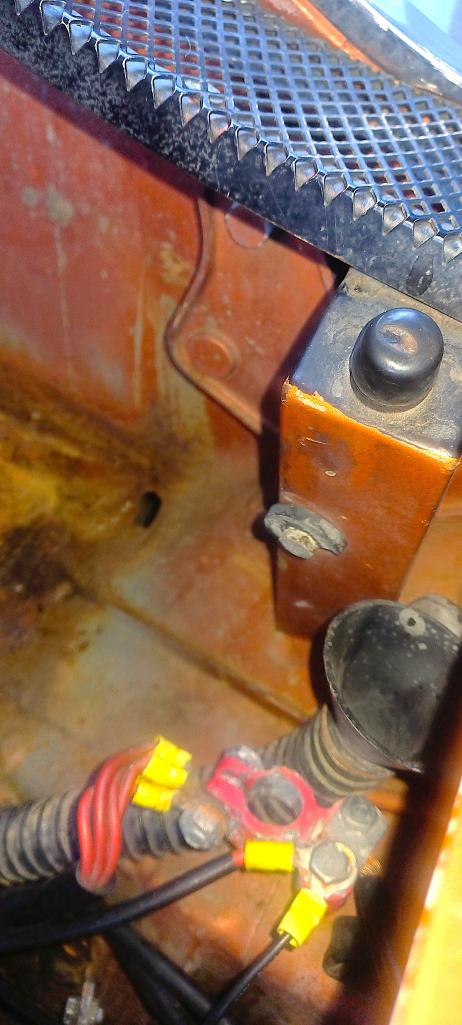 |
   |

 
|
| Krieger |
Apr 29 2026, 12:05 AM
Post
#2
|
|
Advanced Member Group: Members Posts: 4,864 Joined: 24-May 04 From: Santa Rosa CA Member No.: 2,104 Region Association: None |
It's called a battery block positive terminal. At least that is what 914 Rubber calls it on their website. Idk if its available wnywhere else.
 |
|
|
|
| Dlee6205 |
Apr 29 2026, 05:58 AM
Post
#3
|
|
Member Group: Members Posts: 97 Joined: 9-December 22 From: Burnsville, NC Member No.: 27,017 Region Association: South East States |
I hate those aftermarket battery terminals that clamp down on the cable.
This is my typical “aftermarket” solution. I change the connection block out for 1 with a stud. I put a ring terminal on the main battery cable going to the starter, and replace the connections on the red wires with insulted heat shrink connectors. In this case I also upgraded the cable going to the starter. 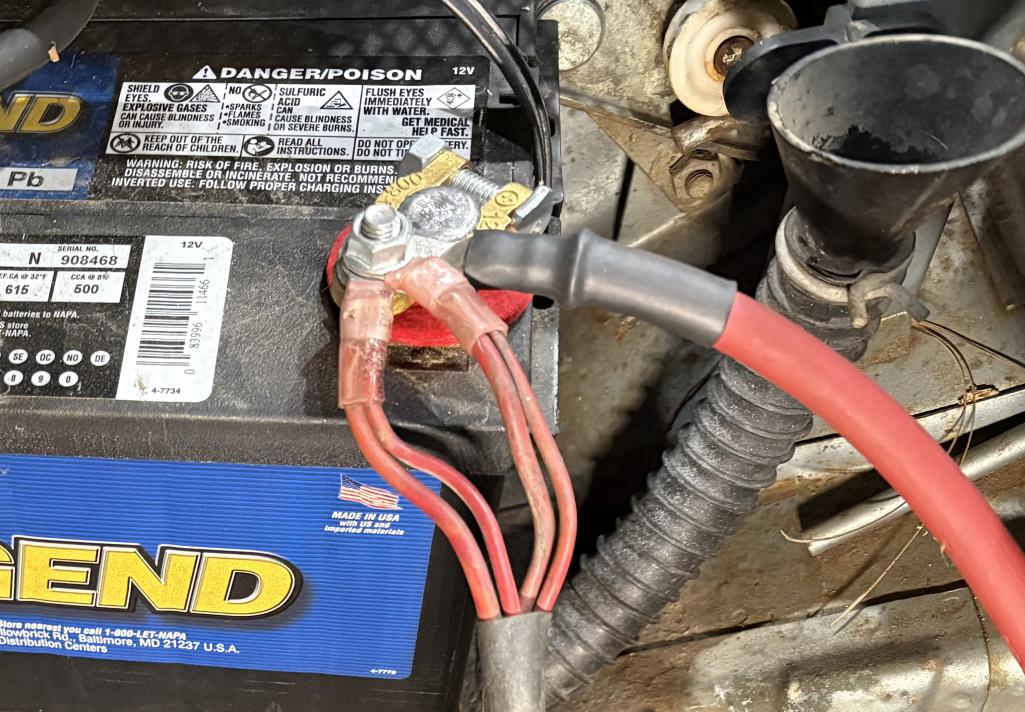 |
|
|
|
| Chad911sc |
Apr 29 2026, 06:31 AM
Post
#4
|
|
Member Group: Members Posts: 327 Joined: 24-September 24 From: Florida Member No.: 28,374 Region Association: South East States |
I went with these that I purchased from Amazon. Clean and tidy, well built. Just put the wires into the slots and use Allen wrench to lock in, no connectors to mess with. I think they were like 15 bucks if I remember correctly.
Attached thumbnail(s) 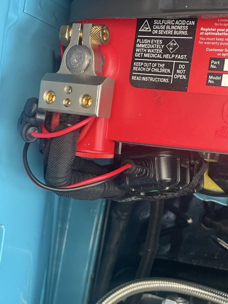
|
|
|
|
| burton73 |
Apr 29 2026, 10:43 AM
Post
#5
|
|
Senior member, and old dude Group: Members Posts: 4,038 Joined: 2-January 07 From: Los Angeles Member No.: 7,414 Region Association: Southern California |
Battery hook up PMB way
Best Bob B 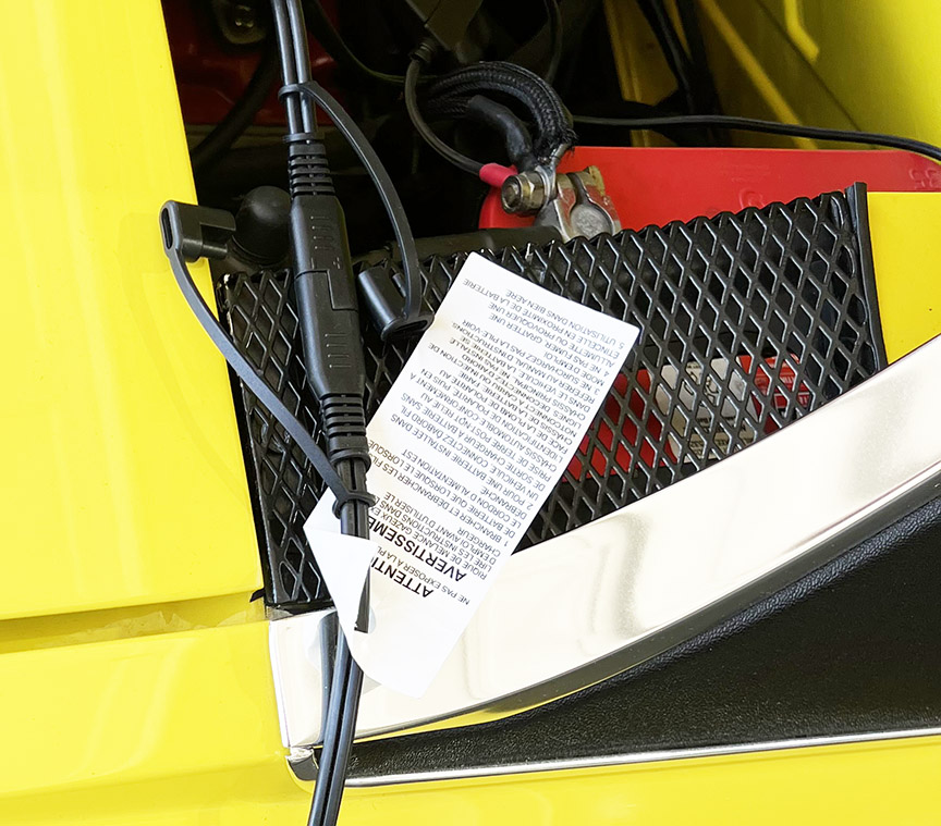 |
|
|
|
| mjrrti |
Apr 29 2026, 10:25 PM
Post
#6
|
|
High Desert Member Group: Members Posts: 67 Joined: 4-February 14 From: Apple Valley, Ca Member No.: 16,959 Region Association: Southern California |
QUOTE(914rrr @ Apr 28 2026, 09:46 PM)  I have a sloppy DAPO red positive wires and cheapo aftermarket positive battery terminal situation and would appreciate best solution to tidy these up, make better connections, etc. This also makes me curious about how 4-6 wires were originally run to the positive battery terminal from the factory. I used an automotive bus bar that I found on Amazon for around $10 on my Subaru conversion that has even more 10 ga wires that need to connect to my battery. 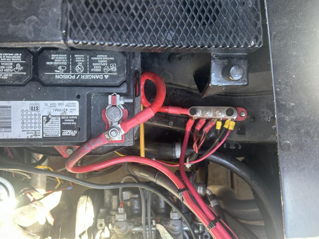 |
|
|
|
| barefoot |
Apr 30 2026, 06:06 AM
Post
#7
|
|
Senior Member Group: Members Posts: 1,521 Joined: 19-March 13 From: Charleston SC Member No.: 15,673 Region Association: South East States |
I took a different approach by installing a 1 in/4 out fuze block .
Now I sleep well at night (IMG:style_emoticons/default/rolleyes.gif) Barefoot 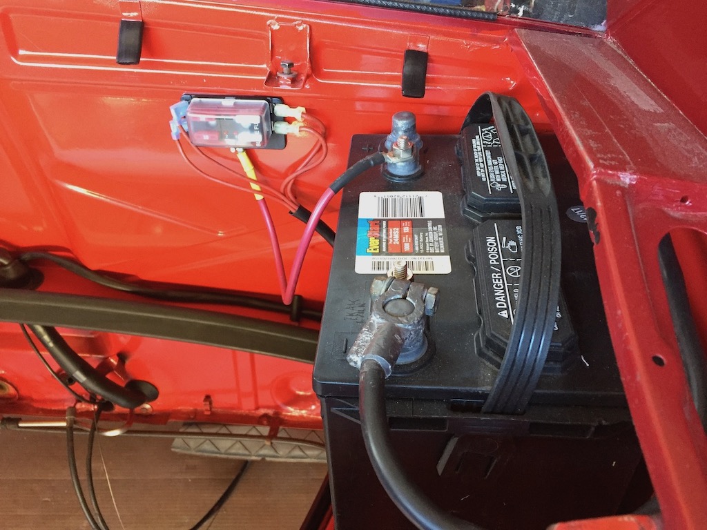 |
|
|
|
| TRP |
Apr 30 2026, 08:07 AM
Post
#8
|
|
Member Group: Members Posts: 407 Joined: 2-September 23 From: Morgan Hill, CA Member No.: 27,559 Region Association: None |
|
|
|
|
| FlacaProductions |
Apr 30 2026, 09:03 AM
Post
#9
|
|
Advanced Member Group: Members Posts: 2,240 Joined: 24-November 17 From: LA Member No.: 21,628 Region Association: Southern California |
I did what @barefoot did - but mine is mounted a bit differently. Same effect.
|
|
|
|
| Root_Werks |
Apr 30 2026, 09:12 AM
Post
#10
|
|
Village Idiot Group: Members Posts: 9,014 Joined: 25-May 04 From: About 15NM from Canada Member No.: 2,105 Region Association: Pacific Northwest |
If I remember correctly, the factory connected wires in pairs to a simple loop terminal that was screwed onto a block similar to what was shown earlier. Even from the factory, not the most elegant solution.
|
|
|
|
| TRP |
Apr 30 2026, 10:03 AM
Post
#11
|
|
Member Group: Members Posts: 407 Joined: 2-September 23 From: Morgan Hill, CA Member No.: 27,559 Region Association: None |
I agree with @Root_Werks, not the most elegant solution. From memory on my 1.8 L-Jet car (which may be wrong) - there are three ring terminals that connect to the block. Two pairs of wires (4 total) connected to two ring terminals from the main harness, with single wire / ring terminal coming from the ignition harness.
A few of the examples shown above represent a cleaner and safe approach to the same issue. |
|
|
|
| anderssj |
Apr 30 2026, 10:09 AM
Post
#12
|
|
Dog is my copilot... Group: Members Posts: 1,793 Joined: 28-January 03 From: VA Member No.: 207 Region Association: MidAtlantic Region |
 "as was" factory set up I also did what barefoot did (another slightly different approach): 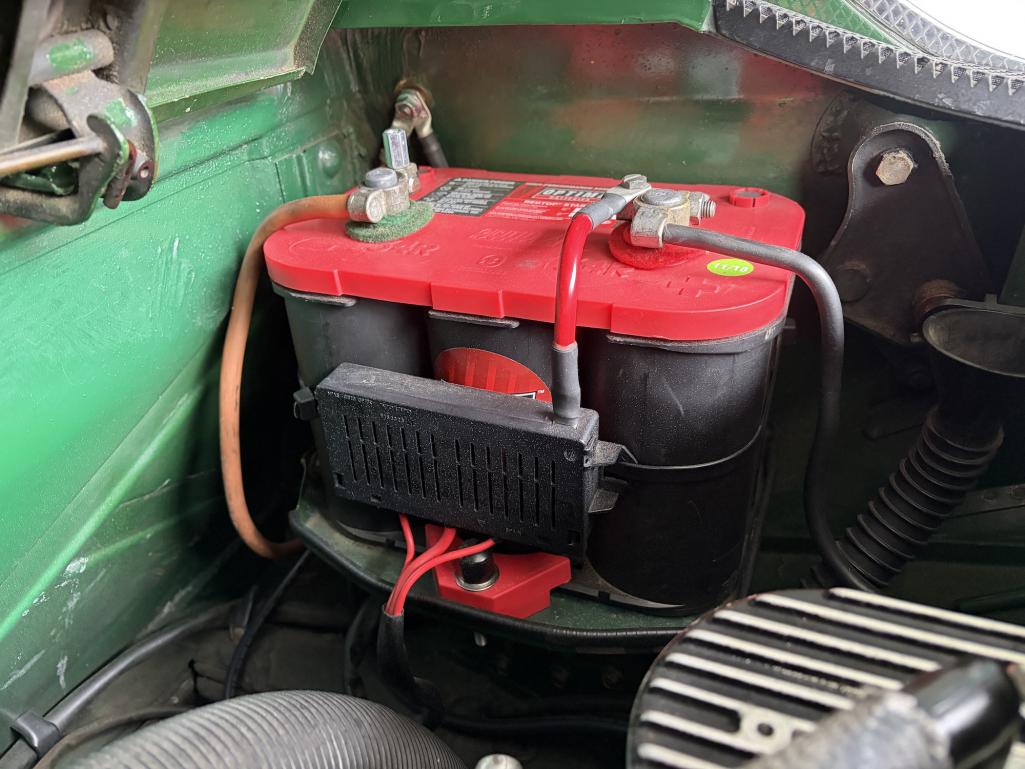 Black box was salvaged from an old Volvo. It's held to the battery with a big zip tie. Inside of box looks like this: 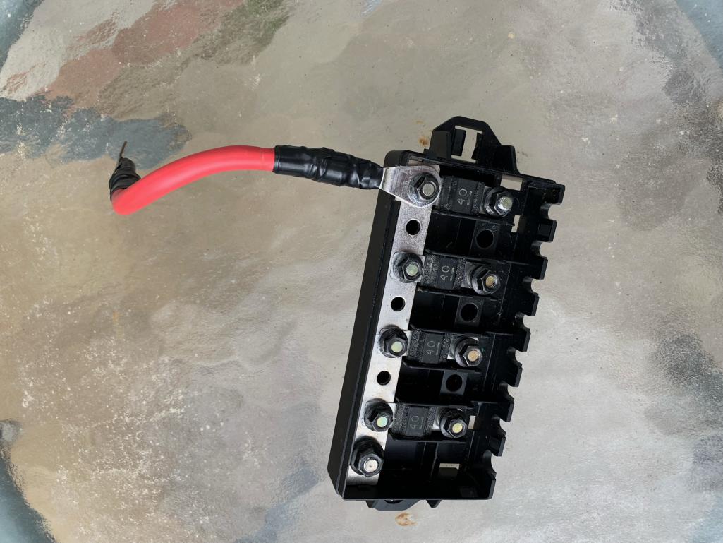 No cutting or drilling required. |
|
|
|
| burton73 |
Apr 30 2026, 02:40 PM
Post
#13
|
|
Senior member, and old dude Group: Members Posts: 4,038 Joined: 2-January 07 From: Los Angeles Member No.: 7,414 Region Association: Southern California |
One more shot of the clean way PMB did this
Best Bob B 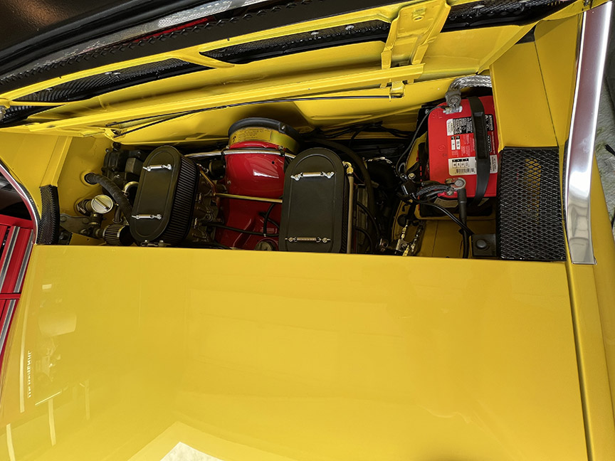 |
|
|
|
| Artfrombama |
Apr 30 2026, 06:33 PM
Post
#14
|
|
Artfrombama Group: Members Posts: 463 Joined: 21-January 24 From: One of the chosen few Member No.: 27,870 Region Association: South East States |
 |
|
|
|
| 914rrr |
May 1 2026, 03:43 PM
Post
#15
|
|
Advanced Member Group: Members Posts: 2,073 Joined: 1-July 03 From: McMinnville, TN Member No.: 874 Region Association: South East States |
QUOTE(Artfrombama @ Apr 30 2026, 07:33 PM) Q; how did the factory mount those 2 ring terminals to the square block + stud? Hard to tell from the pic. Also, did the factory simply crush 2 wires together in one ring terminal or did they put solder on them before crimping, or simply solder the 2 wires to the ring terminal? |
|
|
|
| 914rrr |
May 1 2026, 03:50 PM
Post
#16
|
|
Advanced Member Group: Members Posts: 2,073 Joined: 1-July 03 From: McMinnville, TN Member No.: 874 Region Association: South East States |
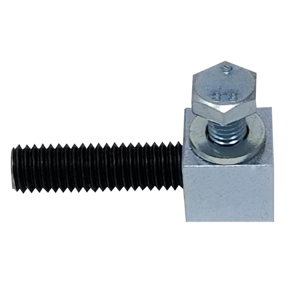
What I'm thinking of using is this terminal I found at Wally World and these ring terminals I had in my stash.
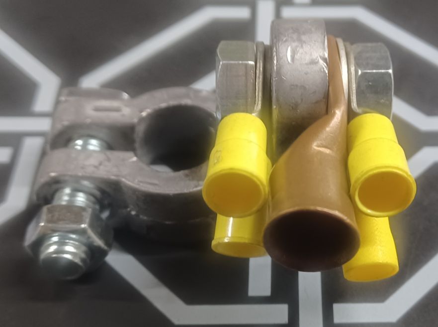 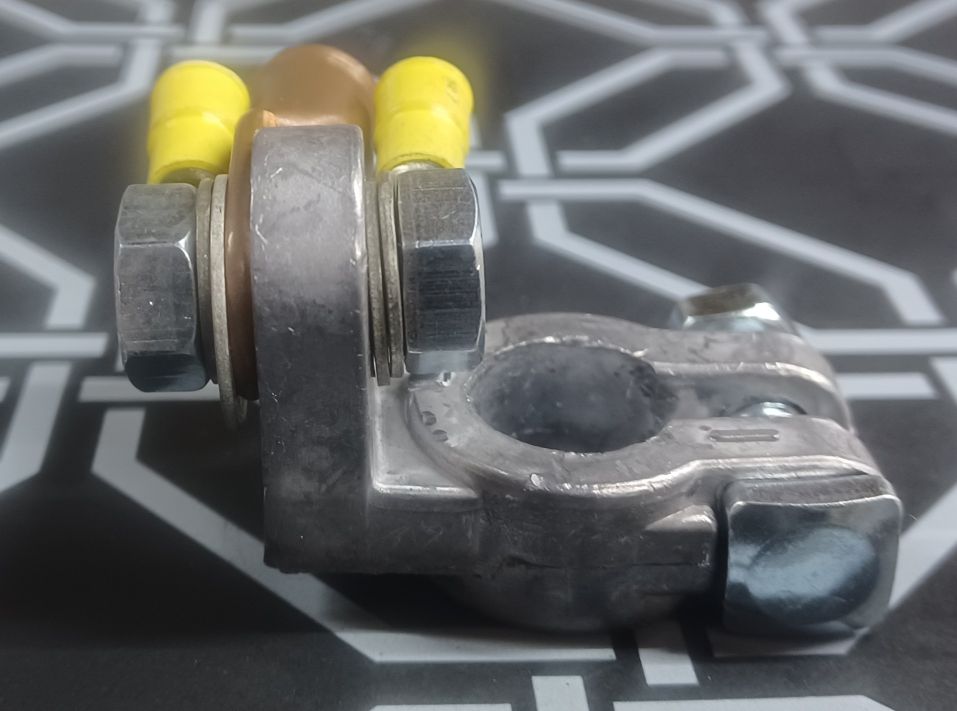 Another option are these 4 way connectors. Are these legit? 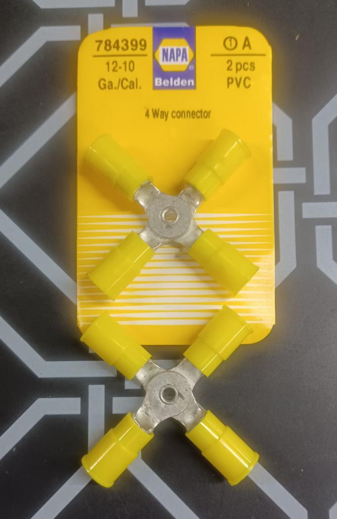 |
|
|
|
| 914rrr |
May 1 2026, 03:58 PM
Post
#17
|
|
Advanced Member Group: Members Posts: 2,073 Joined: 1-July 03 From: McMinnville, TN Member No.: 874 Region Association: South East States |
This pic brings up another question.
The OG 4 red wires go into the harness bundle, correct? Then why do I have 6 wires going to my positive terminal? I think one of the additional wires goes to the FI dual relay. Is power to the FI dual relay supposed to come from someplace else, like the engine bay relay board / plate? The other is power for the trunk solenoid, I think. 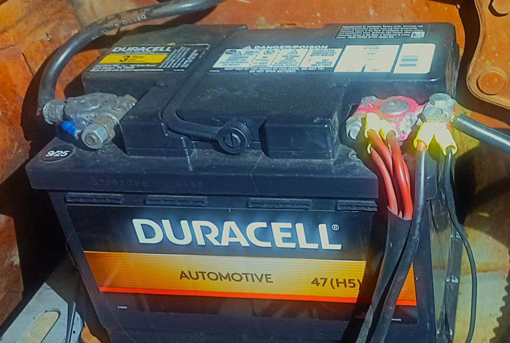 |
|
|
|
| 930cabman |
May 1 2026, 05:59 PM
Post
#18
|
|
Advanced Member Group: Members Posts: 4,728 Joined: 12-November 20 From: Buffalo Member No.: 24,877 Region Association: North East States |
QUOTE(Root_Werks @ Apr 30 2026, 09:12 AM) If I remember correctly, the factory connected wires in pairs to a simple loop terminal that was screwed onto a block similar to what was shown earlier. Even from the factory, not the most elegant solution. (IMG:style_emoticons/default/agree.gif) somewhat of a "Rube" from the factory, but if maintained they work ok |
|
|
|
| JeffBowlsby |
May 2 2026, 07:18 AM
Post
#19
|
|
914 Wiring Harnesses & Beekeeper Group: Members Posts: 9,293 Joined: 7-January 03 From: San Ramon CA Member No.: 104 Region Association: None |
At the battery:
70-72 914s had 3 red wires 73-74 914s had 4 red wires |
|
|
|
| wonkipop |
May 4 2026, 04:03 AM
Post
#20
|
|
914 Guru Group: Members Posts: 5,573 Joined: 6-May 20 From: north antarctica Member No.: 24,231 Region Association: NineFourteenerVille |
i sorted this out on mine a couple of months ago with something that kind of simulated the original set up. 1.8 L jet. might try and take some photos to post tomorrow.
|
|
|
|
|
1 User(s) are reading this topic (1 Guests and 0 Anonymous Users)
0 Members:

|
Lo-Fi Version | Time is now: 29th June 2026 - 12:54 AM |
Invision Power Board
v9.1.4 © 2026 IPS, Inc.