|
|
|
Porsche, and the Porsche crest are registered trademarks of Dr. Ing. h.c. F. Porsche AG.
This site is not affiliated with Porsche in any way. Its only purpose is to provide an online forum for car enthusiasts. All other trademarks are property of their respective owners. |
|
|

  |

| Mike1981 |
 May 10 2026, 08:15 AM May 10 2026, 08:15 AM
Post
#21
|
|
Member  Group: Members Posts: 278 Joined: 21-July 14 From: Phoenix Member No.: 17,663 Region Association: South East States |
Hi
Appreciate your observation about changes on the fuse wiring. Could you please point me to what was changed? thanks |
   |

 
|
| Mike1981 |
May 10 2026, 08:47 AM
Post
#22
|
|
Member Group: Members Posts: 278 Joined: 21-July 14 From: Phoenix Member No.: 17,663 Region Association: South East States |
Hi
Appreciate your observation about changes on the fuse wiring. Could you please point me to what was changed? thanks |
|
|
|
| mgphoto |
May 10 2026, 09:42 AM
Post
#23
|
|
"If there is a mistake it will find me" Group: Members Posts: 1,475 Joined: 1-April 09 From: Los Angeles, CA Member No.: 10,225 Region Association: Southern California |
QUOTE(Mike1981' my date='May 10 2026, 06:47 AM @ May 10 2026, 06:47 AM)  Hi Appreciate your observation about changes on the fuse wiring. Could you please point me to what was changed? thanks The wires I circled in yellow have been cut and repaired the black shrink wrap looks pro the crimped one PO probably. They are white. 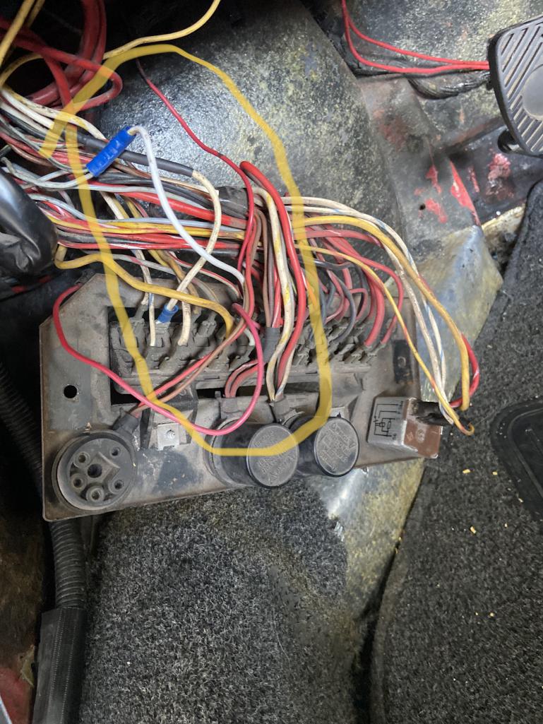 |
|
|
|
| Spoke |
May 10 2026, 11:26 AM
Post
#24
|
|
Jerry Group: Members Posts: 7,390 Joined: 29-October 04 From: Allentown, PA Member No.: 3,031 Region Association: None |
Here's the pinout for EP26 and OEM flasher relays. I've marked those pins on your picture. Standard flasher relays have Power (49), Ground (31) and output (49a)
There is no connection to ground and there's a wire connected to C2 which likely is doing nothing. If you want to see if this flasher relay will function, follow the wires from this connector to the flasher relay and correct the C2 and 31 wires. 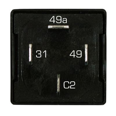 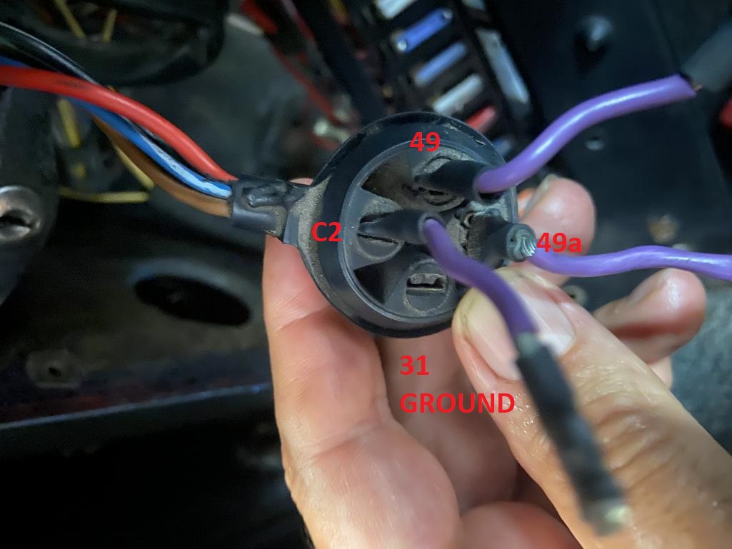 |
|
|
|
| Mike1981 |
May 11 2026, 09:05 AM
Post
#25
|
|
Member Group: Members Posts: 278 Joined: 21-July 14 From: Phoenix Member No.: 17,663 Region Association: South East States |
Wow
Thanks very much for the help Spoke and Mgphoto, the diagrams help immensely. Spoke, I ordered your relay and am waiting for confirmation/payment info. Are you suggesting I short C2 and 31 to test relay? If you want to see if this flasher relay will function, follow the wires from this connector to the flasher relay and correct the C2 and 31 wires Also no ground connection for the relay? This schematic shows Brown to Ground. Attached image(s) 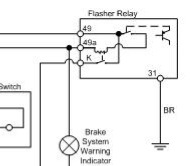
|
|
|
|
| Spoke |
May 12 2026, 10:34 AM
Post
#26
|
|
Jerry Group: Members Posts: 7,390 Joined: 29-October 04 From: Allentown, PA Member No.: 3,031 Region Association: None |
QUOTE(Mike1981 @ May 11 2026, 11:05 AM) Wow Thanks very much for the help Spoke and Mgphoto, the diagrams help immensely. Spoke, I ordered your relay and am waiting for confirmation/payment info. Are you suggesting I short C2 and 31 to test relay? If you want to see if this flasher relay will function, follow the wires from this connector to the flasher relay and correct the C2 and 31 wires Also no ground connection for the relay? This schematic shows Brown to Ground. Mike, did you order from me on 5/9? That order from a Mike was for the later '74-'76 mod. You have an early tach with separate L and R indicators, correct? For your current setup, you do not need to ground C2 just to see if you have flashing. Check the pins on the existing flasher relay and put 49 (power), 49a (output), and 31 (ground). This would be just to make sure the wiring is ok. |
|
|
|
|
2 User(s) are reading this topic (2 Guests and 0 Anonymous Users)
0 Members:

|
Lo-Fi Version | Time is now: 14th May 2026 - 01:34 AM |
Invision Power Board
v9.1.4 © 2026 IPS, Inc.