

 Fred's 2374 -> 2258 Engine Build Thread Fred's 2374 -> 2258 Engine Build Thread |
|
|

|
Porsche, and the Porsche crest are registered trademarks of Dr. Ing. h.c. F. Porsche AG.
This site is not affiliated with Porsche in any way. Its only purpose is to provide an online forum for car enthusiasts. All other trademarks are property of their respective owners. |
|
|
  |
| zig-n-zag |
 Jul 17 2026, 05:02 PM Jul 17 2026, 05:02 PM
Post
#101
|
|
Member  Group: Members Posts: 219 Joined: 18-May 06 From: Hawaii Member No.: 6,024  |
The “initial mock-up test fit” and “case gauge” comment triggered a memory on how I was told to determine if a case was still good or not.
Say you came across a used Type 4 engine for sale which was complete and still together. Check the 6 case bolts if they are still torqued to factory spec. If they are, then torque those case bolts to 30 ftlbs. The crank should still turn smoothly. Any binding means the case would need a line-bore. If the nuts were loose, inspect the case saddles. The original machining marks should be visible. If not, then line-bore. Yes, you can check by installing a crank with bearings and do the 30lbs test, and it will probably pass. But if built, when the engine comes up to operating temperature, it may seize. |
   |

 
|
| 930cabman |
Jul 17 2026, 05:58 PM
Post
#102
|
|
Advanced Member Group: Members Posts: 4,833 Joined: 12-November 20 From: Buffalo Member No.: 24,877 Region Association: North East States 
|
QUOTE(friethmiller @ Jul 17 2026, 01:24 PM)  Do I have to run the AFR gauge into the main cabin? This cable is thick. Would it be sufficient just run it into the engine bay and put the gauge there? I know it's not a gauge that you don't need all the time. Opinions welcome? I purchased an Innovate LM 2 several years ago, just recently got it connected successfully (connected into the cabin), it is showing rich under 3k rpms telling me the idle circuit needs to be leaned out. In the past I have relied on the color of spark plugs for AFR. Has worked ok for me, but I am far from a dyed in the wool tuner, more like seat of the pants. I like having a tube fed oil pressure gauge and a capillary tube temp gauge in the cabin. BUT, my builds are stock, nothing out of the ordinary. I'll bet cylinder head temps are also important |
|
|
|
| Jack Standz |
Jul 17 2026, 07:39 PM
Post
#103
|
|
Senior Member Group: Members Posts: 925 Joined: 15-November 19 From: Happy Place (& surrounding area) Member No.: 23,644 Region Association: None
|
QUOTE(friethmiller @ Jul 18 2026, 02:24 AM) Do I have to run the AFR gauge into the main cabin? This cable is thick. Would it be sufficient just run it into the engine bay and put the gauge there? I know it's not a gauge that you don't need all the time. Opinions welcome? Fred. Are you messing with us? (IMG:style_emoticons/default/biggrin.gif) Don't see how the gauge does you any good if you can't see it. So, yes in the main cabin where you can take note of AFRs under load, at different RPMs, WOT, going downhill, at cruise, etc. An AFR gauge really helps dial in carbs, idle jets, main jets, air correction, emulsion tubes, pump jets, venturis, etc. With all the possible combinations of adjustments, it is an iterative process, so you'll want to note how your changes affect the AFRs. Then at some point you say things are "good enough", especially if you regularly run the car at sea level and at altitude. Until then, it's a gauge you're always watching. |
|
|
|
| friethmiller |
Jul 17 2026, 08:45 PM
Post
#104
|
|
Senior Member Group: Members Posts: 1,531 Joined: 10-February 19 From: Austin, TX Member No.: 22,863 Region Association: Southwest Region
|
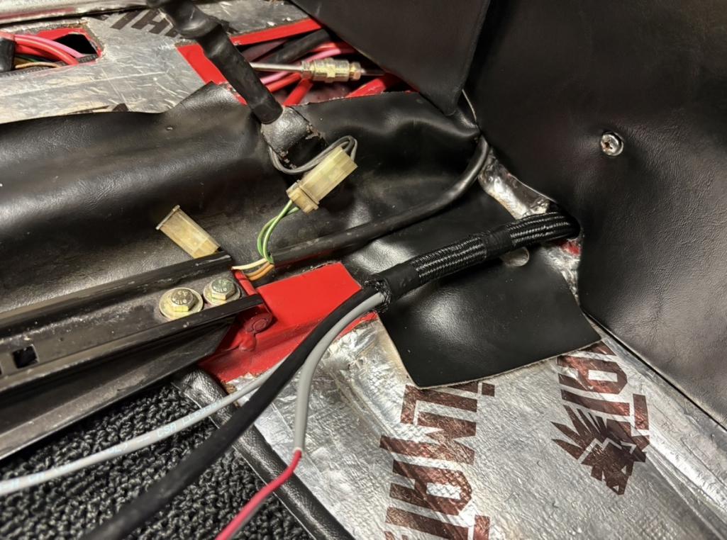
Yeah that doesn’t make sense for an AFR. Can’t really see back there while you’re driving. I was looking at the wrong end of the cable and thinking “how in the world am I going to get this huge connector through the firewall". Luckily the other end was much smaller. I’ve already routed it with the CHT wires up under the console. Next, I need to figure out exactly how/where I going to mount the gauges.
 |
|
|
|
| friethmiller |
Aug 14 2026, 08:24 AM
Post
#105
|
|
Senior Member Group: Members Posts: 1,531 Joined: 10-February 19 From: Austin, TX Member No.: 22,863 Region Association: Southwest Region
|
Quick Update:
Brothers VW Machine in CA was able to verify and fix the problem. They lightly polish my new crankshaft to provide the correct clearances for my EC case. If you recall, the parting line oil clearances were the issue with this case. I will of course verify things again once it's back in the garage. The case, bearings, and crank will likely return the middle of next week. So, next weekend will be set aside for getting [re]started. (IMG:style_emoticons/default/cheer.gif) |
|
|
|
| friethmiller |
Aug 22 2026, 10:12 PM
Post
#106
|
|
Senior Member Group: Members Posts: 1,531 Joined: 10-February 19 From: Austin, TX Member No.: 22,863 Region Association: Southwest Region
|
Engine Assembly - Part 1 (8/22/2026):
With the case, crank, and bearings back from Brothers VW Machine, I quickly verified measurements and then completely rewashed the case halves to get ready for assembly. The guys had lightly ground my new crankshaft to provide a bit more oil clearance. I did have an issue with measuring the #2 main but I verified it was just my measurements of the crank journal OD and I verified it with some pastigauge. 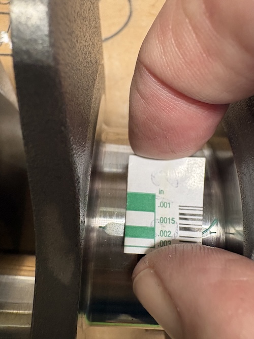 With everything cleaned, I set out to slide on the gears and test fit everything into the case. Even with the case torqued, everything felt good, no issues rotating the crank with one hand. I did trade out one of the thrust bearings on the cam. One half was too tight so I swapped it out with a spare. I am running a double thrust for this application, of course. 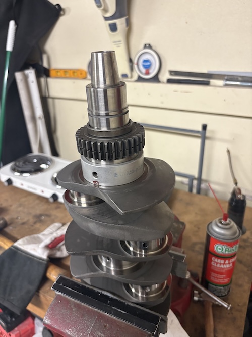 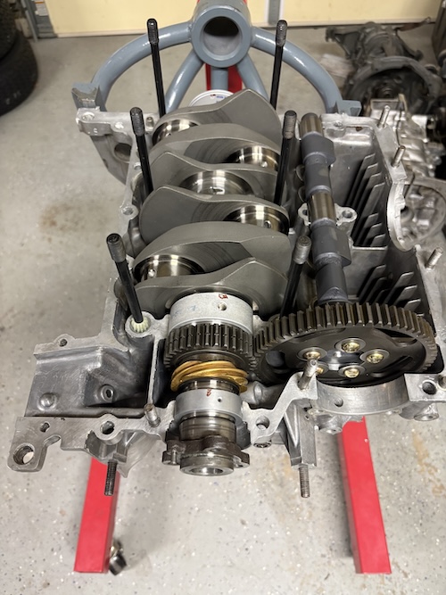 I then pulled everything back apart and cleaned and installed the rods that were already to go. 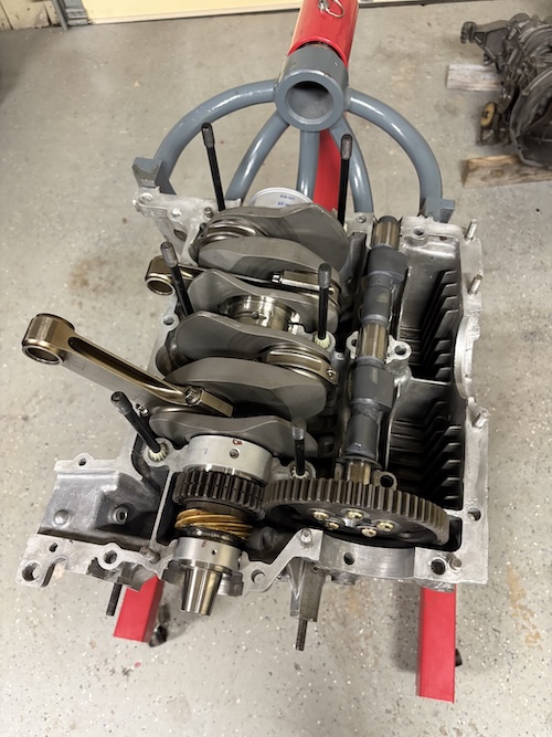 Again, the case was reassembled and torqued. This time I proceeded by installing all of the head studs using the permatex thread sealant. Next, I added pistons & cylinders for 1&2 (without rings) and got things ready for degreeing in the cam. The timing wheel I was using wasn't really made for VW engines and I had to remove the air/fan shroud studs to properly "clamp" the wheel with the crank bolt. I also used a short section of a clothes hanger to act as a pointer. Pretty easy to do. So after watching about 6 different Cam Degreeing videos, I felt like I might actually understand what I had to do and why I was taking these measurements. (IMG:style_emoticons/default/beer.gif) First step of the process was finding true TDC, which was roughed in by eye and then adjusted by going .050 in either direction to verify my zero (TDC). 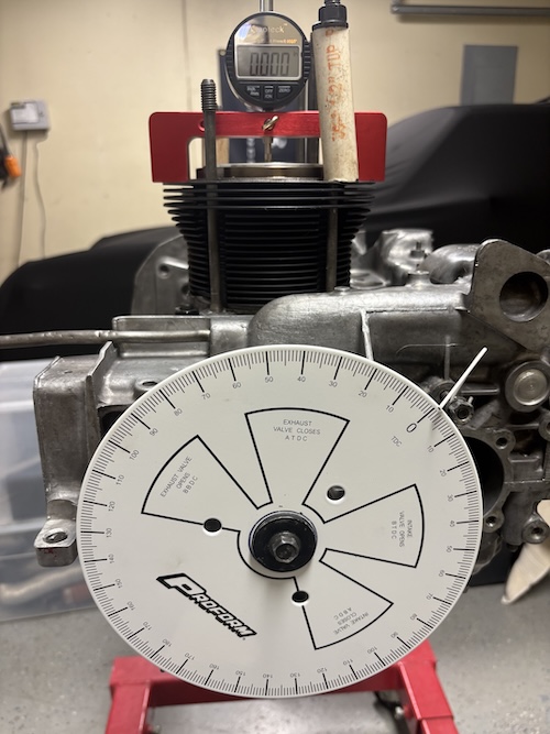 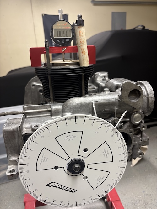 With this initial task complete, I then moved over to setting up something to measure intake lift using a installed lifter. To set this up, I cut a piece of 16 gauge sheet metal to allow my magnetic base to clamp down to something. I used the 10mm studs on the side of the case that normally secure the thermostat. The next job to do was to measure max intake lift. And here's where things got off track a bit for me. I was getting lift measurements that were low and I couldn't figure out why initially. It turned out the two small bolts that my base was secured to were not enough to prevent the entire stand from moving during this measurement. I think If I had secured the base using a third bolt somewhere, I probably wouldn't have had the issue. To get past the problem, I simply jammed a box wrench between the base on the engine case to prevent things from moving. Another issue was the reach of the dial gauge. It wasn't long enough to reach far enough into the lifter bore to take any measurements at all. There just too much stuff in the way. I got around this problem by stacking a second lifter in the bore. This worked great for me but I'm sure a longer pointer would be available for purchase for the bore gauge. With all the bandaid fixes deployed, I was finally able to get a measurement of .3895 which is just shy of .390 that, when multiplied by the 1.3 rocker arm ratio matches the targeted .507 of valve lift. (IMG:style_emoticons/default/cheer.gif) 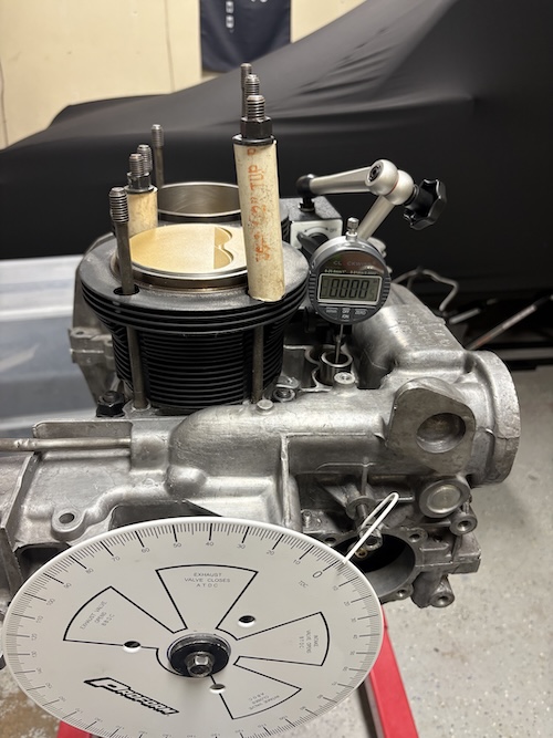 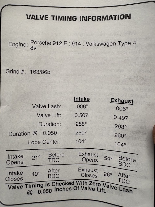 Once you have max valve lift, you can then find your lobe center. This is where I zeroed the dial gauge at max lift and then rotated the cam wheel .050" in either direction taking the degree measurements. For this I got 145 and 59 degrees. Adding them together, I got 204 degrees and then dividing this number by 2 and got an intake lobe center of 102 degrees. I know that if the number is less than the expected value of 104 degrees, the cam is "advanced" by 2 degrees. I think 2-4 degrees would be ideal for street use and might be good to go here. More measuring coming soon. Cheers! (IMG:style_emoticons/default/beerchug.gif) 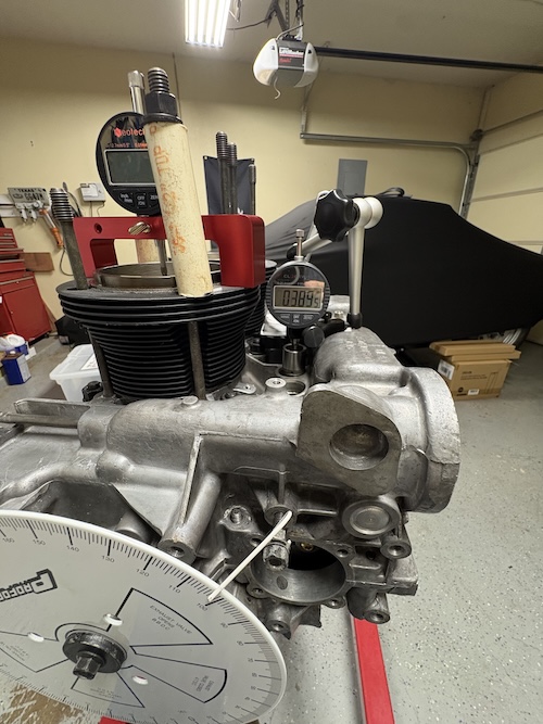 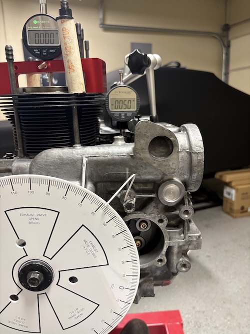 |
|
|
|
| seanpaulmc |
Aug 23 2026, 05:44 AM
Post
#107
|
|
Member Group: Members Posts: 463 Joined: 6-December 16 From: Orlando, FL Member No.: 20,649 Region Association: South East States
|
You’ll be driving to Okteenerfest, Fred! (IMG:style_emoticons/default/driving.gif)
|
|
|
|
| 930cabman |
Aug 23 2026, 06:06 AM
Post
#108
|
|
Advanced Member Group: Members Posts: 4,833 Joined: 12-November 20 From: Buffalo Member No.: 24,877 Region Association: North East States
|
lookin good, have you torqued the case together and checked the crank "feel"
|
|
|
|
| friethmiller |
Aug 23 2026, 06:24 AM
Post
#109
|
|
Senior Member Group: Members Posts: 1,531 Joined: 10-February 19 From: Austin, TX Member No.: 22,863 Region Association: Southwest Region
|
Yeah, the crank feels good/rotates without any binding with the case bolts torqued. I still need to do more cam measurements this morning but will be splitting the case to locktite the cam bolts, insert the o-ringed oil pump, etc. before beginning the process of sealing the case together.
|
|
|
|
| friethmiller |
Aug 23 2026, 07:35 AM
Post
#110
|
|
Senior Member Group: Members Posts: 1,531 Joined: 10-February 19 From: Austin, TX Member No.: 22,863 Region Association: Southwest Region
|
QUOTE(seanpaulmc @ Aug 23 2026, 06:44 AM) Wouldn't that be wonderful! (IMG:style_emoticons/default/idea.gif) Let's call it a "long shot", for now. |
|
|
|
| Ninja |
Aug 23 2026, 08:05 AM
Post
#111
|
|
Member Group: Members Posts: 312 Joined: 25-September 25 From: Granbury Texas Member No.: 29,004 Region Association: Southwest Region |
That's just BS!!!!!
Fred only has to do it ONCE!!!! Not fair!!!! Looks GREAT! I'd leave it where it is... (IMG:style_emoticons/default/first.gif) |
|
|
|
| friethmiller |
Aug 23 2026, 08:46 AM
Post
#112
|
|
Senior Member Group: Members Posts: 1,531 Joined: 10-February 19 From: Austin, TX Member No.: 22,863 Region Association: Southwest Region
|
Ok, intake duration measured .05 open at 23 degrees before TDC and closes (0.05) after BDC at 47 degrees. That’s (23+47+180)/2 = 250 degrees of duration. That’s spot on! Exhaust is next.
|
|
|
|
| friethmiller |
Aug 23 2026, 08:53 AM
Post
#113
|
|
Senior Member Group: Members Posts: 1,531 Joined: 10-February 19 From: Austin, TX Member No.: 22,863 Region Association: Southwest Region
|
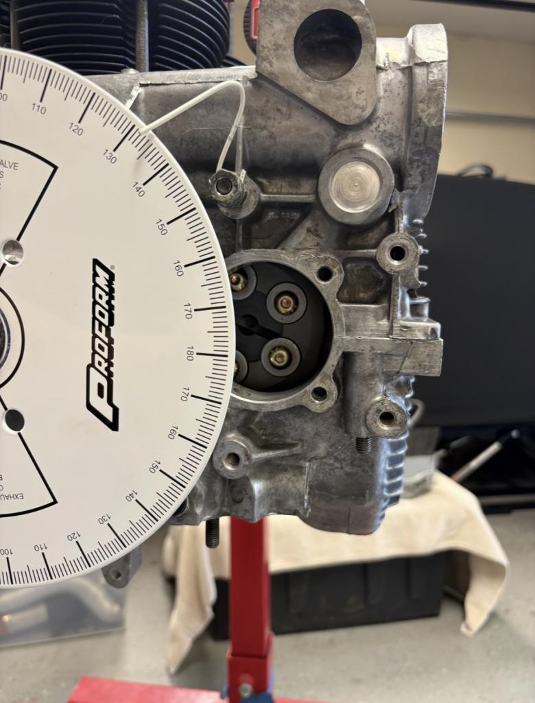
@Jack Standz, note I’m using a 9inch wheel here. Anything larger would probably get in the way of easily replacing the offset washers on the cam. I’m good with splitting the case again for the oil pump install but with a normal pump you could just install it and move on.
 |
|
|
|
| 930cabman |
Aug 23 2026, 09:33 AM
Post
#114
|
|
Advanced Member Group: Members Posts: 4,833 Joined: 12-November 20 From: Buffalo Member No.: 24,877 Region Association: North East States
|
I would take my time, check and double check everything
Go Fred go great project, thanks for posting |
|
|
|
| friethmiller |
Aug 23 2026, 09:36 AM
Post
#115
|
|
Senior Member Group: Members Posts: 1,531 Joined: 10-February 19 From: Austin, TX Member No.: 22,863 Region Association: Southwest Region
|
Exhaust:
Calculated max lift of .496 Lobe center: 108 degrees Duration: 262 degrees That’s an ICL of 105.5 ATDC and an ECL of 103.5 BTDC LSA = (105.5 + 103.5)/2 =104.5 |
|
|
|
| friethmiller |
Aug 24 2026, 08:59 AM
Post
#116
|
|
Senior Member Group: Members Posts: 1,531 Joined: 10-February 19 From: Austin, TX Member No.: 22,863 Region Association: Southwest Region
|
Building up the Short Block (8/23/2026):
First pic shows the base I made for my dial gauge stand. At 16 gauge, it just wasn't thick enough and it needed a third point to really lock it down and keep it from moving ever so slightly. 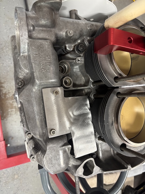 Before tearing everything down, I took the opportunity to get a rough sense of the shims I would need to order to set the proper deck height. You can see how a longer 78mm crank pushes the piston above the top of the cylinder. I'm basically plus .065. 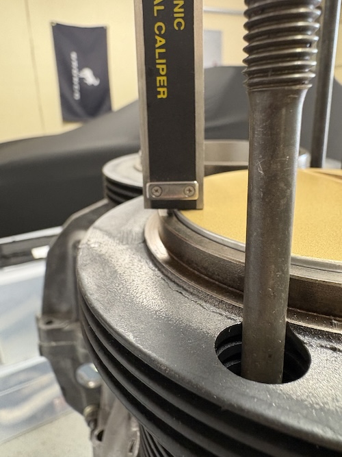 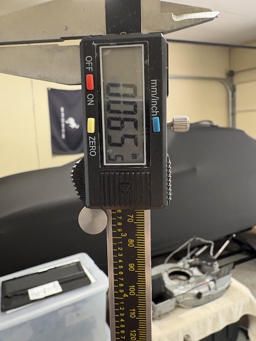 With the cam properly degreed, it was time to prep everything for the final install of the case halves. I had to loctite in the cam bolts, test fit the oil pump, insert/index the distributor, lubricate everything that needed oiled, and clean-up mating surfaces. Here's a few photos. 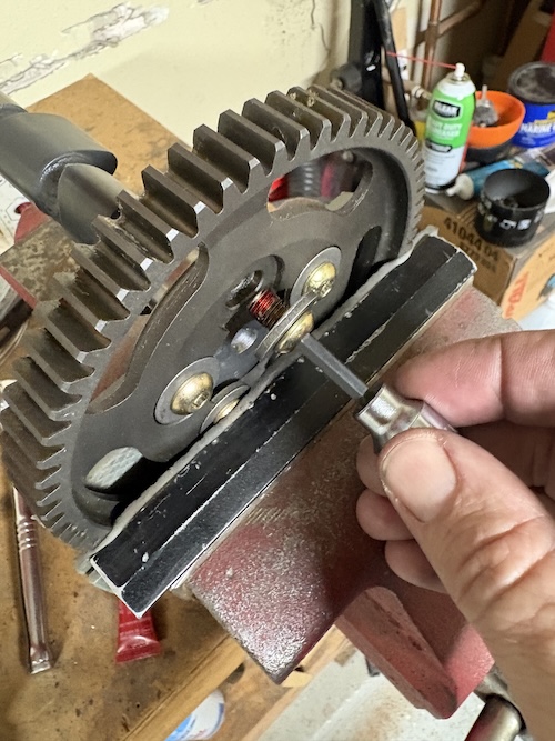 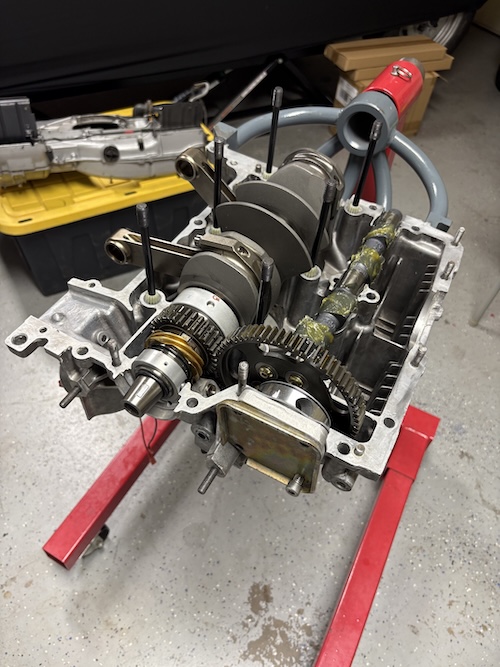 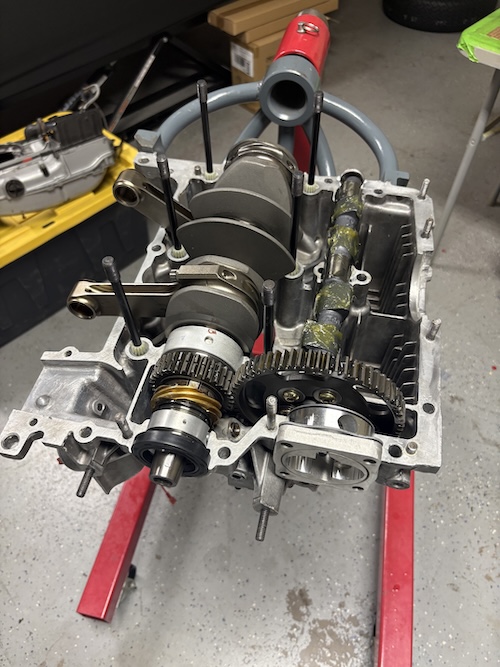 Here's the assembled short block. I did run into a problem with the oil pump. It was already clearanced for the cam bolts but the snout of the pump was actually bottoming out where the drive gear locks into the center of the cam. And it only happened once the pump was torqued. And it locked the cam/crank solid too! Scared the crap out of me. (IMG:style_emoticons/default/blink.gif) Not surprised, though. I've never worked with these special straight cut sprockets before. I work to get this problem solved next. More on this soon. 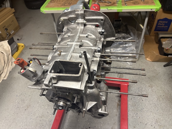 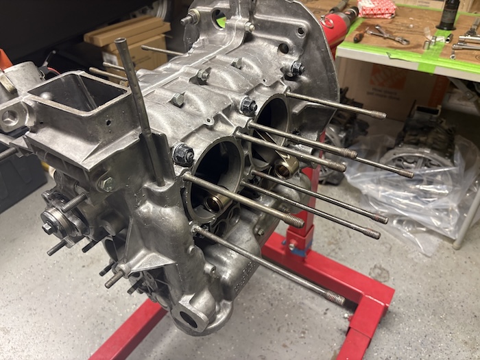 |
|
|
|
| Jack Standz |
Aug 24 2026, 12:52 PM
Post
#117
|
|
Senior Member Group: Members Posts: 925 Joined: 15-November 19 From: Happy Place (& surrounding area) Member No.: 23,644 Region Association: None
|
QUOTE(friethmiller @ Aug 23 2026, 09:53 PM) @Jack Standz, note I’m using a 9inch wheel here. Anything larger would probably get in the way of easily replacing the offset washers on the cam. I’m good with splitting the case again for the oil pump install but with a normal pump you could just install it and move on. Hi Fred, thanks for the info and photo. Not sure how large the diameter our degree wheel is, but will check. Think it's a Moroso. Also, we have a straight cut set of cam gears too for the 2615 project. Because we think the thrust bearings would take a beating using helical cam gears (even though we modified a set). Still wish a larger LSA cam was available, at least as an option. But, since they aren't available, one less decision to make (IMG:style_emoticons/default/biggrin.gif) We appreciate you for documenting your build and sharing . Thanks! |
|
|
|
| friethmiller |
Aug 24 2026, 01:39 PM
Post
#118
|
|
Senior Member Group: Members Posts: 1,531 Joined: 10-February 19 From: Austin, TX Member No.: 22,863 Region Association: Southwest Region
|
QUOTE(Jack Standz @ Aug 24 2026, 01:52 PM) ... Also, we have a straight cut set of cam gears too for the 2615 project. Because we think the thrust bearings would take a beating using helical cam gears (even though we modified a set). Still wish a larger LSA cam was available, at least as an option. But, since they aren't available, one less decision to make (IMG:style_emoticons/default/biggrin.gif) We appreciate you for documenting your build and sharing . Thanks! Sure thing! Please avoid all my missteps and mistakes (IMG:style_emoticons/default/bootyshake.gif) My heads are mod'd pretty good and are running double springs so I'm going with the noisy gears. Stay tuned to how I figure out my clearance issue with the oil pump. The metal must come off from the pump and/or the bolt heads. I've got the bolts in with red loctite now (IMG:style_emoticons/default/headbang.gif) so heating them to 500F to back them out might not be an option. I hope to not have to split the case either. We'll see. |
|
|
|
| porschetub |
Aug 25 2026, 12:21 AM
Post
#119
|
|
914 Guru Group: Members Posts: 5,175 Joined: 25-July 15 From: New Zealand Member No.: 18,995 Region Association: None |
QUOTE(friethmiller @ Aug 25 2026, 07:39 AM) QUOTE(Jack Standz @ Aug 24 2026, 01:52 PM) ... Also, we have a straight cut set of cam gears too for the 2615 project. Because we think the thrust bearings would take a beating using helical cam gears (even though we modified a set). Still wish a larger LSA cam was available, at least as an option. But, since they aren't available, one less decision to make (IMG:style_emoticons/default/biggrin.gif) We appreciate you for documenting your build and sharing . Thanks! Sure thing! Please avoid all my missteps and mistakes (IMG:style_emoticons/default/bootyshake.gif) My heads are mod'd pretty good and are running double springs so I'm going with the noisy gears. Stay tuned to how I figure out my clearance issue with the oil pump. The metal must come off from the pump and/or the bolt heads. I've got the bolts in with red loctite now (IMG:style_emoticons/default/headbang.gif) so heating them to 500F to back them out might not be an option. I hope to not have to split the case either. We'll see. Great progress, question is the relief cut (vee ) in the driven gear to reduce oil foaming or some reduction in noise ? , don't know much about these conversions but the T1 guys mentioned increased noise ? thanks and good luck . |
|
|
|
| friethmiller |
Aug 25 2026, 09:17 AM
Post
#120
|
|
Senior Member Group: Members Posts: 1,531 Joined: 10-February 19 From: Austin, TX Member No.: 22,863 Region Association: Southwest Region
|
QUOTE(porschetub @ Aug 25 2026, 01:21 AM) ... question is the relief cut (vee ) in the driven gear to reduce oil foaming or some reduction in noise ? , don't know much about these conversions but the T1 guys mentioned increased noise ? thanks and good luck . Had to search it. It does a lot of things to include the items you mentioned. Attached image(s) 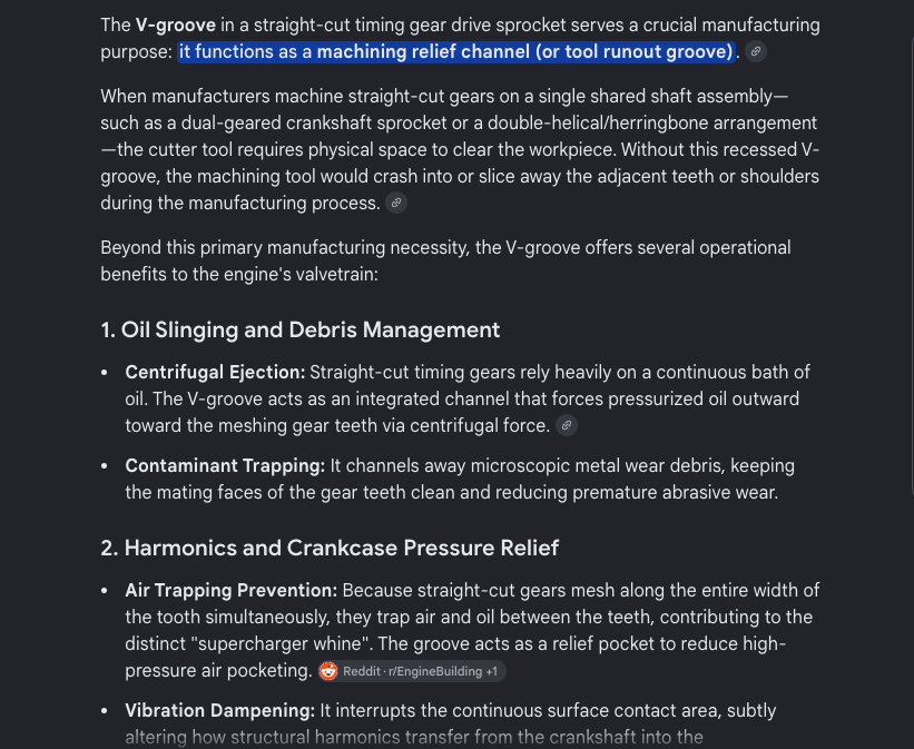
|
|
|
|
|
2 User(s) are reading this topic (2 Guests and 0 Anonymous Users)
0 Members:

|
Lo-Fi Version | Time is now: 22nd September 2026 - 07:38 AM |
Invision Power Board
v9.1.4 © 2026 IPS, Inc.