Home  |  Forums  |  914 Info  |  Blogs
 
914World.com - The fastest growing online 914 community!
 
Porsche, and the Porsche crest are registered trademarks of Dr. Ing. h.c. F. Porsche AG. This site is not affiliated with Porsche in any way.
Its only purpose is to provide an online forum for car enthusiasts. All other trademarks are property of their respective owners.
 

Welcome Guest ( Log In | Register )

 
Reply to this topicStart new topic
> Electrical Plug questions (CIS engine), with a picture.
DougC
post Oct 18 2005, 10:02 AM
Post #1


Senior Member
***

Group: Members
Posts: 949
Joined: 6-July 04
From: Dallas, TX
Member No.: 2,307


Here's a picture of the electrical plugs that are used on the 911 engines with CIS fuel injection. I have to replace 3 of them and want to make sure I get the wireing (+/-) to them correctly. I have to assume that the + and - go to a specific side, right? I mean this thing only plugs in one way and if I cross the polarities I will short out the wiring and it will melt the ground wires (I've already had that happen once). After that mishap I replaced all of the effected wires and now I'm ready to try again. Question is, how to tell which side gets + and which gets - ?

Doug C


Attached image(s)
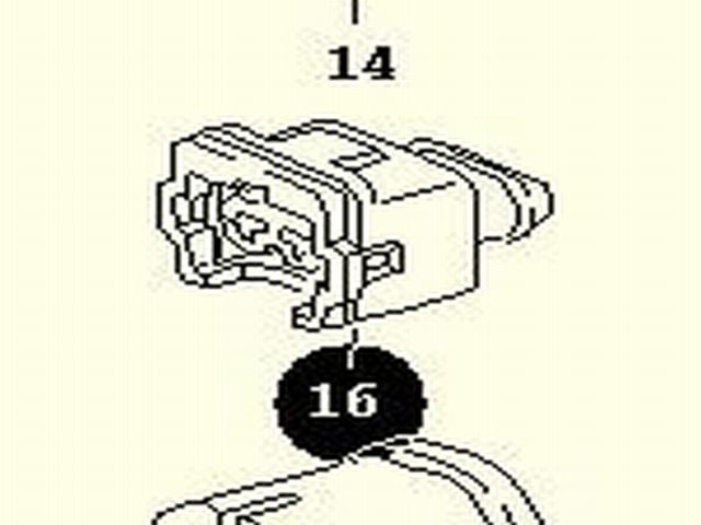
Attached Image
User is offlineProfile CardPM
Go to the top of the page
+Quote Post
lapuwali
post Oct 18 2005, 11:28 AM
Post #2


Not another one!
****

Group: Benefactors
Posts: 4,526
Joined: 1-March 04
From: San Mateo, CA
Member No.: 1,743


QUOTE (DougC @ Oct 18 2005, 08:02 AM)
Here's a picture of the electrical plugs that are used on the 911 engines with CIS fuel injection. I have to replace 3 of them and want to make sure I get the wireing (+/-) to them correctly. I have to assume that the + and - go to a specific side, right? I mean this thing only plugs in one way and if I cross the polarities I will short out the wiring and it will melt the ground wires (I've already had that happen once). After that mishap I replaced all of the effected wires and now I'm ready to try again. Question is, how to tell which side gets + and which gets - ?

Doug C

Wow, that looks astonishingly like an L-Jet injector connector. You sure that's the correct connector?

The WUR is unpolarized, as is the thermo-time switch. The third thing is the airflow meter switch? If so, that's also unpolarized. I don't think you melted the ground wires by crossing them. That's not the usual result in crossing polarities. You melt ground wires by shorting them directly to a power source, which you might do by plugging them into the wrong thing, or by plugging them into something that has an internal short. The WUR heating element is unlikely to be internally shorted, as is the TT switch. There should be almost no current flowing through the airflow meter switch. If you melted those wires, you have the FP relay wired up incorrectly.
User is offlineProfile CardPM
Go to the top of the page
+Quote Post
DougC
post Oct 18 2005, 12:55 PM
Post #3


Senior Member
***

Group: Members
Posts: 949
Joined: 6-July 04
From: Dallas, TX
Member No.: 2,307


You melt ground wires by shorting them directly to a power source, which you might do by plugging them into the wrong thing

Yes, because the wires got attached to the electrical plug backwards the brown ground wire shorted out...that was my thinking anyway. Never the less I can't have anymore wires melting. This was the plug to the Air Meter that I'm talking about. It had a brown wire directly to the "D-" on the alternator and a brown/black wire that I hooked up to the powered spade from the car's original D-jet FI outlet on the relay board. When I did that and cranked the engine those two wires melted (all the way to the alternator). So, I assumed that I crossed those wires when I had replaced this plastic connector that had fallen off. I made sure that ALL effected wires were replaced.

BTW, you are right the plug looks just like a FI electrical plug.

Doug C
User is offlineProfile CardPM
Go to the top of the page
+Quote Post
lapuwali
post Oct 18 2005, 02:29 PM
Post #4


Not another one!
****

Group: Benefactors
Posts: 4,526
Joined: 1-March 04
From: San Mateo, CA
Member No.: 1,743


QUOTE (DougC @ Oct 18 2005, 10:55 AM)
You melt ground wires by shorting them directly to a power source, which you might do by plugging them into the wrong thing

Yes, because the wires got attached to the electrical plug backwards the brown ground wire shorted out...

No, you're misunderstanding me.

The air-meter switch is just a switch. When open, the two wires leading to it are unconnected. When closed, the two wires are connected. If you put +12 on one side of the switch, and ground the other side, then close the switch, you have just shorted +12 to ground. This is bad, and I think it's what you did. It doesn't matter which terminal has +12 and which terminal has ground. Either way, you'll smoke something.

There MUST be a load of some sort between +12 and ground in all electrical circuits. I don't have the schematics for the air-meter wiring on CIS to hand, and my CIS system didn't have this switch. However, since it controls the fuel pump relay, the natural place for it to run is between the ground terminal on the coil part of the relay, and the actual ground. This way, if the air meter switch is open, there's no ground on the relay, so the relay doesn't switch the fuel pump on. With the switch is closed, the relay has a ground, so it switches on the fuel pump.

What I think you did was to connect the fuel pump relay OUTPUT (i.e., normally to the fuel pump) to the air meter switch, and grounded the other end. When the relay switched on, it now routed +12 from the battery straight to through the air-meter switch to ground, running a LOT of current through the wires and the switch. So the problem wasn't that you reversed the wires, it was that you hooked them up incorrectly at the relay end.

If you hook switched +12 (from the ignition switch, usually black wires) to one side of the relay coil (usually terminal 85 on the relay), and hook the other side of the relay coil (usually terminal 86) to the one side of the air-meter switch, then ground to the other side of the air-meter switch, then you'll have the relay coil as the load between +12 and ground (through the closed air-meter switch). The coil will be ON only when the air-meter switch is closed. Terminal 30 on the relay should get unswitched +12 (from the battery, red wires), and terminal 87 should be hooked to the + terminal on the fuel pump. The - terminal on the fuel pump should be connected to ground. Now, when the coil is ON, you'll get battery power to the fuel pump, with the pump itself the load between power and ground. If the air-meter switch opened, then the coil would go OFF, and the fuel pump would go OFF. Terminal 87a on a five-terminal relay would be left unconnected.

If you went to Radio Shack or the like, you could get a generic four or five terminal relay and an inline fuse holder (with a 10 amp fuse). Connect everything up as I mentioned above, and put the fuse between the battery and the relay terminal 30. You'll then have relay switched, fused power to the fuel pump, and the air-meter switch will operate as a safety device, as intended.
User is offlineProfile CardPM
Go to the top of the page
+Quote Post
DougC
post Oct 18 2005, 02:36 PM
Post #5


Senior Member
***

Group: Members
Posts: 949
Joined: 6-July 04
From: Dallas, TX
Member No.: 2,307


James, I'm printing that out as we speak, thanks!

Doug C
User is offlineProfile CardPM
Go to the top of the page
+Quote Post

Reply to this topicStart new topic
1 User(s) are reading this topic (1 Guests and 0 Anonymous Users)
0 Members:


- Lo-Fi Version Time is now: 17th May 2024 - 03:27 PM