|
|
|
Porsche, and the Porsche crest are registered trademarks of Dr. Ing. h.c. F. Porsche AG.
This site is not affiliated with Porsche in any way. Its only purpose is to provide an online forum for car enthusiasts. All other trademarks are property of their respective owners. |
|
|

  |

| groot |
 Nov 19 2005, 09:17 AM Nov 19 2005, 09:17 AM
Post
#41
|
|
Dis member  Group: Members Posts: 894 Joined: 17-December 03 From: Michigan Member No.: 1,444 |
Bigger than I expected... sorry.
Attached thumbnail(s) 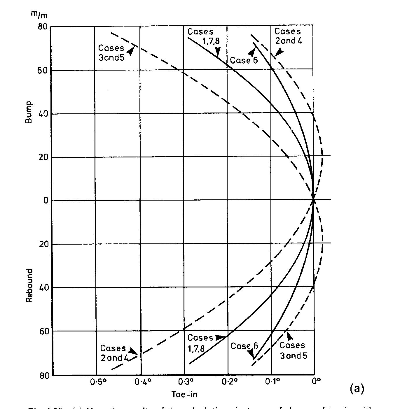
|
   |

 
|
| groot |
Nov 19 2005, 09:17 AM
Post
#42
|
|
Dis member Group: Members Posts: 894 Joined: 17-December 03 From: Michigan Member No.: 1,444 |
Last purdy chart
Attached thumbnail(s) 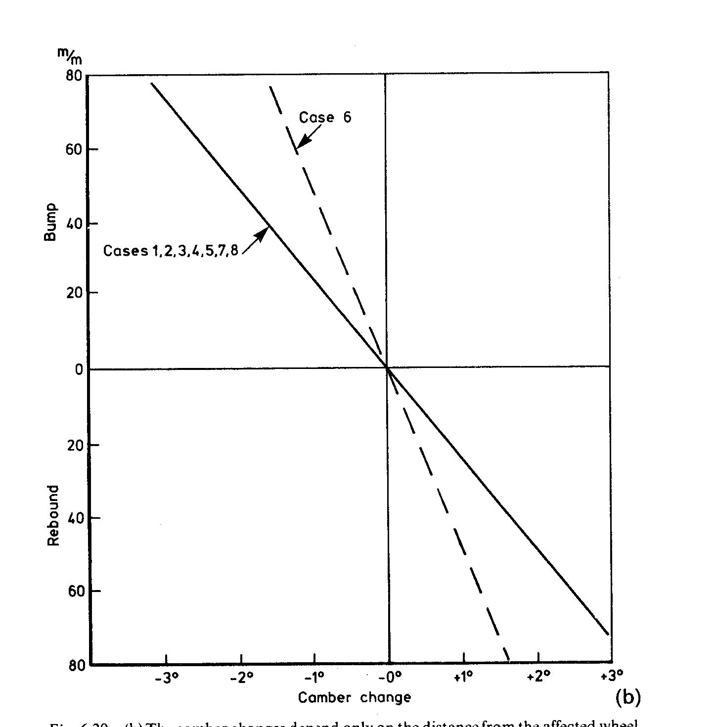
|
|
|
|
| Jeroen |
Nov 19 2005, 10:34 AM
Post
#43
|
|
914 Guru Group: Members Posts: 7,887 Joined: 24-December 02 From: The Netherlands Member No.: 3 Region Association: Europe |
kevin, if you e-mail me the .doc file you tried to post, I'll upload it to the site
just send it to jeroen@berloth.nl |
|
|
|
| groot |
Nov 19 2005, 10:51 AM
Post
#44
|
|
Dis member Group: Members Posts: 894 Joined: 17-December 03 From: Michigan Member No.: 1,444 |
Or I could just post the text.... duh....
Car Suspension and Handling, Second Edition Written by Donald Bastow Penntech Press 6.9 TRAILING AND SEMI-TRAILING ARMS The fundamental difference between trailing and semi-trailing arms is that the axis of the former is at right angles to the car centre line; this implies that there is no change, in end view, of the angle of the wheels with suspension movements. The semi-trailing arm, so far confined to examples where in plan view the axis of oscillation of the arm meets the vertical plane of the wheel axes towards or beyond the other rear wheel, necessarily introduces some swing axle effect. Although it is generally considered that the instantaneous centres are where the arm axis intersects the vertical planes of the rear wheel axes across the car and fore and aft, this is not strictly true. The actual path of any point on the wheel, in side or end elevation, is an ellipse and the instantaneous centre for that part of the ellipse can be found by known methods. The knowledge that roll-steer effects are at a minimum when the semi-trailing arm axis is parallel to the ground is useful but we need to know more. For this we must study how toe-in changes on bump and rebound vary with changes in position of the semi-trailing arm axis, in plan view and in the angle which the axis makes with the ground. A basic case has been chosen in which the semi-trailing arm axis is at road wheel centre height, meets the rear wheel axis of the car at one wheel plane, point 2, and intersects the plane of the wheel whose movements are being studied 400 mm forward of its centre, point 1. Figure 6.19 shows this. An alternative plan position shows the semi -trailing arm axis meeting the rear wheel axis at twice the car track from the wheel being studied, point 2A. Points 3, the wheel centre, and 4, 100 mm away along its axis, are for calculation purposes to obtain the toe-in changes. The heights of points 1 and 2 in Table 6.1 define the axis changes studied, in height and inclination to the ground: rising to the front, dropping to the front, high or low; and parallel to the ground but above or below the original position. The resulting roll centre heights are also shown; they indicate the amount of sideways 'scrub' of the contact patch with bump and rebound movements. Anthony Best Dynamics Ltd. has kindly computed the results and its co-operation is gratefully acknowledged. The results are summarised in Fig. 6.20(a). Figure 6.20(B) shows the camber changes. Fig. 6'20 (a) Here the results of the calculations in terms of change of toe-in with bump and rebound movement are shown. There are effectively no differences between cases 1, 7 and 8 where the axes are parallel to the ground but at different heights. Cases 2 and 4, axes up towards the front but at different heights, are also effectively the same as each other but now favour "bump at the expense of rebound. The converse applies to cases 3 and 5, where rebound is favoured. Case 6, axis parallel to the ground and more nearly so to the rear wheel axis, halves the toe-in changes. Fig. 6.20 (B) The camber changes depend only on the distance from the affected wheel to the intersection of the axis and the vertical transverse plane containing the wheel axes Within the limits studied, i.e. axis height::l: 20 mm parallel to the ground, and a height change of 20 mm in sloping axes, nose high and nose low, and bump and rebound movements each of 75 mm, axis height does not affect the results (to two significant figures). The nose high axis position favours bump movements, and vice versa. Camber changes depend only on the distance from the studied wheel to the intersection of the semi-trailing arm axis, point 2, with the transverse vertical plane containing the undefIected rear wheel axes. From the trends within the range studied, we see that a sufficiently large nose-high axis angle wilI give toe-out on bump and toe-in on rebound; and again vice versa. If the distance between wheel arches is important it must be remembered that the introduction of any swing axle effect has to be accompanied by an increase in the track to maintain that distance between wheel arches. |
|
|
|
| Brett W |
Nov 26 2005, 08:55 PM
Post
#45
|
|
Advanced Member Group: Members Posts: 2,856 Joined: 17-September 03 From: huntsville, al Member No.: 1,169 Region Association: None |
That is some impressive math and I am sure the results are correct for the input you used, but the inputs are wrong. The trailing arm pivots in a different axis. You also don't account for anything other than a single plane view. The semi trailing arm axis is located in a 3D plane. It will change toe because the trailing arm moves in an arc in two planes. Does the suspension based on your numbers gain camber? If so how can it change toe?
|
|
|
|
| ChrisFoley |
Nov 27 2005, 07:44 AM
Post
#46
|
|
I am Tangerine Racing Group: Members Posts: 7,922 Joined: 29-January 03 From: Bolton, CT Member No.: 209 Region Association: None |
I don't understand what the 3d surface plots represent since you haven't labeled the axes. Also, since the units on each axis change from graph to graph, any trend is distorted.
I think it would be more meaningful to plot camber and toe independently, as a function of trailing arm rotation using 2d coordinates. By plotting them simultaneously on one graph their interdependence would be apparent. |
|
|
|
| Brett W |
Nov 27 2005, 11:13 AM
Post
#47
|
|
Advanced Member Group: Members Posts: 2,856 Joined: 17-September 03 From: huntsville, al Member No.: 1,169 Region Association: None |
I agree seperate them so that they aer more easily read and a 2D curve will suffice for each one.
Yes you will not see large changes in either, because that just doesn't happen. The semi trailing arm does not make big changes, but the little changes will make all kinds of problems in a race situation. When your suspension travel is limited to 1-2 inches in both bump and droop, small variations will become big problems. When your chassis is setup to take advantage of 20K lb/degree of twist, and your suspension is setup so that there is no uncontrolled movement, any suspension movement that is not controlled keeps you out of the winners circle. When your chassis is so stiff that your race car setup changes each time you change tires you know you have done it right. |
|
|
|
| ChrisFoley |
Dec 5 2005, 08:30 AM
Post
#48
|
|
I am Tangerine Racing Group: Members Posts: 7,922 Joined: 29-January 03 From: Bolton, CT Member No.: 209 Region Association: None |
Whats the x axis represent?
Can't you convert your graph y axis labels to degrees? |
|
|
|
|
1 User(s) are reading this topic (1 Guests and 0 Anonymous Users)
0 Members:

|
Lo-Fi Version | Time is now: 4th May 2024 - 02:06 PM |
Invision Power Board
v9.1.4 © 2024 IPS, Inc.