|
|
|
Porsche, and the Porsche crest are registered trademarks of Dr. Ing. h.c. F. Porsche AG.
This site is not affiliated with Porsche in any way. Its only purpose is to provide an online forum for car enthusiasts. All other trademarks are property of their respective owners. |
|
|

  |

| nick mironov |
 Nov 18 2005, 09:47 PM Nov 18 2005, 09:47 PM
Post
#1
|
|
nickm  Group: Members Posts: 204 Joined: 12-June 05 From: San Francisco, CA Member No.: 4,264 |
Does anyone know what the proper interface should be between the crankshaft pilot bearing and the transmission input shaft bearing surface?
I have a Chevy 283 with a Renegade adapter plate and a KEP pilot bushing/bearing (provided by Renegade)in the end of the crankshaft. The bushing/bearing sticks out about 1/16” beyond the crankshaft face, which ends up just behind the flywheel surface and consequently just clears the clutch disk. I think that this setup is correct. When I mate the transaxle top the engine, the transmission input shaft does not penetrate the pilot bearing all the way – only about 1/2 to 2/3 leaving about 1/2 to1/3 on the outside of the bearing. This does not seem correct, as I would have expected complete or nearly complete contact of the shaft bearing surface with the pilot bearing. I have contacted Renegade, but they could not say what the proper setup should be. Does anyone know what the correct setup should be, and if complete contact is normal, why mine is so far off? Please see pictures below: Attached thumbnail(s) 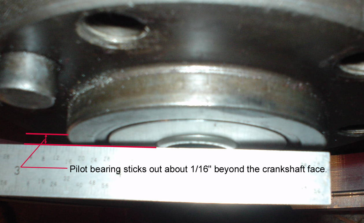
|
   |

 
|
| nick mironov |
Nov 18 2005, 09:50 PM
Post
#2
|
|
nickm Group: Members Posts: 204 Joined: 12-June 05 From: San Francisco, CA Member No.: 4,264 |
Picture 2:
This picture shows the transaxle mated to the engine, but without the pilot bushing/bearing in place. You need to imagine it is there (see picture above). I thought of this only after I took it apart and then it was too late. Attached image(s) 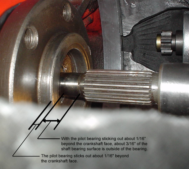
|
|
|
|
| Brad Roberts |
Nov 18 2005, 10:40 PM
Post
#3
|
|
914 Freak! Group: Members Posts: 19,148 Joined: 23-December 02 Member No.: 8 Region Association: None |
You are splitting hairs. Bolt it together. If you are worried about that 1/16th.. push the actual bearing into the billet holder farther. I have yet to see the depth setting for a factory bearing in the factory flywheel. Not saying it isnt in a manual somewhere.. but I havent seen it.
Just wait until you see some of the other tolerances in the kit. B |
|
|
|
| bondo |
Nov 18 2005, 11:02 PM
Post
#4
|
||
|
Practicing my perpendicular parking Group: Members Posts: 4,277 Joined: 19-April 03 From: Los Osos, CA Member No.: 587 Region Association: Central California |
That would make the problem he's describing worse. Perhaps the pilot bearing is set up for an adapter plate of a different thickness. Is the bearing tight enough that you could just not press it all the way in? |
||
|
|
|
||
| neo914-6 |
Nov 19 2005, 12:30 AM
Post
#5
|
|
neo life Group: Members Posts: 5,086 Joined: 16-January 03 From: Willow Glen (San Jose) Member No.: 159 |
Nick,
I presume you have access to RH login site. The RH pilot bushing is steel and KEP is aluminum. This tells it all... Attached thumbnail(s) 
|
|
|
|
| Dr. Roger |
Nov 19 2005, 01:10 AM
Post
#6
|
|
A bat out of hell. Group: Members Posts: 3,944 Joined: 31-January 05 From: Hercules, California Member No.: 3,533 Region Association: Northern California |
i had the same question/concern and contacted Renegtade/Scott.
i was told that was normal. i have had no problems. that bearing is the least of your worries.... LOL (IMG:http://www.914world.com/bbs2/html/emoticons/laugh.gif) (IMG:http://www.914world.com/bbs2/html/emoticons/huh.gif) |
|
|
|
| nick mironov |
Nov 19 2005, 11:17 AM
Post
#7
|
|
nickm Group: Members Posts: 204 Joined: 12-June 05 From: San Francisco, CA Member No.: 4,264 |
Can anyone take a picture of their setup either through the flywheel inspection opening or through the clutch fork opening so I can see your arrangment / alighment?
The potential problem is not the 1/16" protrusion of the bearing (this is what is expected and is implied to be normal by the Renegade instructions - they do not actually say how much it is to protrude form the crankshaft end), but the fact that only 1/2 to 2/3 of the pilot bearing is loaded and all of the load will be at one end of the bearing. This could cause premature, and catastrophic failure. Pusing the bearing in further (if even possible) would make the problem worse. Pulling it out a little, will have it interfere with the clutch disk. The slight protrusion is correct. It seems that the adapter plate needs to be thinner allowing the input shaft to penetrate deeper into the bearing, but that could screw up all sorts of other alignmments - flywheel clearnace to housing, starter gear to flywheel gear alignment, clutch fork position, etc. A picture would be great... |
|
|
|
| nick mironov |
Nov 23 2005, 12:29 PM
Post
#8
|
|
nickm Group: Members Posts: 204 Joined: 12-June 05 From: San Francisco, CA Member No.: 4,264 |
I believe that I have resolved the issue. When I originally tested the condition, I only hand-tightened the TX/engine mounting nuts/bolts. I tried it again and this time wrench-tightened the nuts/bots and that pulled the transmission closer to the engine and made for a greater penetration of the transmission input shaft into the pilot bearing. I am getting about 85% penetration now which appears to be correct. I verified that the engine crankshaft extends from the end of the engine 0.70" (GM spec) and that the adapter plate thickness at the transmisssion mount surface is 0.66" (per KEP). It appears that everything is the way it should be.
|
|
|
|
|
1 User(s) are reading this topic (1 Guests and 0 Anonymous Users)
0 Members:

|
Lo-Fi Version | Time is now: 7th May 2024 - 05:48 PM |
Invision Power Board
v9.1.4 © 2024 IPS, Inc.