|
|
|
Porsche, and the Porsche crest are registered trademarks of Dr. Ing. h.c. F. Porsche AG.
This site is not affiliated with Porsche in any way. Its only purpose is to provide an online forum for car enthusiasts. All other trademarks are property of their respective owners. |
|
|

  |

| marks914 |
 Dec 31 2005, 12:53 PM Dec 31 2005, 12:53 PM
Post
#1
|
|
Senior Member  Group: Members Posts: 845 Joined: 9-October 04 From: the motor city Member No.: 2,912 Region Association: None |
I am currently installing my new set of B/M longitudinal clamshells. Any suggestions on removing the jack post/plates? I have the pass side done, I had to do some patching so I was not too careful in their removal. The driver side is solid, so I would like to remove it surgically. I have drilled out the spot welds I can reach, started prying and came in for lunch. I will post some pics of the progress this week
Thanks Mark |
   |

 
|
| r_towle |
Dec 31 2005, 01:08 PM
Post
#2
|
|
Custom Member Group: Members Posts: 24,579 Joined: 9-January 03 From: Taxachusetts Member No.: 124 Region Association: North East States |
Hi,
to answer your question...you need to drill out the spot weld, and then use either an air powered chisel of a hand cold chisel to get the welds you cannot get to with the drill... Basically, get the bottom and sides doen, then bend it up and get under the other ones with the chisel... Please Please show pics of the install process. I have never seen pics of the elusive Brad Mayeur kit being installed and I would really like to see the process, at least hold it up and show how it fits and what it looks like... I have heard lots of info on it, just never saw the product of I have never seen how it fits... Do you go over the outer long, or do you remove that? I need to do this and I might either go with the BM kit or the outer clamshell kit that restoration design sells... to me it depends upon which one is easier to install. Rich |
|
|
|
| Mueller |
Dec 31 2005, 01:09 PM
Post
#3
|
|
914 Freak! Group: Members Posts: 17,146 Joined: 4-January 03 From: Antioch, CA Member No.: 87 Region Association: None |
you are on the right track....drilling out the spot welds and removing parts in layers is about the only way....
try tapping with a hammer and prying the parts, you should be able to see where the hidden spot welds are.... good luck (IMG:http://www.914world.com/bbs2/html/emoticons/smash.gif) (IMG:http://www.914world.com/bbs2/html/emoticons/welder.gif) |
|
|
|
| J P Stein |
Dec 31 2005, 01:25 PM
Post
#4
|
|
Irrelevant old fart Group: Members Posts: 8,797 Joined: 30-December 02 From: Vancouver, WA Member No.: 45 Region Association: None |
A major weapon in my tool arsenal is (are) die grinders (air & electric) & carbide rotary files. You can get into tight spots & do fine work or cut the car in half...as the mood suits you. (IMG:http://www.914world.com/bbs2/html/emoticons/biggrin.gif)
Care must be taken for flying FOD. I no longer have jack pads. |
|
|
|
| joea9146 |
Dec 31 2005, 07:05 PM
Post
#5
|
|
Senior Member Group: Members Posts: 663 Joined: 10-February 03 From: Denver, NC Member No.: 283 Region Association: None |
I removed mine.... And JP turned me onto the Carbide Rotary files and they work Great
|
|
|
|
| marks914 |
Dec 31 2005, 07:28 PM
Post
#6
|
|
Senior Member Group: Members Posts: 845 Joined: 9-October 04 From: the motor city Member No.: 2,912 Region Association: None |
Thanks, Thats what I've been doing,
Here are some progress pics>>> Half of the kit, the clamshells fit directly over the longs and part of the suspension console. So far it hasn't been too bad. I will write up a complete step by step later. Attached image(s) 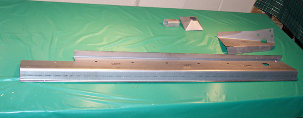
|
|
|
|
| marks914 |
Dec 31 2005, 07:29 PM
Post
#7
|
|
Senior Member Group: Members Posts: 845 Joined: 9-October 04 From: the motor city Member No.: 2,912 Region Association: None |
Here you can see the section, how it wraps around the longs and supports the step plate, pretty clever. The kit is 3/32 steel, 38 LBS
Attached image(s) 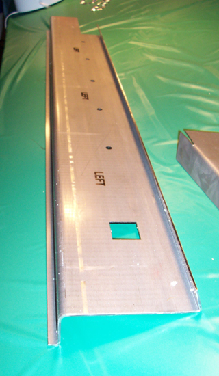
|
|
|
|
| marks914 |
Dec 31 2005, 07:31 PM
Post
#8
|
|
Senior Member Group: Members Posts: 845 Joined: 9-October 04 From: the motor city Member No.: 2,912 Region Association: None |
The pass side was a bit rusty. I patched the holes before I put the clamshell over it...
Attached image(s) 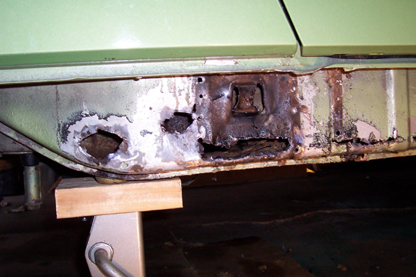
|
|
|
|
| marks914 |
Dec 31 2005, 07:32 PM
Post
#9
|
|
Senior Member Group: Members Posts: 845 Joined: 9-October 04 From: the motor city Member No.: 2,912 Region Association: None |
Here is the right side installed, don't laugh at my welds, not very pretty, but they are strong
Attached image(s) 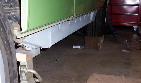
|
|
|
|
| r_towle |
Dec 31 2005, 07:32 PM
Post
#10
|
|
Custom Member Group: Members Posts: 24,579 Joined: 9-January 03 From: Taxachusetts Member No.: 124 Region Association: North East States |
is it meant to be spot welded? or seam welded?
Rich |
|
|
|
| marks914 |
Dec 31 2005, 07:33 PM
Post
#11
|
|
Senior Member Group: Members Posts: 845 Joined: 9-October 04 From: the motor city Member No.: 2,912 Region Association: None |
I had some rust under the boxed section at the front of the long, I cut it out and re-created it.
Attached image(s) 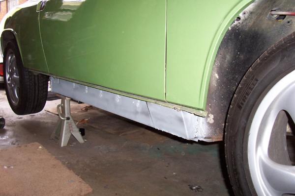
|
|
|
|
| marks914 |
Dec 31 2005, 07:37 PM
Post
#12
|
||
|
Senior Member Group: Members Posts: 845 Joined: 9-October 04 From: the motor city Member No.: 2,912 Region Association: None |
You plug weld through the holes in the clamshell onto the ribs and weld along the seam along the bottom. For more details go here: http://www.pelicanparts.com/techarticles/9...gitude_repl.htm Mark |
||
|
|
|
||
| marks914 |
Jan 1 2006, 12:49 PM
Post
#13
|
|
Senior Member Group: Members Posts: 845 Joined: 9-October 04 From: the motor city Member No.: 2,912 Region Association: None |
Driver side went much better getting plates off, no rust, HOORAY!
|
|
|
|
| SUSPENDED |
Jan 1 2006, 12:56 PM
Post
#14
|
|
Newbie Group: Members Posts: 4 Joined: 31-December 05 From: South Bend, IN Member No.: 5,341 |
I've has this kit laying around for a while and was always wondering how you make sure the chassis straight before you weld. using jacks part makes sense but how do you know your straight? this is my first post by the way so, hello to all!
|
|
|
|
| Mueller |
Jan 1 2006, 01:10 PM
Post
#15
|
||
|
914 Freak! Group: Members Posts: 17,146 Joined: 4-January 03 From: Antioch, CA Member No.: 87 Region Association: None |
on the top of the page of the page there is a 914 Info section, dimensions should be listed for lining up the car....however, you might just be better off ensureing that the door gaps remain somewhat consistant and go from there. |
||
|
|
|
||
| J P Stein |
Jan 1 2006, 01:15 PM
Post
#16
|
|
Irrelevant old fart Group: Members Posts: 8,797 Joined: 30-December 02 From: Vancouver, WA Member No.: 45 Region Association: None |
Could you show the rear section a bit more clearly....where the long turns upward.
I like that set-up. No fishing lures here....near as I can tell. I would have done more plug welds...prolly double or triple the amount on the verticle face and maybe on the bottom....I can't see that area in your pics. How thick is it? |
|
|
|
| rick 918-S |
Jan 1 2006, 01:17 PM
Post
#17
|
||
|
Hey nice rack! -Celette Group: Members Posts: 20,464 Joined: 30-December 02 From: Now in Superior WI Member No.: 43 Region Association: Northstar Region |
Welcome! (IMG:http://www.914world.com/bbs2/html/emoticons/wavey.gif) Someone will post the chassis diagram link soon I'm sure. I don't know where it is. But someplace, either here or the Bird Board. |
||
|
|
|
||
| SUSPENDED |
Jan 1 2006, 01:20 PM
Post
#18
|
|
Newbie Group: Members Posts: 4 Joined: 31-December 05 From: South Bend, IN Member No.: 5,341 |
thanks, damn you guys move fast in here! looking forward to talking with you folks.
|
|
|
|
| marks914 |
Jan 1 2006, 02:12 PM
Post
#19
|
||
|
Senior Member Group: Members Posts: 845 Joined: 9-October 04 From: the motor city Member No.: 2,912 Region Association: None |
That's all the plug welds you can get, the holes are on the ribs of the long, the farther down you go, the poorer the gap. The lower section is also welded onto the drop flange. and the upper to the sill step plate. Its 3/32 thick, 38 lbs Mark I will snap a closeup of the rear part later. |
||
|
|
|
||
| Aaron Cox |
Jan 1 2006, 02:26 PM
Post
#20
|
|
Professional Lawn Dart Group: Retired Admin Posts: 24,541 Joined: 1-February 03 From: OC Member No.: 219 Region Association: Southern California |
these plus an engman inner long kit would make for a super strong long no?
|
|
|
|
|
1 User(s) are reading this topic (1 Guests and 0 Anonymous Users)
0 Members:

|
Lo-Fi Version | Time is now: 23rd May 2024 - 02:45 PM |
Invision Power Board
v9.1.4 © 2024 IPS, Inc.