|
|
|
Porsche, and the Porsche crest are registered trademarks of Dr. Ing. h.c. F. Porsche AG.
This site is not affiliated with Porsche in any way. Its only purpose is to provide an online forum for car enthusiasts. All other trademarks are property of their respective owners. |
|
|


| yarin |
 Jan 28 2006, 01:36 AM Jan 28 2006, 01:36 AM
Post
#41
|
|
'14-X'in FOOL  Group: Members Posts: 988 Joined: 13-May 03 From: Guttenberg, NJ Member No.: 693 Region Association: North East States |
Tonight I have completed building the main board for my MS II V.3.0 system. Thanks to those that have helped out. Once i'm all finished I will definitely post a complete "How To MegaSquirt a 914" website with pics and step by step. So far i'm still at the desk level. I've got 2.0 injection parts on the way.
I'll be using the following: stock injectors GM air temp sensor stock fuel pump summit racing manifold referenced fuel pressure regulator stock injectors (i think 2.0s are on the way) stock plenum / runners stock CHT MS Relay Board Innovative WB02 High Current ignition driver Stock dizzy with pertronix (hall sensor) Stock Bosch Blue Coil PWM Low impedence injector driver (no resistors) Stock Cold start Valve (plan so far) Stock throttle body with some junkyard TPS Here is a pic of my board, took me a few hours a night every night this week. I took my time, double checked everything. So far so good! I don't expect to have the system in the car for at least another month. I'm converting from carbs so I want to install steel fuel lines and clean some stuff up. I'll be sure to post progress in the forums. (IMG:http://www.914world.com/bbs2/html/emoticons/smilie_pokal.gif) Attached image(s) 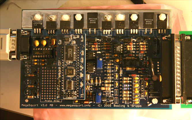
|
   |

 
|
Posts in this topic
 yarin Megasquirt Progress Jan 28 2006, 01:36 AM
 yarin my converted workshop... temporary of course Jan 28 2006, 01:39 AM yarin shot of my soldering skills at the beginning. Jan 28 2006, 01:40 AM dinomium Yes, the injetors are the pretty green ones! B... Jan 28 2006, 01:41 AM Tom Perso Looks familar... http://www.... Jan 28 2006, 06:51 AM Mueller I highly recommend testing the injectors "before" ... Jan 28 2006, 10:08 AM yarin I was planning on sending my injectors out to RC E... Jan 28 2006, 10:27 AM crash914 Yarin,
You will like the version 3 system...
I ... Jan 29 2006, 10:12 AM Tom Perso ... Jan 29 2006, 11:30 AM yarin I ordered my stuff from http://www.diyautotune.com... Jan 29 2006, 02:31 PM crash914 msII drop in chip is available...you can buy on li... Jan 30 2006, 06:35 AM alpha434 Bump.
Megasquirt? Jan 30 2006, 11:21 PM Mueller ... Jan 31 2006, 12:23 AM alpha434 ok. So... Outside of price. What kicks it's as... Jan 31 2006, 12:28 AM Mueller ... Jan 31 2006, 12:58 AM alpha434 Ahhhhhh. I see. So nothing. Hmmmm....
Replace my ... Jan 31 2006, 01:04 AM Mueller ... Jan 31 2006, 01:13 AM alpha434 Alright. The next objective for my top secret proj... Jan 31 2006, 01:19 AM agrump Yarin,
I have a similar setup to what you are pla... Jan 31 2006, 07:36 AM yarin Hey Dean,
Someone on MSEFI forums used a 1.3K pul... Jan 31 2006, 09:28 PM DNHunt One piece of advice. Plan your cable from the ECU ... Feb 1 2006, 08:21 AM yarin Dave,
I will be sure to strain relief both sides ... Feb 1 2006, 08:33 AM DNHunt As a guideline I have a 180 degree turn a the rela... Feb 1 2006, 08:42 AM bd1308 BNC connectors!!!?!!?!?... Feb 1 2006, 08:45 AM yarin I bought the 12' cable from DIYautotune.
The... Feb 1 2006, 08:48 AM agrump Yarin,
I am using a pertronix. I did not use the... Feb 1 2006, 08:55 AM DNHunt Also on the injectors and fuel pressure. I believe... Feb 1 2006, 08:57 AM bd1308 If i do this on my 1.7, is there someone that coul... Feb 1 2006, 08:59 AM sgomes LEMO http://www.914world.co... Feb 1 2006, 09:02 AM yarin Check these out, FCI D-sub Mixed Power DW series
... Feb 1 2006, 09:09 AM DNHunt Britt
There is plenty of support online. Meuller... Feb 1 2006, 09:13 AM yarin Feb 1 2006, 10:56 AM yarin Feb 1 2006, 11:02 AM lapuwali IMHO, Dave's experience with solder cup DB con... Feb 1 2006, 12:26 PM yarin James,
Thanks for you feedback. I will run the in... Feb 1 2006, 02:51 PM jhadler The stock D-jet regulator is pretty good. You say ... Feb 1 2006, 03:06 PM yarin Josh, Yes rising rate. Or in our case when the ma... Feb 1 2006, 03:22 PM lapuwali You can modify the stock D-Jet FPR to reference it... Feb 1 2006, 03:25 PM lapuwali Feb 1 2006, 03:41 PM DNHunt I understand the rising rate FPR but, I haven... Feb 1 2006, 04:48 PM lapuwali Feb 1 2006, 05:13 PM agrump Feb 1 2006, 06:56 PM yarin Do a search for closed loop idle on MSEFI.com foru... Feb 1 2006, 07:01 PM lapuwali Case in point: this guy is devoting a third of his... Feb 1 2006, 07:09 PM Jeff Nelson I think there might be some confusion as to what a... Feb 1 2006, 07:15 PM lapuwali
yarin my converted workshop... temporary of course Jan 28 2006, 01:39 AM yarin shot of my soldering skills at the beginning. Jan 28 2006, 01:40 AM dinomium Yes, the injetors are the pretty green ones! B... Jan 28 2006, 01:41 AM Tom Perso Looks familar... http://www.... Jan 28 2006, 06:51 AM Mueller I highly recommend testing the injectors "before" ... Jan 28 2006, 10:08 AM yarin I was planning on sending my injectors out to RC E... Jan 28 2006, 10:27 AM crash914 Yarin,
You will like the version 3 system...
I ... Jan 29 2006, 10:12 AM Tom Perso ... Jan 29 2006, 11:30 AM yarin I ordered my stuff from http://www.diyautotune.com... Jan 29 2006, 02:31 PM crash914 msII drop in chip is available...you can buy on li... Jan 30 2006, 06:35 AM alpha434 Bump.
Megasquirt? Jan 30 2006, 11:21 PM Mueller ... Jan 31 2006, 12:23 AM alpha434 ok. So... Outside of price. What kicks it's as... Jan 31 2006, 12:28 AM Mueller ... Jan 31 2006, 12:58 AM alpha434 Ahhhhhh. I see. So nothing. Hmmmm....
Replace my ... Jan 31 2006, 01:04 AM Mueller ... Jan 31 2006, 01:13 AM alpha434 Alright. The next objective for my top secret proj... Jan 31 2006, 01:19 AM agrump Yarin,
I have a similar setup to what you are pla... Jan 31 2006, 07:36 AM yarin Hey Dean,
Someone on MSEFI forums used a 1.3K pul... Jan 31 2006, 09:28 PM DNHunt One piece of advice. Plan your cable from the ECU ... Feb 1 2006, 08:21 AM yarin Dave,
I will be sure to strain relief both sides ... Feb 1 2006, 08:33 AM DNHunt As a guideline I have a 180 degree turn a the rela... Feb 1 2006, 08:42 AM bd1308 BNC connectors!!!?!!?!?... Feb 1 2006, 08:45 AM yarin I bought the 12' cable from DIYautotune.
The... Feb 1 2006, 08:48 AM agrump Yarin,
I am using a pertronix. I did not use the... Feb 1 2006, 08:55 AM DNHunt Also on the injectors and fuel pressure. I believe... Feb 1 2006, 08:57 AM bd1308 If i do this on my 1.7, is there someone that coul... Feb 1 2006, 08:59 AM sgomes LEMO http://www.914world.co... Feb 1 2006, 09:02 AM yarin Check these out, FCI D-sub Mixed Power DW series
... Feb 1 2006, 09:09 AM DNHunt Britt
There is plenty of support online. Meuller... Feb 1 2006, 09:13 AM yarin Feb 1 2006, 10:56 AM yarin Feb 1 2006, 11:02 AM lapuwali IMHO, Dave's experience with solder cup DB con... Feb 1 2006, 12:26 PM yarin James,
Thanks for you feedback. I will run the in... Feb 1 2006, 02:51 PM jhadler The stock D-jet regulator is pretty good. You say ... Feb 1 2006, 03:06 PM yarin Josh, Yes rising rate. Or in our case when the ma... Feb 1 2006, 03:22 PM lapuwali You can modify the stock D-Jet FPR to reference it... Feb 1 2006, 03:25 PM lapuwali Feb 1 2006, 03:41 PM DNHunt I understand the rising rate FPR but, I haven... Feb 1 2006, 04:48 PM lapuwali Feb 1 2006, 05:13 PM agrump Feb 1 2006, 06:56 PM yarin Do a search for closed loop idle on MSEFI.com foru... Feb 1 2006, 07:01 PM lapuwali Case in point: this guy is devoting a third of his... Feb 1 2006, 07:09 PM Jeff Nelson I think there might be some confusion as to what a... Feb 1 2006, 07:15 PM lapuwali 
  |
1 User(s) are reading this topic (1 Guests and 0 Anonymous Users)
0 Members:

|
Lo-Fi Version | Time is now: 2nd April 2026 - 03:18 PM |
Invision Power Board
v9.1.4 © 2026 IPS, Inc.
| All rights reserved 914World.com © since 2002 |
|
914World.com is the fastest growing online 914 community! We have it all, classifieds, events, forums, vendors, parts, autocross, racing, technical articles, events calendar, newsletter, restoration, gallery, archives, history and more for your Porsche 914 ... |