|
|
|
Porsche, and the Porsche crest are registered trademarks of Dr. Ing. h.c. F. Porsche AG.
This site is not affiliated with Porsche in any way. Its only purpose is to provide an online forum for car enthusiasts. All other trademarks are property of their respective owners. |
|
|

  |

| yarin |
 Mar 28 2006, 09:37 PM Mar 28 2006, 09:37 PM
Post
#1
|
|
'14-X'in FOOL  Group: Members Posts: 988 Joined: 13-May 03 From: Guttenberg, NJ Member No.: 693 Region Association: North East States |
I Was about to dig up my old thread from two months ago... but I felt some of these pics deserve there own thread.
I'm really moving along on my upgrade from carbs to MS. I should be able to power up the system this weekend and crank it the following weekend. I chose a rather different approach to my install, a combination of logic, simplicity and durability. Please give me your input. For those who aren't familiar with MS go to www.megasquirt.info and www.msefi.com (forums). I bought all of my Megasquirt parts from DIYautotune.com. Excellent vendor, i suggest doing business with them for anything. What's left: finish db-37 connector connect all wires in relay box mount intake plenum, connect DIY PVC intake install gas tank checked double check and triple check all fuel connections and wiring configure MS crank!! Here are pics: Attached image(s) 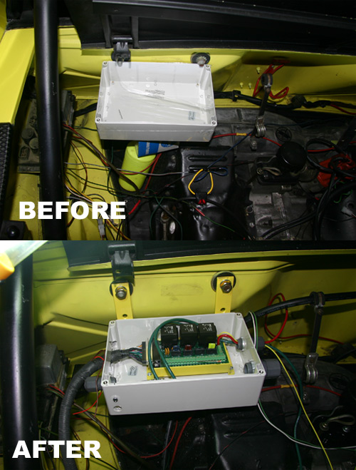
|
   |

 
|
| yarin |
Mar 28 2006, 09:38 PM
Post
#2
|
|
'14-X'in FOOL Group: Members Posts: 988 Joined: 13-May 03 From: Guttenberg, NJ Member No.: 693 Region Association: North East States |
aint it purty? (IMG:http://www.914world.com/bbs2/html/emoticons/aktion035.gif)
Attached image(s) 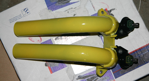
|
|
|
|
| yarin |
Mar 28 2006, 09:39 PM
Post
#3
|
|
'14-X'in FOOL Group: Members Posts: 988 Joined: 13-May 03 From: Guttenberg, NJ Member No.: 693 Region Association: North East States |
(IMG:http://www.914world.com/bbs2/html/emoticons/laugh.gif) i like it
Ok i'll admit it.. the injector connectors do need the outer plastic housing trimmed to fit properly on the injectors. not plug and play, but it should be a solid connection once some material is removed. All parts sand blasted and powder coated by ME. (IMG:http://www.914world.com/bbs2/html/emoticons/mueba.gif) Attached image(s) 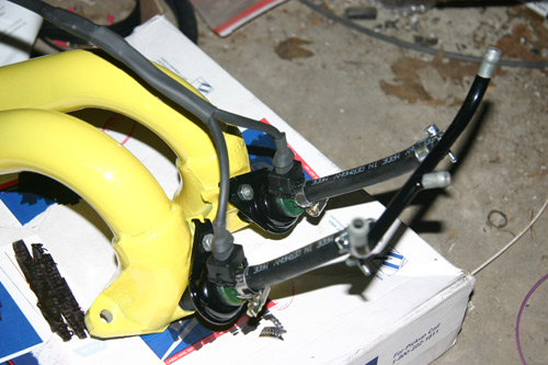
|
|
|
|
| yarin |
Mar 28 2006, 09:40 PM
Post
#4
|
|
'14-X'in FOOL Group: Members Posts: 988 Joined: 13-May 03 From: Guttenberg, NJ Member No.: 693 Region Association: North East States |
db-37, i went the crimp route instead of the kit solder cup.
Attached image(s) 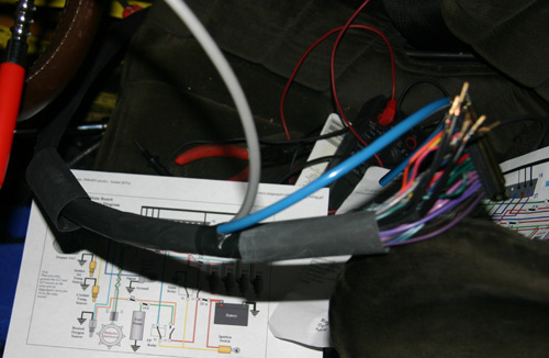
|
|
|
|
| yarin |
Mar 28 2006, 09:41 PM
Post
#5
|
|
'14-X'in FOOL Group: Members Posts: 988 Joined: 13-May 03 From: Guttenberg, NJ Member No.: 693 Region Association: North East States |
Rumor has it the DB37 connections are the biggest design issue with megasquirt.
Attached image(s) 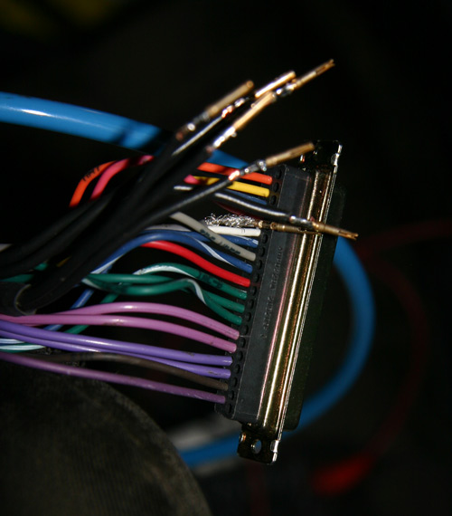
|
|
|
|
| yarin |
Mar 28 2006, 09:41 PM
Post
#6
|
|
'14-X'in FOOL Group: Members Posts: 988 Joined: 13-May 03 From: Guttenberg, NJ Member No.: 693 Region Association: North East States |
soon to be off jacks.
Attached image(s) 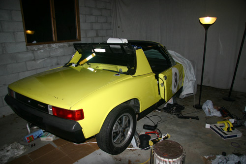
|
|
|
|
| newto914s |
Mar 28 2006, 11:35 PM
Post
#7
|
|
Senior Member Group: Members Posts: 561 Joined: 16-February 04 From: Thornton, CO Member No.: 1,663 |
way to go yarin (IMG:http://www.914world.com/bbs2/html/emoticons/smilie_pokal.gif)
I like the look of the powder coated fuel rails. Very slick! Samson |
|
|
|
| fiid |
Mar 29 2006, 12:37 AM
Post
#8
|
|
Turbo Megasquirted Subaru Member Group: Members Posts: 2,827 Joined: 7-April 03 From: San Francisco, CA Member No.: 530 Region Association: Northern California |
Looks clean - very nice work... good job!
|
|
|
|
| brokenmoped |
Mar 29 2006, 12:46 AM
Post
#9
|
|
Member Group: Members Posts: 143 Joined: 27-May 05 From: Mission Viejo, CA Member No.: 4,152 |
What happened to the panasports?
|
|
|
|
| mightyohm |
Mar 29 2006, 03:22 AM
Post
#10
|
|
Advanced Member Group: Benefactors Posts: 2,277 Joined: 16-January 03 From: Seattle, WA Member No.: 162 Region Association: Pacific Northwest |
What gauge wire is used for the DB-37 connections? Is that a kit?
And I can't tell from the photo, but are the crimp terminals actually soldered to the wire? I am building my own Megasquirt system as well. I am not using the relay board approach however, my harness will go straight into the ECU box in the car. |
|
|
|
| yarin |
Mar 29 2006, 05:40 AM
Post
#11
|
||
|
'14-X'in FOOL Group: Members Posts: 988 Joined: 13-May 03 From: Guttenberg, NJ Member No.: 693 Region Association: North East States |
I have two sets of panasports with race tires. I bought a crappy street set to drive around the street for dirt cheap. Don't worry, i'm holding onto those panasports with my life (IMG:http://www.914world.com/bbs2/html/emoticons/biggrin.gif) |
||
|
|
|
||
| yarin |
Mar 29 2006, 05:46 AM
Post
#12
|
||
|
'14-X'in FOOL Group: Members Posts: 988 Joined: 13-May 03 From: Guttenberg, NJ Member No.: 693 Region Association: North East States |
I bought the relay cable kit from DIYautotune. I would highly recommend that everyone building a MS kit does the same, even if you aren't using a relay box. They kit comes with one end terminated and the parts to solder a db-37 connector on. In your case just chuck the db-37 parts, they dont cost anything anyway. The wiring in the DIYautotune harness is automotive grade 20AWG with the exception of the grounds and injector wires which are 14AWG. The ignition wire is shielded with a 20AWG core. The 14AWG wires breakout into 20AWG at the DB37 end. Internal to the cable there is some sort of junction to go from 1 14ga to 3 20ga in the case of the grounds. I did the same on the side that I terminated. The photo you are looking at is the side that I crimped. The wire I used for the grounds and injector wires is 18ga, probably a little too heavy for the crimp. So I added a touch of solder as a safety. If I had to do it again I would have used standard 20ga wire. Yes I had proper tooling to crimp these connectors on. It aint cheap to purchase. |
||
|
|
|
||
| mikelsr |
Mar 29 2006, 05:57 AM
Post
#13
|
|
Senior Member Group: Members Posts: 657 Joined: 2-January 05 From: Mahomet, IL Member No.: 3,390 Region Association: Southwest Region |
Why did you elect to crimp rather than solder?
|
|
|
|
| yarin |
Mar 29 2006, 07:32 AM
Post
#14
|
||
|
'14-X'in FOOL Group: Members Posts: 988 Joined: 13-May 03 From: Guttenberg, NJ Member No.: 693 Region Association: North East States |
I chose crimp over solder cup for a number of reasons. Everyone has their own, here are mine. (IMG:http://catalog.tycoelectronics.com/TE/common/images/PartImages/socket1.gif) These are the sockets used in a crimp style SubD connector. Digikey p/n A1009-ND. It accepts 20-24AWG insulated wire. Vibration and stress can lead to premature failure of both types of connections. A solder joint is a hard junction with no cable relief. The insulation is there to insulate the wire. In a crimp style connection the crimp acts as a strain relief crimping onto the insulation. The electrical pin/wire connection is now subject to reduced mechanical stress. The whole purpose of using stranded wire in applications like this is to increase durability and resistance to breakage. By soldering stranded wire, you now have solid wire. Bend both types of wires back and forth 50 times and see which breaks first. That's just my opinion. Soldering is the easiest and cheapest method, but least reliable in my eyes. That's why all non-PCB mounted cable type connectors are crimp style. |
||
|
|
|
||
| kconway |
Mar 29 2006, 08:10 AM
Post
#15
|
|
Senior Member Group: Members Posts: 1,347 Joined: 6-December 04 From: Monrovia, CA Member No.: 3,231 Region Association: Southern California |
Why not put a backshell on that db-37 connector to provide the strain relief? That type of crimp contact does not provide for a "cold weld" of the wire to the contact and is no where near the same in contact resistance to a soldered contact. Just .02 worth...
|
|
|
|
| bd1308 |
Mar 29 2006, 08:28 AM
Post
#16
|
|
Sir Post-a-lot Group: Members Posts: 8,020 Joined: 24-January 05 From: Louisville,KY Member No.: 3,501 |
fill the DB37 cable with epoxy when you're set?
Thats what I'm going to do. b |
|
|
|
| DNHunt |
Mar 29 2006, 08:35 AM
Post
#17
|
|
914 Wizard? No way. I got too much to learn. Group: Members Posts: 4,099 Joined: 21-April 03 From: Gig Harbor, WA Member No.: 598 |
Britt
Epoxy takes care of some of the problems but MS appeals to tinkerers like me and you'll want to change it. I suppose you could leave the cable extra long and wack off a chunk and put a new DB 37 on each time you change functions. The DB 37 is just a bad connector in this application. Dave |
|
|
|
| bd1308 |
Mar 29 2006, 08:48 AM
Post
#18
|
|
Sir Post-a-lot Group: Members Posts: 8,020 Joined: 24-January 05 From: Louisville,KY Member No.: 3,501 |
this is true. I am planning to install MS during the summer.
b |
|
|
|
| DNHunt |
Mar 29 2006, 09:05 AM
Post
#19
|
|
914 Wizard? No way. I got too much to learn. Group: Members Posts: 4,099 Joined: 21-April 03 From: Gig Harbor, WA Member No.: 598 |
Try to design in fudge factor wherever you can so you can fool with it, because some new feature will require a rewire and you'll want to take advantage of it with out ripping the whole thing out. Extra length on cabling is good. Extra conductors in the cable are good. While a lot of people don't like screw terminals I put some screw terminal strips in my relay box and ran extra inputs and outputs through there so I can reconfigure the FI harness easily. No problems so far but, I do check them every once in a while.
Dave |
|
|
|
| mightyohm |
Mar 29 2006, 10:50 AM
Post
#20
|
|
Advanced Member Group: Benefactors Posts: 2,277 Joined: 16-January 03 From: Seattle, WA Member No.: 162 Region Association: Pacific Northwest |
I think typical crimp pins for a DB-37 are designed for 24-30 gauge wire. I have had a really hard time getting a good crimped connection to a 20 gauge wire (the wire is too fat, and my crimp tool is mediocre) so I will probably end up touching them with solder as well. The downside is that often this causes the insulation to shrink back and fail to reach the strain relief built into the pin. I am hoping that one of these days I can find a system of pins/crimper that works for 18-20 gauge wire, but I think your method should work well also.
|
|
|
|
|
1 User(s) are reading this topic (1 Guests and 0 Anonymous Users)
0 Members:

|
Lo-Fi Version | Time is now: 1st May 2024 - 09:32 PM |
Invision Power Board
v9.1.4 © 2024 IPS, Inc.