|
|
|
Porsche, and the Porsche crest are registered trademarks of Dr. Ing. h.c. F. Porsche AG.
This site is not affiliated with Porsche in any way. Its only purpose is to provide an online forum for car enthusiasts. All other trademarks are property of their respective owners. |
|
|

  |

| lapuwali |
 Jun 13 2006, 06:18 PM Jun 13 2006, 06:18 PM
Post
#1
|
|
Not another one!  Group: Benefactors Posts: 4,526 Joined: 1-March 04 From: San Mateo, CA Member No.: 1,743 |
General problem solving
A few things to remember: All electrical circuits start at the battery + post and end at the battery - post. A particular circuit may take a very convoluted route to get from one to the other, but they ALL do this. The battery - post is directly tied to the body, so the entire body acts as the "ground" for the system. Paint is a great insulator. Even a small amount of paint will completely break the circuit. Air is also a good insulator. Connections can't be loose. Corrosion and dirt are good insulators. Connections have to be clean. 90% of the time, a problem is caused by a bad connector, not a bad wire. The car runs off the battery. The alternator is just there to keep the battery charged. The 914 (and most Porsches and VWs) follow a few simple rules in coloring wires. Brown wires are ground wires (from an item to ground, usually the body). Red wires are unswitched power wires (wires that don't go through the ignition switch). Black wires are switched power (wires that do go through the ignition switch). Note that some combinations don't follow this pattern. Red wires with a white stripe, for example, provide switched power to the gauges. Divide and conquer is generally the best strategy. If something isn't working, start at the item and check the connections directly at it. Then follow the wires in each direction (one to ground, the other to + [perhaps through a switch]), checking each intermediate connection. Just looking at connections often isn't enough, as connections can frequently look fine, but not actually be properly connected (this is esp. true if the problem is intermittent). Try flexing any connections to see if insulation is broken, or if the problem item starts/stops working. If the wire disappears deep into a wiring bundle, just look at the other end of the bundle for that wire. As stated earlier, wires in the middle of a bundle are almost never the cause of a problem. On the 914, most of the wiring is fairly well exposed, and can be inspected all along its length. If there are no problems with connections to be found, then the problem may be in a switch in the circuit. You can check to see if the switch is getting power by disconnecting the power in wire (there will be one, perhaps red, perhaps black, perhaps some other combo) and see if a voltmeter shows 12v between that wire and ground. If the switch is getting power, then check to see if the switch is passing power through it when turned on (check the power out terminal on the switch for +12 to ground, same as the power in). If it's not, the switch is the problem. If the switch isn't getting power, then the problem is "upstream", closer to the battery, so keep travelling up the wiring chain. This may lead to the fusebox. Wiring diagrams can be hard to follow, but the divide and conquer approach works here, too. Just look for the item you're interested in (there's a key, all of the items are numbered), then follow the connections on the diagram to see where they go. A typical chain is: battery + to fusebox to light switch to dash lights to dash gauge body to ground wire to ground stud Once you find the dash lights on the diagram (crossed circles), you can follow the wiring from battery + to ground and see all of the intermediate connections. It may help to photocopy the diagram and use a highlight marker to follow the wires in one circuit. If several things fail at once, look for common connections. For example, the dash gauges share a ground between the lights and the gauges themselves. The tach and the fuel gauge need a ground to work (the speedo is mechanical). There are two power connections, one for the tach and fuel gauge, one for the lights. If the tach and the fuel gauge and the lights don't work, it's more likely to be the ground, as there's only one ground, but two separate power connections. If the dash lights don't work, but the gauges themselves work, then it can't be the ground (or the gauges won't work), so it must be the power to the lights. If the headlights work, then headlight switch must be getting power, so the problem has to be inside the headlight switch itself. |
   |

 
|
| lapuwali |
Jun 13 2006, 06:25 PM
Post
#2
|
|
Not another one! Group: Benefactors Posts: 4,526 Joined: 1-March 04 From: San Mateo, CA Member No.: 1,743 |
Fuel gauge specs
The stock fuel level sender is on the top of the fuel tank, under the expansion tank surrounding the fuel filler. There are three connections: brown, which grounds the sender (should connect to the body); green, which is for the fuel level resistance; and black, which is for the low-fuel light (connects to the brown wire when the fuel is low, is open when the fuel is high). The sender has a float that shows very low resistance (0-10 ohms) when the tank is full, and higher resistance (70-90 ohms) when the tank is empty. There's a separate set of contacts for the low fuel light. +12 is expected to appear on the black wire, and when the low fuel light switch closes, it grounds this connection. The resistance 75-0 ohms, empty to full, matches the resistance for the early 911 fuel gauge, and the air-cooled VW gauge. VDO sells aftermarket gauges that match the VW resistance. |
|
|
|
| lapuwali |
Jun 14 2006, 02:14 PM
Post
#3
|
|
Not another one! Group: Benefactors Posts: 4,526 Joined: 1-March 04 From: San Mateo, CA Member No.: 1,743 |
Which fuse does what?
Left to right, the fuses are numbered. 1 Left high beam 2 Right high beam 3 Left low beam 4 Right low beam 5 Left parking/running lights 6 Right parking/running lights 7 Taillights (including license plate lights) 8 Brake lights, horn, wipers, lighter 9 Power to gauges and G light (charging system), turn signals 10 Fog lights (if fitted) 11 Hazard lights 12 Headlight motors Fuses 8 and 12 are 25A, the rest are 8A. In later years, they dropped to 16A fuses for 8 and 12, and raised 10 to 16A, too. |
|
|
|
| lapuwali |
Jun 23 2006, 11:55 AM
Post
#4
|
|
Not another one! Group: Benefactors Posts: 4,526 Joined: 1-March 04 From: San Mateo, CA Member No.: 1,743 |
Basic theory
Current is the "amount" of electricity flowing, and is measured in amperes (A or I). Voltage is the "pressure" of the flow, and is measured in volts (v). Resistance is, well, the resistance to the flow, and is measured in ohms. There's a simple relationship here: V = IR. Volts = Current multiplied by resistance. Overall power is measured in Watts (W), and is volts times amps. A 12v, 10A is 120W. A "12 volt" car circuit is actually more like 14 volts. A healthy car battery will show 12.5v across the terminals, and the alternator is regulated to actually charge the battery at 13.5-14v. So, the typical voltage in a car with the engine running will be over 13v, not 12v. Resistance in a wire includes the length of the wire as well as the diameter of the wire. Resistance to current flow shows up as heat in the wire, and the more current, the more heat is involved. A longer wire for the same current and wire diameter will also get hotter than a shorter wire. So, you have to take wire diameter (aka the wire gauge), wire length, and the expected current to determine what's safe in terms of preventing the wire insulation from melting and starting a fire. Wire diameter is measured in "gauge", where the smaller the number, the bigger the wire. A typical wire in a 914 will be 18 gauge. The smallest will be 22g. The largest will be about 4g. The largest amount of current flow in the 914 is between the battery and the starter motor. A typical starter motor is about 1.5hp. HP and Watts are both a measure of power, and there's 741W per HP, so a 1.5hp starter is 1100W. At 12V, that's 91A of current (1100/12 = 91). Typically, the starter has such a huge draw that the voltage is actually dragged down to 9-10v, so it's actually more like 110A-120A. If it's very cold outside (way below zero), and the engine is stone cold, it will take even more power to turn the engine over. Batteries are typically rated at 400-600A. Wire of a certain gauge is rated in ohms/ft. 6g wire is rated at 0.00048 ohms/ft. This seems really small, until you intend to run 100A though it. Remember V=IR, so V = 100 * 0.00048, or V = 0.048v. This is the amount of voltage "lost" due to the resistance, or the "voltage drop". The rule of thumb is the voltage drop should be no more than 2% of the original voltage (12v, more or less). If the battery to starter wire is 3ft long, and the ohms/ft is 0.00048, the total resistance is 0.00144 ohms, so the voltage drop for a 100A current over three feet of 6g wire is 0.144v, or 1.2% of 12v (or 1.4% of 10v). So, 6g is plenty for this purpose. Headlights draw about 55W (low beam) each, 110W for both. The wire bundle from the headlights to the battery is about 20ft long. An 18g wire over 20ft has 0.155ohms of resistance. For 9A (110W/12V), this means a voltage drop of 1.4v, which is way more than 2% of 12v, so, an 18g wire isn't enough for that amount of current over that distance. |
|
|
|
| lapuwali |
Jul 11 2006, 05:45 PM
Post
#5
|
|
Not another one! Group: Benefactors Posts: 4,526 Joined: 1-March 04 From: San Mateo, CA Member No.: 1,743 |
The turn signal circuit is very confusing. How does it work?
(Many thanks to Jim Kelly [jk76.914] for this writeup) 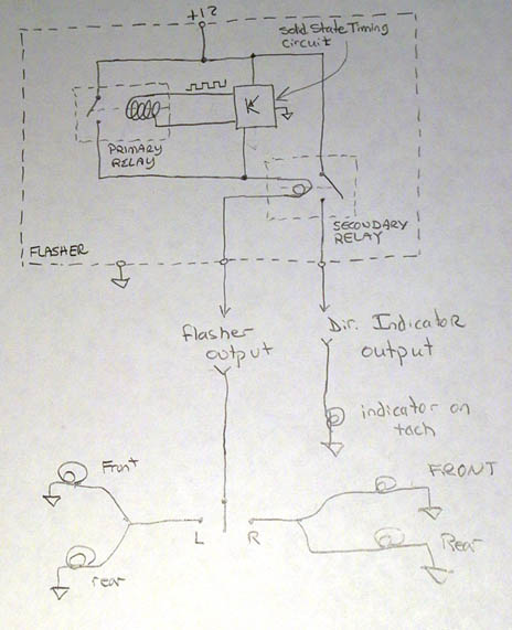 There are three parts of the flasher. The primary relay (I'll call it) switches on and off and provides an on/off voltage to ANYTHING connected to it. This is controlled by the second part, a solid state timing circuit. When a load is detected, the timing circuit starts pumping out a little square wave to the coil of the primary relay, causing it to turn on and off.... By doing it this way, the frequency of the on-and-off is independent of the load, because the load on the timing circuit (ie, the relay coil) is always the same. Now it gets interesting. Notice that the output of the primary relay actually passes in series THROUGH the coil of the secondary relay. This coil is a special kind of coil that is normally used in magnetic circuit breakers rather than relays. It is a CURRENT COIL, and the secondary relay will close only when enough CURRENT is passing through it. Relays generally have voltage coils that close when the correct minimum voltage is applied. The current coil is designed to minimize voltage drop, so it is only a few turns of relatively heavy gauge wire. After it has passed through the coil of the secondary relay, it exits the flasher to be used for anything in the car that needs to flash- directional signals, hazard warning, emergency brake light, or (at least in my car) the fasten seatbelt light. The secondary relay will create a second flashing output, but only if enough current is passing through the primary flashing relay. The threshold current that trips the secondary coil will cause a secondary flashing output when the turn signals or the hazard flashers are engaged, but not when the emergency brake light or the fasten seatbelt light is engaged. They still flash because they are attached to the primary relay, which is oblivious to load, but their load isn't enough to cause the secondary output to flash. Why bother? Well, the law required a cockpit-visible indication of a burned out direction signal bulb. So if you turn on your left signal and the front bulb, say, is burned out, the rear signal will still flash, but there will be no secondary flashing output. And, you guessed it, the secondary flashing output goes to the indicator light on the dash. You can actually hear it if you sit in your car with the engine off, but turn the ignition on. Pull up on the emergency brake and listen, and then turn on one of the direction signals. The click gets audibly louder because both relays are clicking instead of just the one. I drew the '73.5-'76 circuit first, because it's easier to figure out. This secondary flashing output goes directly to the only turn signal indicator in the tach (via the blue/white wire). The other side of that indicator is grounded..... So, the driver-visible indication of a burned out bulb is- when the turn signal indicator works fine for one direction, but remains dark when you switch to signal for the other direction.... There is a bulb burned out on the latter side. Or something else that can reduce the current flow below what is required to trip the secondary relay... Like corroded contacts, corroded socket, wrong type bulb (not bright enough), bulbs replaced with LEDs, whatever that reduced the current below the flashing threshold. 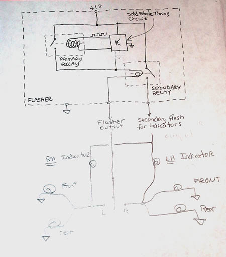 Thankfully, the flasher works the same as in the later models that only have one indicator, which was covered in my earlier post. When you look the indicators, it gets weird- The same blue/white wire goes to the tach, and it hooks to BOTH bulbs. The other lead of each bulb, instead of going to ground, actually goes to the turn signal circult that goes off to the bulbs themselves. BUT WAIT!!! The LEFT indicator is connected to the RIGHT circuit, and the RIGHT indicator is connected to the LEFT circuit. If you study what's going on, you see it. When the left turn signal is on, the flashing signal trailing out to the bulbs is +12v/0/+12v/0/+12v/0 and on and on. The same signal is coming out from the secondary relay to both indicator lights. This signal is in phase with the primary flashing signal, so the indicator that is connected to the left turn signal WILL NOT FLASH because it will see +12v on both leads at the same time, or 0 on both leads at the same time. There will never be a voltage differential that will cause it to light up. And which indicator do you NOT want to see flash when the left signal is on? That's right- the RIGHT one. So what happens with the left indicator? It flashes! Because one lead is connected to the same secondary flashing output that the other indicator is connected to, but its second lead, which is connected to the RIGHT signal circuit IS GROUNDED THROUGH THE TURN SIGNAL BULB FILAMENTS THEMSELVES! (let sink in) This grounding scheme works because the indicator bulb is much lower wattage (meaning much higher resistance) than the main signal bulbs, so it lights up and limits the current in the circuit to a level below which the main bulbs turn on. So that's pretty tricky, but it's not over yet! What happens when a bulb is out? Well, the secondary relay in the flasher stays open, as before. But what a weird-ass result that has- BOTH INDICATORS FLASH TOGETHER when the side with the missing/wrong/corroded/LED/whatever problem is turned on. If you look at the circuit, you can see what's going on- with the output from the secondary relay floating, you have both indicator bulbs, in series, completing the circuit from the side that's on (+12v or thereabouts) to the side that's off, and grounding through the filaments of the big signal bulbs again! The indicators are a bit dimmer, because they're wired in series, but they flash together. If you replaced your indicators with LEDs, this cannot happen. The back-to-back series LEDs will block current flow. In this case the indicator that a bulb is out is that the indicator LED on the side with the bad bulb will remain off when that side's turn signal is turned on. So that's about it. These two installments show the before and after circuits for incorporating early dual indicators into late tachs... Plus enough info to dispel myths that are drifting around about grounding problems, diodes in the harness, etc, etc, etc..... You can now also figure out how to diagnose problems better. For example, if the dash indicator light is on, but doesn't flash, it has to be a bad flasher. If the signals flash, but the indicator is steady, it's the secondary relay in the flasher. If both stay on, it's the primary relay in the flasher (probably) or the solid state timing circuit in the flasher (unlikely). etc, etc, etc.... |
|
|
|
| lapuwali |
Jul 19 2006, 06:17 PM
Post
#6
|
|
Not another one! Group: Benefactors Posts: 4,526 Joined: 1-March 04 From: San Mateo, CA Member No.: 1,743 |
What are relays? How do they work? What are they for?
Relays are electrically switched switches. This sounds silly at first, but they're actually very useful when you need to switch a large amount of current. Headlights are a good example. Together, the low beams use about 110W, or about 8-9A of current. This is a fairly high amount of current to run though the headlight switch, which is fairly small and actually has several smaller switches inside it. So, using a relay, a very small current (far less than 1A) can be run through the headlight switch, which switches the relay, which switches the 9A current required to run them. Relays are also useful in circuits where you need to have one electrical device control another. The fuel injection computer switching the fuel pump is a good example. When you switch on the key, the fuel pump runs for a few seconds to build pressure so you can start the car. The ECU then turns off the fuel pump until it detects you're actually starting the car. This way, the fuel pump isn't running while the engine is off, which can prevent a fuel fire. The headlight circuit also uses several relays to control the motors that raise and lower the lights. The relays used here are what I called the "5-post" type, which menas they actually have two switchable circuits inside. One is on, and the other is off. When you switch the relay, the first goes off, and the other goes on. What I call "4-post" relays only switch one circuit on or off, which is all you need for, say, the fuel pump. The round relays found in the 914 are interchangable, so if one circuit is failing and you suspect the relay, you can swap the relay with another circuit to see if that fixes the problem. The relays are also not sealed, so you can pop the cover off to clean them. Dirt on the contacts can sometimes be a problem. Note that a 4-post relay won't work in place of a 5-post relay, but a 5-post will work in place a four post. I'm not sure, but I believe all of the relays on the 914 are the 5-post type, even though very few actually need to be. |
|
|
|
| lapuwali |
Jul 19 2006, 06:39 PM
Post
#7
|
|
Not another one! Group: Benefactors Posts: 4,526 Joined: 1-March 04 From: San Mateo, CA Member No.: 1,743 |
What causes a fuse to blow?
This is an unexpectedly complicated topic. All electrical connections have a certain amount of resistance. Resistance limits the current that can flow through the wire. The wire itself will have some resistance (usually very low), and the items that do useful things, like lights, motors, and radios, will have a higher resistance. A dash bulb, for example, will be rated at 2W, so about 1/4A will flow through it (2W / 13v), which is a fairly small current. A dash bulb has a very high resistance. A headlight bulb will be rated at about 55W, so about 4A will flow though it, so it has lower resistance. A 2W dash bulb needs a much thinner wire to pass its lower current than a headlight bulb does. Current through a wire causes heat. Too much current through a wire will melt the insulation, which may catch fire. The heat given off may also set something else on fire, like seat or dash fabric, or fuel. Wires are sized by the amount of current they are normally expected to carry. Usually, the smallest wires possible are used to save bulk, weight, and cost of the wiring harness. If the resistance in a circuit becomes very low (near 0), then you get a short, and far more current than is desired will try to flow through the wire, which will get very hot, and perhaps start a fire. Simply disconnecting a power wire and touching it to a ground post will cause a short. To prevent damage to the wire, and esp. stop a fire, most of the circuits are fused. The fuse is nothing more than a strip of wire that's calibrated to burn up when a set current passes through. Most of the fuses in the 814 fusebox are 8A fuses, usually there to protect circuits made mostly of 18-20 gauge wire. The fuse will burn up long before a 20g wire will, so if a short occurs, the fuse will blow, and the temperature of the wire will never get high enough to burn. The usual causes of a fuse blowing is simply something that's disconnected and dangling. Sometimes, it's caused by a wire that's chafed from rubbing on the sharp edge of a hole. The wire touches the body, and you have a short. Now and again, a device like a switch or a motor will develop an internal short because of some mechanical fault. The usual divide-and-conquer approach mentioned in the problem solving section will work to find the short. You know which fuse is blowing, so follow all of the circuits attached to that fuse until you find the shorted connection. One problem common to 914s and many other European cars of the period is that the bullet fuses are made of materials that corrode over time, and that corrosion will insulate the fuse, making it appear as though it's blown. The contact surface of the bullet ends against the fusebox "fingers" is also very small. Rotating the fuse in the holder can often scrape off enough of the corrosion to allow the fuse to work. These fuses can also sometimes blow but still appear to be intact. If you remove the fuse from the holder, the metal part of such a fuse will usually crumble, even though it looked fine in the fusebox. |
|
|
|
|
1 User(s) are reading this topic (1 Guests and 0 Anonymous Users)
0 Members:

|
Lo-Fi Version | Time is now: 8th June 2026 - 10:32 PM |
Invision Power Board
v9.1.4 © 2026 IPS, Inc.