|
|
|
Porsche, and the Porsche crest are registered trademarks of Dr. Ing. h.c. F. Porsche AG.
This site is not affiliated with Porsche in any way. Its only purpose is to provide an online forum for car enthusiasts. All other trademarks are property of their respective owners. |
|
|

  |

| GWN7 |
 Jul 15 2006, 02:42 AM Jul 15 2006, 02:42 AM
Post
#1
|
|
King of Road Trips  Group: Members Posts: 6,280 Joined: 31-December 02 From: Winnipeg, MB, Canada Member No.: 56 Region Association: Northstar Region |
While having a tec inspection done for the local Ax I found a tie rod end was in bad shape (rubber boot torn/too much play) and decided to upgrade to the Turbo Tie rods.
You can check yours by having someone wiggle the wheel from side to side (same check for too much wheel bearing play) and watch what your tie rod does. It it moves very easy it's time to replace or have someone who knows more than you look at them. (IMG:style_emoticons/default/biggrin.gif) I ordered the replacement turbo tie rods from GPR. They were $149 at the time of writing this. You will also need two zip ties. I used black ones about 6" long. Tools needed: 17mm socket, 22mm wrench, two pair of needle nose plyers, tie rod wrench, pickle fork, channel locks or small pipe wrench, hammer. 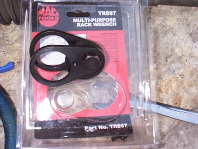 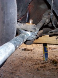 First loosen your tire bolts and then jack up the front of the car and place jackstands underneath so it is safe to crawl underneath it. Clean your work area. I did this outside and used a air blower to get rid of any junk that was laying on the ground. Nothing worse than laying or sitting on a sharp rock. Take the tires off, noting their relative possition in the wheel wells to the outside of the car. This will help in aligning the tie rods after instaling them. You can use a straight edge and measure and mark the tires edges from the fenders before you remove them to get the toe in closer. Put the straight edge (piece of wood or whatever you have) against the tire before removal and measure the distance from the edge of the fenders front and back with a ruler to the straight edge. Mark down those numbers for later. Then pull the cotter pin out of the tie rod end. Use the plyers to do this and discard the old pin. New pins are supplied with the kit. Use the 17mm socket to loosen the castelated nut on top of the tie rod. 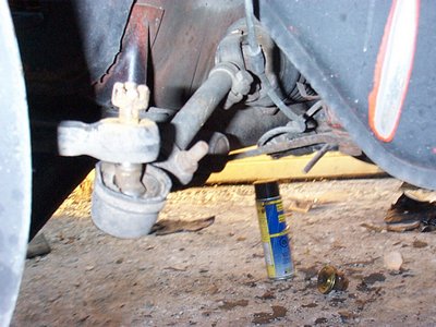 Then insert the pickle fork between the tie rod end and the steering arm which is attached to the front strut and use the hammer to loosen the two pieces. Wiggle the pickle fork between hitting it and the parts come right off. You can the swing the front brake assembley out of the way. Picture shows the bad tie rod flopped over, note the torn off rubber boot. 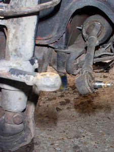 Next you have to remove the bushing and the support/steering limiter. This is shown below. It is the ball shaped yoke with the bolt thru it. You can use the channel locks or small pipe wrench to undo this part. When undone, the bellows and retaining springs will come off with some gentle pulling towards you. The bellows is the rubber part behind the bushing. 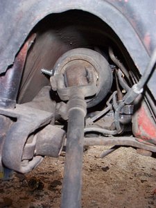 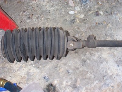 Unscrew the tie rod end off the new tie rod and set aside for now. Next screw in the new tie rod to where the old one came out of. The big flat washer that is in the kit goes on the tie rod before it gets screwed in. It acts as a steering stop on the new rod. 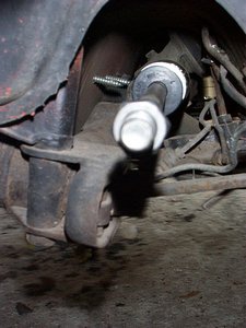 This is where you use the tie rod wrench. It slides over the rod and goes up against the flat washer and using a socket you tighten the cam on the wrench which tightens the tie rod to the car. You can buy a specialty wrench to do just these tie rods, but I opted to get one I could use on other applications. Next slide the retaining spring (off the old bellows) that fits the large end of the new bellows on to the end of the new tie rod. Then slide the new bellows that came in the kit on to the new tie rod. Big end goes on first. Next you slide under the car to where you can see the end of the steering rack where the bellows attaches to the steering rack. There is a V shaped channel at this point. 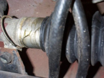 Now you should be very glad you cleaned the area of anything sharp by now or mabey the pain keeps you focused while your laying under the car. (IMG:style_emoticons/default/biggrin.gif) Now use the two pair of needle nose plyers to grab the sides of the bellows and wiggle it on to the steering rack, till the first grove goes into the V channel. Slide the retaining spring on to the first groove and that part is done. I tryed for a long time at this point to get the outside portion of the bellows on to the the new stop and then add the retaining spring and finally gave up on that idea and went and got a zip tie to attach it. Put the zip tie on till it just starts to click and push the bellows back with one hand till it's in place and then pull the zip tie tight. Trim off excess zip tie with plyers. Shown snipped off in the next picture. Next screw on new tie rod end. 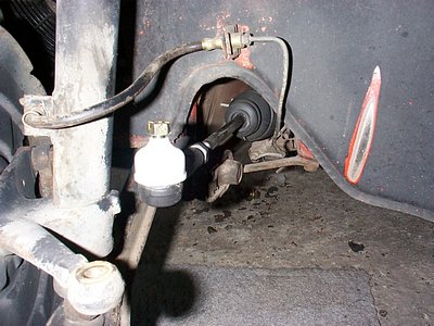 Remove the nut and protective cap. 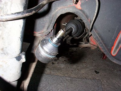 Size up the alignment. This can be done by putting the tire back on and checking the measurements you made with the straightedge and ruler when you started (now where did you put those measurements?). You adjust the tie rod length by screwing it in or out till it matches the steering arm. 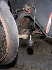 Insert the tie rod into the steering arm and install the new castel nut and the new cotter pin (supplied in the kit). 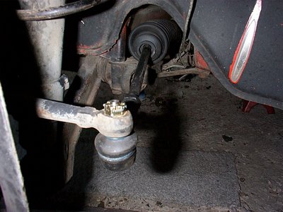 Tighten up the retaining nut on the rod with your 22mm wrench to hold the tie rod in place. 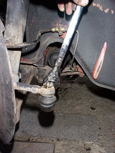 Put your tires back on and hand tighten the lug bolts. Remove jack stands and re tighten lug bolts with the tires back on the ground. Put jack & stands away, along with your tools. Wash hands and go for a drive..... |
   |

 
|
| dinomium |
Jul 15 2006, 02:54 AM
Post
#2
|
|
Git on a chair son, all the good stuff is goin over yer head! Group: Benefactors Posts: 2,777 Joined: 2-January 03 From: Bremerton, WA Member No.: 74 Region Association: Pacific Northwest |
That is how it looked when Dave and Kevin were doing mine! When I did it myself, it still looked like that!
You should get mono balls now then get a really good agressive street alighnment! Rock on! |
|
|
|
| McMark |
Jul 15 2006, 04:21 AM
Post
#3
|
|
914 Freak! Group: Retired Admin Posts: 20,179 Joined: 13-March 03 From: Grand Rapids, MI Member No.: 419 Region Association: None |
Thanks Bruce! I moved things around a bit. (IMG:style_emoticons/default/wink.gif) Hope you don't mind.
|
|
|
|
| Allan |
Jul 15 2006, 08:18 AM
Post
#4
|
|
Teenerless Weenie Group: Members Posts: 8,373 Joined: 5-July 04 From: Western Mesopotamia Member No.: 2,304 Region Association: Southern California |
My kit came with nylock nuts on the tie-rod end. (IMG:style_emoticons/default/blink.gif)
This is perfect timing. Doing this today. Hope I don't melt in the heat though... |
|
|
|
| So.Cal.914 |
Jul 15 2006, 08:34 AM
Post
#5
|
|
"...And it has a front trunk too." Group: Members Posts: 6,588 Joined: 15-February 04 From: Low Desert, CA./ Hills of N.J. Member No.: 1,658 Region Association: None |
Should have showed the pickle fork, alot of people have no idea what that is. I
mention it and people look at me like I am growing a third eye. Nicely done. |
|
|
|
| GWN7 |
Jul 15 2006, 12:57 PM
Post
#6
|
|
King of Road Trips Group: Members Posts: 6,280 Joined: 31-December 02 From: Winnipeg, MB, Canada Member No.: 56 Region Association: Northstar Region |
QUOTE(McMark @ Jul 15 2006, 03:21 AM)  Thanks Bruce! I moved things around a bit. (IMG:style_emoticons/default/wink.gif) Hope you don't mind. Np, I couldn't figure out how to do it that way, Thanks QUOTE Should have showed the pickle fork, alot of people have no idea what that is. I mention it and people look at me like I am growing a third eye. Nicely done. The Pickle fork is shown in Picture 2....it's just that it's in use. I figured someone who had never used one would like to know where it goes. You can see what a set of them looks like here: http://www2.northerntool.com/product/200311609_200311609.htm BTW I did melt in the heat while doing this....it was nice and cool under the car. (IMG:style_emoticons/default/biggrin.gif) |
|
|
|
| Kalva |
Sep 20 2010, 04:14 PM
Post
#7
|
|
Newbie Group: Members Posts: 38 Joined: 25-June 10 From: Long Island NY Member No.: 11,882 Region Association: North East States |
Very Helpful I just finnished.... (IMG:style_emoticons/default/driving.gif) (IMG:style_emoticons/default/driving.gif)
|
|
|
|
|
1 User(s) are reading this topic (1 Guests and 0 Anonymous Users)
0 Members:

|
Lo-Fi Version | Time is now: 20th April 2024 - 05:59 AM |
Invision Power Board
v9.1.4 © 2024 IPS, Inc.