|
|
|
Porsche, and the Porsche crest are registered trademarks of Dr. Ing. h.c. F. Porsche AG.
This site is not affiliated with Porsche in any way. Its only purpose is to provide an online forum for car enthusiasts. All other trademarks are property of their respective owners. |
|
|

  |

| vesnyder |
 Jul 25 2006, 08:49 AM Jul 25 2006, 08:49 AM
Post
#1
|
|
Senior Member  Group: Members Posts: 680 Joined: 14-April 05 From: Cleveland, OH Member No.: 3,933 |
Anybody have a legible/usable vacuum schematic for a D-jet 1.7? My hose set is not complete and need to replace and it is not clear all the hoses are connected properly.
BTW - my car is idling at ~3k+ RPM so I have some serious issues! |
   |

 
|
| Cap'n Krusty |
Jul 25 2006, 08:58 AM
Post
#2
|
|
Cap'n Krusty Group: Members Posts: 10,794 Joined: 24-June 04 From: Santa Maria, CA Member No.: 2,246 Region Association: Central California |
Good vacuum diagrams over at the Pelican site. The Cap'n
|
|
|
|
| Dr Evil |
Jul 25 2006, 09:02 AM
Post
#3
|
|
Send me your transmission! Group: Members Posts: 22,995 Joined: 21-November 03 From: Loveland, OH 45140 Member No.: 1,372 Region Association: MidAtlantic Region |
Here ya go, Vance.
http://www.pelicanparts.com/914/technical_...el_diagrams.htm |
|
|
|
| r_towle |
Jul 25 2006, 09:15 AM
Post
#4
|
|
Custom Member Group: Members Posts: 24,574 Joined: 9-January 03 From: Taxachusetts Member No.: 124 Region Association: North East States |
hi,
I have no diagram, I think that there are some pictures on PP web site, and possibly in the classics section on this site. If not, I have a 1.7...I can talk you though it... Rich |
|
|
|
| vesnyder |
Jul 25 2006, 11:09 AM
Post
#5
|
|
Senior Member Group: Members Posts: 680 Joined: 14-April 05 From: Cleveland, OH Member No.: 3,933 |
Thanks guys! Diagram looks pretty detailed, but I will ping you Rich if there is something that does not make sense,
|
|
|
|
| Bleyseng |
Jul 25 2006, 11:19 AM
Post
#6
|
|
Aircooled Baby! Group: Members Posts: 13,034 Joined: 27-December 02 From: Seattle, Washington (for now) Member No.: 24 Region Association: Pacific Northwest |
pic of a 1.7L
Attached image(s) 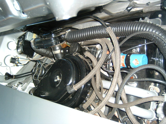
|
|
|
|
| vesnyder |
Jul 25 2006, 12:36 PM
Post
#7
|
|
Senior Member Group: Members Posts: 680 Joined: 14-April 05 From: Cleveland, OH Member No.: 3,933 |
I've included the schematic and hopefully you guys can provide some clarification. Most of mine is accurate, but I have other other vacuum connectors/locations. On mine, adjacent to the fan shroud and oil filler I have three connectors - one pointing up and two horizontal - one facing back and the other facing the passengers side. I also have another connection hold very close to the MPS connector on the manifold (?). The car revs close to 4000 until I close this one off, then the car just about dies? The breather lines that come out of the valve train area - where do they connect to? Question - does the MPS have 4 wires connected to it? What is the round thing adjacent to the Air Filter, that has the two lines - one going to the manifold and another going to the intake boot? More questions than I thought?
Lastly, when testing it just now, the car revved wildly - past redline - and I had to shut it off. Last time it did that I changed the throttle cable thinking it was sticking, but now I think it is the vacuum system making it rev - WTH could be casuing this? Attached image(s) 
|
|
|
|
| tdgray |
Jul 25 2006, 01:30 PM
Post
#8
|
|
Thank God Nemo is not here to see this Group: Members Posts: 9,705 Joined: 5-August 03 From: Akron, OH Member No.: 984 Region Association: None |
Slooooow down Vance. One thing at a time. This is somewhat complicated until you figure it out.
The first thing you describe I think was refered to me as a flashback valve. You should have two hoses coming from the heads on either side. IIRC the other short hose (off the top) goes to the air cleaner. The round thing is the AAR... very important to make the D-jet run to have this plugged in correctly. You should have a connection with a short hose from the plenum (not manifold) to the AAR. This should be a short plastic / rubber Y fitting. The small connection is a thin hose that connects to the advance on your distributor. The exit connection from the AAR should go back to the intake boot. Not really sure about your other connection you say is near the MPS. Do you have your decel valve hooked up correctly? You can run without it but it helps if you know where all the hoses go. Take some time and study both the 1.7 and 2.0 vacuum diagrams. That is how I figured it out. You'll get it. |
|
|
|
| vesnyder |
Jul 25 2006, 02:07 PM
Post
#9
|
|
Senior Member Group: Members Posts: 680 Joined: 14-April 05 From: Cleveland, OH Member No.: 3,933 |
Looking at the 2 liter diagram, it appears to be much closer to what I have. Stay tuned ...
|
|
|
|
| Air_Cooled_Nut |
Jul 25 2006, 02:24 PM
Post
#10
|
|
914 Ronin - 914 owner who lost his 914club.com Group: Members Posts: 1,748 Joined: 19-April 03 From: Beaverton, Oregon Member No.: 584 Region Association: None |
QUOTE ...On mine, adjacent to the fan shroud and oil filler I have three connectors - one pointing up and two horizontal - one facing back and the other facing the passengers side. This is part of the emissions system. The upward facing port goes to the air cleaner (top of it). The two horizontal ports connect to the top of the heads where the lifters (valve train) are, one hose per side. QUOTE I also have another connection hold very close to the MPS connector on the manifold (?). The car revs close to 4000 until I close this one off, then the car just about dies? Hard to say. Possibly the AAR (Aux. Air Regulator) which is only used when the engine is cold. Look for an object that has only two hoses going to it and the object has a wire coming out from the bottom of it. That's the AAR. Once it (and thus the engine) are warmed up, the rotating valve inside will cut off the air supply and removing the hose (from the top of the air cleaner side) won't have an effect and there will be no vacuum present from the hose. QUOTE The breather lines that come out of the valve train area - where do they connect to? See first comment above. QUOTE ...What is the round thing adjacent to the Air Filter, that has the two lines - one going to the manifold and another going to the intake boot? More questions than I thought? that would be the AAR as mentioned above. QUOTE Lastly, when testing it just now, the car revved wildly - past redline - and I had to shut it off. Last time it did that I changed the throttle cable thinking it was sticking, but now I think it is the vacuum system making it rev - WTH could be casuing this? A disconnected vacuum line or your idle adjustment is waaaay off. |
|
|
|
| tdgray |
Jul 25 2006, 02:51 PM
Post
#11
|
|
Thank God Nemo is not here to see this Group: Members Posts: 9,705 Joined: 5-August 03 From: Akron, OH Member No.: 984 Region Association: None |
In light of Toby's last comment (no offense Toby).
I just went thorugh this whole ordeal. Listen to me carefully. THE D-JET WILL NOT IDLE PROPERLY WITHOUT THE VACUUM HOSES HOOKED UP CORRECTLY. I had the same problem. Idled at 5K. Hooked all the vac hoses up.. no problem |
|
|
|
| Bleyseng |
Jul 25 2006, 02:54 PM
Post
#12
|
|
Aircooled Baby! Group: Members Posts: 13,034 Joined: 27-December 02 From: Seattle, Washington (for now) Member No.: 24 Region Association: Pacific Northwest |
look at this pic of the 1.7L hoses
Attached image(s) 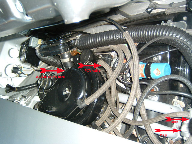
|
|
|
|
| Bleyseng |
Jul 25 2006, 02:58 PM
Post
#13
|
|
Aircooled Baby! Group: Members Posts: 13,034 Joined: 27-December 02 From: Seattle, Washington (for now) Member No.: 24 Region Association: Pacific Northwest |
73 2.0L hoses
Attached image(s) 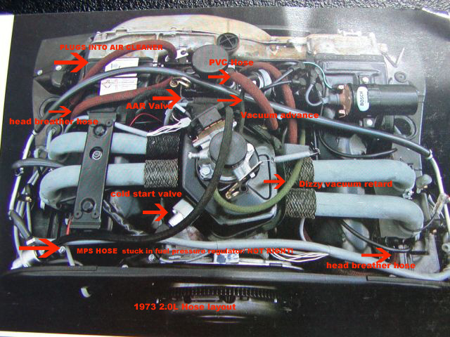
|
|
|
|
| Air_Cooled_Nut |
Jul 25 2006, 03:40 PM
Post
#14
|
|
914 Ronin - 914 owner who lost his 914club.com Group: Members Posts: 1,748 Joined: 19-April 03 From: Beaverton, Oregon Member No.: 584 Region Association: None |
QUOTE(tdgray @ Jul 25 2006, 01:51 PM)  In light of Toby's last comment (no offense Toby)... None taken...you're correct! The fuel injection systems are sensitive to vacuum leaks, great and small (IMG:style_emoticons/default/smile.gif) A disconnected hose from the AAR would do this as it bypasses the idle. The hose collars that connect the intake runners to the plenum should be tight as well as they can be a source of intake leaks. |
|
|
|
| Dave_Darling |
Jul 25 2006, 04:46 PM
Post
#15
|
|
914 Idiot Group: Members Posts: 14,982 Joined: 9-January 03 From: Silicon Valley / Kailua-Kona Member No.: 121 Region Association: Northern California |
M-A's 1.7 diagram is for a very early 1.7, which doesn't have as many things hooked up to it as the later ones. If someone else would like to do a 72 or 73 1.7 diagram, Pelican would be more than happy to host it!!
--DD |
|
|
|
| vesnyder |
Jul 25 2006, 07:42 PM
Post
#16
|
|
Senior Member Group: Members Posts: 680 Joined: 14-April 05 From: Cleveland, OH Member No.: 3,933 |
I've included a pic of the plenum rear passengers side. There are three outlets. The one with the arrow is the one I am confused about? This port draws a vacuum and when closed idles normally, when opened the car idles at 3,500+ RPM. What does this hose connect to? I've attached another version of the vacuum schematic.
Attached image(s) 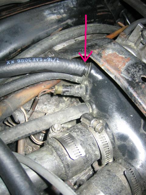 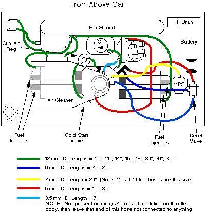
|
|
|
|
| Bleyseng |
Jul 25 2006, 08:17 PM
Post
#17
|
|
Aircooled Baby! Group: Members Posts: 13,034 Joined: 27-December 02 From: Seattle, Washington (for now) Member No.: 24 Region Association: Pacific Northwest |
its a 1.7l and that hose connects to the charcoal canister return line hose. Plug it for now at the plenum to simplify your vacuum leaks issues. (IMG:style_emoticons/default/mueba.gif)
|
|
|
|
| vesnyder |
Jul 25 2006, 08:51 PM
Post
#18
|
|
Senior Member Group: Members Posts: 680 Joined: 14-April 05 From: Cleveland, OH Member No.: 3,933 |
I plug it the car stalls, and if I leave it wide open the car idles at 3k+? I currently do not have the charcoal cannister. The car continues to rev regardless of what vacuum lines I have connected - I am getting concerned I am going to damage th e motor?If
|
|
|
|
| Dave_Darling |
Jul 25 2006, 09:47 PM
Post
#19
|
|
914 Idiot Group: Members Posts: 14,982 Joined: 9-January 03 From: Silicon Valley / Kailua-Kona Member No.: 121 Region Association: Northern California |
I don't think the charcoal cannister system should be hooked directly up to the intake manifold ("plenum") in any event.
A large vacuum leak will cause a 3000+ RPM idle on a D-jetronic motor. Plug that fitting, and open up the idle bypass screw on the throttle body until it idles. There are three "flavors" of vacuum. The first is ambient-pressure air, which comes from "upstream" of the throttle body. The second is manifold vacuum, which comes from "downstream" of the throttle body. The third is "ported vacuum", which comes from a specific location on the throttle body itself. There are several components that hook into the vacuum system and "do stuff". Some of these are not present on early cars. The first is the MPS, the silver hand-grenade looking thing that has one vacuum hose and one four-wire bundle plugged into it. It should get plugged into manifold vacuum. The next component is the Auxiliary Air Regulator. It lets air go from "upstream" of the throttle to "downstream" when the engine is cold. It has one hose that hooks to ambient air, and one to manifold vacuum. The third component is the Decel Valve. It bleeds air from "upstream" to "downstream" when the manifold vacuum is high enough. It has one large line plugged into ambient air, and one to manifold vacuum. It also has a smaller "control" line going to manifold vacuum. The final lines would go from the throttle body to the distributor dashpot (the vacuum thingy on the distributor). The one that is there in all 914s actually carries manifold vacuum, and it works the vacuum retard system. It hooks to the retard fitting on the dashpot, which is the fitting that points back toward the distributor body. (The vacuum signal may be slightly different than "regular" manifold vacuum due to porting/venturi effects, but it should be reasonably close much of the time.) The other one is not there on many 74+ 914s, and that carries ported vacuum to the advance fitting on the distributor--the one that points away from the distributor body. There are two more systems that use hoses to move air around in the engine bay. The Positive Crankcase Ventilation (PCV) system helps deal with air pressure inside the crankcase and with oil vapors in there as well. Some 914s have hoses from the cylinder heads (the parts where the rocker arms live) that connect to a funny T fitting, and then get plumbed into ambient air. These cars also have a line from the oil filler to manifold vacuum, though there is a PCV valve in the filler. The rest of the 914s have the line from the oil filler going to ambient air. The other air-line system is the charcoal cannister system. A fitting on the fan shroud or engine tin takes pressurized air and pushes it into the charcoal cannister, where it picks up fuel vapors. Another line brings these into the air cleaner where they are sucked in and burned rather than causing pollution. There are also one or two hoses from the cannister to the "expansion tank" that sits on top of the fuel tank. Then you have the fuel hoses, of course.... Anyway, I hope this helps. You should be able to use the general principles above to sort out the vacuum hose connections. --DD |
|
|
|
| Air_Cooled_Nut |
Jul 25 2006, 09:58 PM
Post
#20
|
|
914 Ronin - 914 owner who lost his 914club.com Group: Members Posts: 1,748 Joined: 19-April 03 From: Beaverton, Oregon Member No.: 584 Region Association: None |
Damn Dave, nice explaination! Very well thought out and presented. I understand FI but you made it even simpler (IMG:style_emoticons/default/smile.gif)
|
|
|
|
|
1 User(s) are reading this topic (1 Guests and 0 Anonymous Users)
0 Members:

|
Lo-Fi Version | Time is now: 8th May 2024 - 10:32 PM |
Invision Power Board
v9.1.4 © 2024 IPS, Inc.