|
|
|
Porsche, and the Porsche crest are registered trademarks of Dr. Ing. h.c. F. Porsche AG.
This site is not affiliated with Porsche in any way. Its only purpose is to provide an online forum for car enthusiasts. All other trademarks are property of their respective owners. |
|
|

  |

| GS Guy |
 Feb 24 2010, 07:39 PM Feb 24 2010, 07:39 PM
Post
#281
|
|
Member  Group: Members Posts: 243 Joined: 8-July 04 From: Columbia, MD Member No.: 2,325 Region Association: North East States |
That's a pretty trick modification to the electronic speedo adapter Scott! I'm going to have to look into doing that to mine. The angle drive serves no real purpose with the electronic sensor, except to adapt it to the trans!
It looks like you cannibalized some parts from the angle drive - obviously the nut, but what else? Sounds like some internal portion that presses into your custom bushing? Material of the new bushing? What kind of press fits did you use - couple of thousandths? Is the end product just the 3 new parts added to the sensor housing - the new bushing, piece pressed into the inside and nut on the outside - all this simply pressed into the sensor housing? I like it! Jeff |
   |

 
|
| Amenson |
Feb 24 2010, 09:09 PM
Post
#282
|
|
That's opposite lock!! Group: Members Posts: 645 Joined: 27-May 05 From: Dublin, OH Member No.: 4,154 Region Association: None |
QUOTE(GS Guy @ Feb 24 2010, 05:39 PM)  That's a pretty trick modification to the electronic speedo adapter Scott! I'm going to have to look into doing that to mine. The angle drive serves no real purpose with the electronic sensor, except to adapt it to the trans! It looks like you cannibalized some parts from the angle drive - obviously the nut, but what else? Sounds like some internal portion that presses into your custom bushing? Material of the new bushing? What kind of press fits did you use - couple of thousandths? Is the end product just the 3 new parts added to the sensor housing - the new bushing, piece pressed into the inside and nut on the outside - all this simply pressed into the sensor housing? I like it! Jeff I only used the nut from the angle drive. The piece in the drawing is the only part that I made. The original was brass but I did not have any in the shop at work so I used aluminum. I reused the pressed in brass bushing from the original speedo piece. The press fits were ~3-4 thou...a bit tight but matched the original parts. The brass bushing presses into the aluminum piece that I made and that presses into the speedo housing. If you want the Sketchup, file let me know and I can email it to you. Oh, I had to drill out the rivets that hold it together. I replaced them with 3x20 mm hardware. Scott |
|
|
|
| Amenson |
Mar 13 2010, 09:07 PM
Post
#283
|
|
That's opposite lock!! Group: Members Posts: 645 Joined: 27-May 05 From: Dublin, OH Member No.: 4,154 Region Association: None |
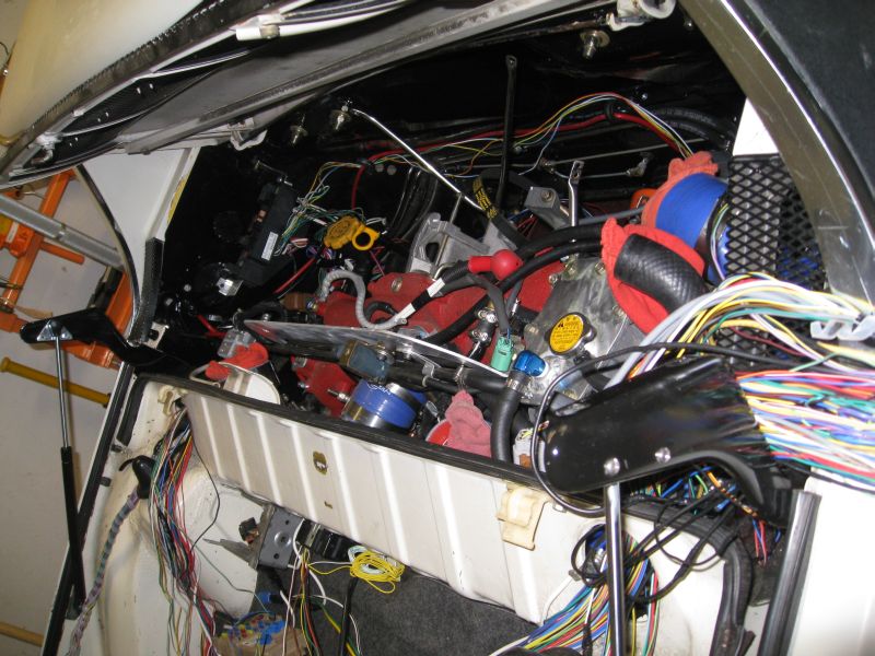
Well, it is time to dig back into the wiring harness. I started by troubleshooting the only non-functioning part of the electrical system...the alternator. Of course I assumed that I messed up something in the initial harness modification so I spent much longer than normal coming to accept the reality that the alternator is dead. In order to pull the alternator the intercooler had to come out and in order to remove the intercooler the rear trunk had to come off.
 With that resolved I started in on the wiring. The task is to separate the stuff that needs to be in the dashboard area and the stuff that does not. When I first started back on the wiring I had the distinct feeling of being overwhelmed again. After an hour or so I regained my familiarity with the schematic and it was full steam ahead. 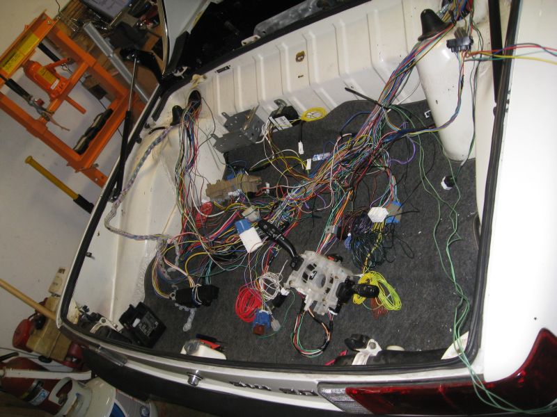 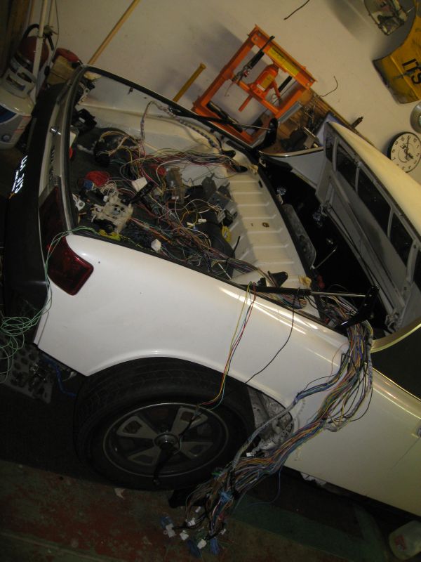 A few more long days like this and I may be able to start it from the driver's seat finally! Scott |
|
|
|
| GS Guy |
Mar 14 2010, 09:19 AM
Post
#284
|
|
Member Group: Members Posts: 243 Joined: 8-July 04 From: Columbia, MD Member No.: 2,325 Region Association: North East States |
QUOTE(Amenson @ Feb 24 2010, 10:09 PM) I only used the nut from the angle drive. The piece in the drawing is the only part that I made. The original was brass but I did not have any in the shop at work so I used aluminum. I reused the pressed in brass bushing from the original speedo piece. The press fits were ~3-4 thou...a bit tight but matched the original parts. The brass bushing presses into the aluminum piece that I made and that presses into the speedo housing. If you want the Sketchup, file let me know and I can email it to you. Oh, I had to drill out the rivets that hold it together. I replaced them with 3x20 mm hardware. Scott Hey Scott - I completed the same modification to my speedo sensor yesterday and it seems to work perfectly for mechanical fit. The only thing I found I needed beyond your description was running a 1/4" reamer through both rotor bushings while the unit was assembled (without the rotor installed) to correct a very slight mis-alignment between top and bottom bushings. I was getting some stiffness in turning the rotor after assembly, kissing it with the reamer cleaned it up perfectly. Now about that spaghetti... sure that engine doesn't have some Italian blood? (IMG:style_emoticons/default/biggrin.gif) Jeff |
|
|
|
| ruby914 |
Aug 3 2010, 09:55 AM
Post
#285
|
|
Senior Member Group: Members Posts: 720 Joined: 26-April 09 From: Hawthorne, Ca Member No.: 10,305 Region Association: None |
Scott,
Nice work. Seems you are taking a break from all the wires. I know the feeling. I saw what you were doing with your steering column and was inspired to follow. I will try to incorporate the instrument cluster and fabricate a new dash around it also. I have all I need but the WRX steering wheel. I already started cutting but I am thinking it is still too long? I see you cut it down "two more inches" so I know you have been there. I don't have the Subaru wheel yet so I wonder if the depth between the grip and shaft is shorter on the Subaru wheel? I measure about 7.5" outboard and 8.5" inboard from the stock 914 wheel to flat dash face. What did you finally come up with, from the dash, with the Subaru wheel? |
|
|
|
| Amenson |
Aug 4 2010, 10:50 AM
Post
#286
|
|
That's opposite lock!! Group: Members Posts: 645 Joined: 27-May 05 From: Dublin, OH Member No.: 4,154 Region Association: None |
QUOTE(ruby914 @ Aug 3 2010, 07:55 AM) Scott, Nice work. Seems you are taking a break from all the wires. I know the feeling. I saw what you were doing with your steering column and was inspired to follow. I will try to incorporate the instrument cluster and fabricate a new dash around it also. I have all I need but the WRX steering wheel. I already started cutting but I am thinking it is still too long? I see you cut it down "two more inches" so I know you have been there. I don't have the Subaru wheel yet so I wonder if the depth between the grip and shaft is shorter on the Subaru wheel? I measure about 7.5" outboard and 8.5" inboard from the stock 914 wheel to flat dash face. What did you finally come up with, from the dash, with the Subaru wheel? Ruby914, Thanks for the feedback. Glad you could find some of my experiences useful (IMG:style_emoticons/default/headbang.gif). Although, the steering wheel adaptation is one area where my current implementation can be improved. Currently the steering wheel sticks too far away from the dash. I do not have the stock IC installed so I measured from the back of the steering wheel to the vertical face of the dash along the steering column and the wheel is 10" away. This will be difficult to change and there is not so much room if you intend to use the Subaru plastic column cover. For me it is not much of a problem because I am short and made my pedal box position adjustable. I will have to recline my seat yet to get the perfect seating position. There is also a problem on the back side. The shaft sticks out a bit too far and it required that I shorten parts of the intermediate shaft so that I could slide the knuckles as far over the splines as possible to avoid exceeding the max working angle of the knuckles. Before I did this I had a bit of binding. I would recommend shortening the back side even more than I did so that the shaft ends up in the same place as stock. This will require a modified/different mounting method. Eventually I will do it again, maybe this winter. Hopefully you can refine the design so that I can copy you! As for the wires...I have actually started to revisit them again the past couple of weeks. I have not posted any pictures because a bundle of wires looks like a bundle of wires no matter how much time I put into them. I did have a bit of a breakthrough...maybe more accurately, a reason to redo a whold bunch of work. After much measuring and many mental iterations of wire routing, I think that I have figured out a very clean way to run the wires with a minimal amount of harness stretching. In some areas I may eventually get to shorten a few sections. If I move the main fuse box to the front where the old master cylinder reservoir was located and move the ECU to the center tunnel just in front of the rear access panel, I should be able to mount the secondary fuse box and relays under the dash or mabye under the front hood someplace. This will put all of the connectors for the Instrument cluster, switches, IG, ...etc in the proper place. In order to do this though, it required pulling the pins for most of the wires so that I can separate the right and left engine bundles from each other and from the wires that go to the dash area. This is a very tedious process of getting the pins out of the connectors, fishing the wires out of the bundle running it back with the other wires for the same location and then getting the pin back in the correct place in the original connector. So far there have been ~10 wires that take short cuts that I have had to mark, cut and eventually extend. I have a few more hours of reorganizing before I can lay the harness in the car to confirm if my plan will work. Stay tuned. Cheers, Scott |
|
|
|
| ruby914 |
Aug 12 2010, 10:29 AM
Post
#287
|
|
Senior Member Group: Members Posts: 720 Joined: 26-April 09 From: Hawthorne, Ca Member No.: 10,305 Region Association: None |
Scott, I did some more cutting as seen in this photo and cut 1/4" off of each end of the intermediate shaft. I drilled a new hole about 7/8' AFT of the original mount hole so all this gained me an extra 7/8", if I don't get a bind. I also trimmed the cover until I got to where the back cover snaps together. This just fit but it may be better to trim the dash so the cover fits inside. I may still need to do that. Were you trying to keep the tilt feature? I really want to keep that but I think I will have to weld on a bar to mock a longer steering column and have that pivot around the first U-joints. That will be a hard fit but other wise it seems to rotate too easy when locked and I think it will bind at any other pivot location. I put my ECU behind the passenger seat you can see how that fit here http://z8.invisionfree.com/ClubNARP/index.php?showtopic=5431 Attached image(s) 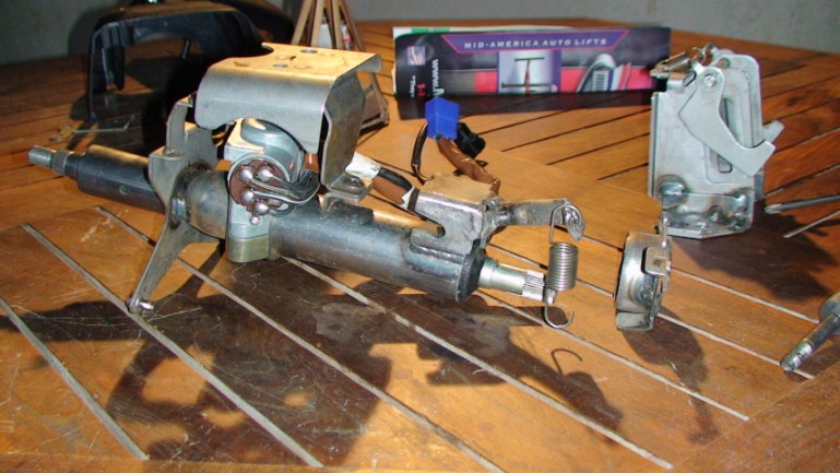
|
|
|
|
| Amenson |
Aug 15 2010, 07:52 AM
Post
#288
|
|
That's opposite lock!! Group: Members Posts: 645 Joined: 27-May 05 From: Dublin, OH Member No.: 4,154 Region Association: None |
QUOTE(ruby914 @ Aug 12 2010, 08:29 AM) Scott, I did some more cutting as seen in this photo and cut 1/4" off of each end of the intermediate shaft. I drilled a new hole about 7/8' AFT of the original mount hole so all this gained me an extra 7/8", if I don't get a bind. I also trimmed the cover until I got to where the back cover snaps together. This just fit but it may be better to trim the dash so the cover fits inside. I may still need to do that. Were you trying to keep the tilt feature? I really want to keep that but I think I will have to weld on a bar to mock a longer steering column and have that pivot around the first U-joints. That will be a hard fit but other wise it seems to rotate too easy when locked and I think it will bind at any other pivot location. I put my ECU behind the passenger seat you can see how that fit here http://z8.invisionfree.com/ClubNARP/index.php?showtopic=5431 Ruby914, I checked out your thread on ClubNARP, amazing composite work. If you work out a new dash that fits the Suby cluster I would likely be interested in a copy. I did keep my steering column adjustable, if for no other reason that I could not decide where to put it permanently. There is a picture of my mount back a few pages. I moved the harness back into the car to see how everything fits. Pretty much the only place where I can get the passenger side of the engine connected at the same time as the dash stuff is with the ECU on the center tunnel. I should be able to modify the stock between the seat storage box to hide it and still have some storage. 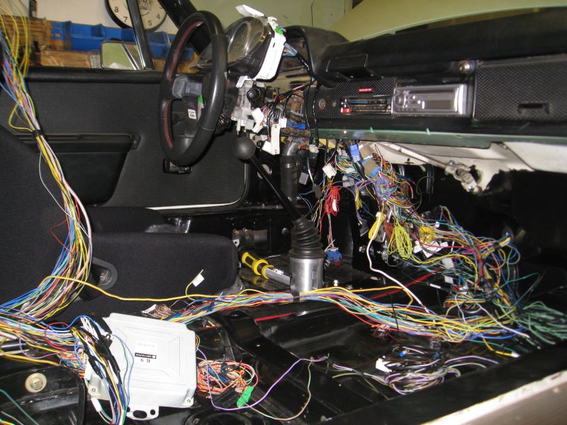 I mounted the main fuse box down where I have the battery. 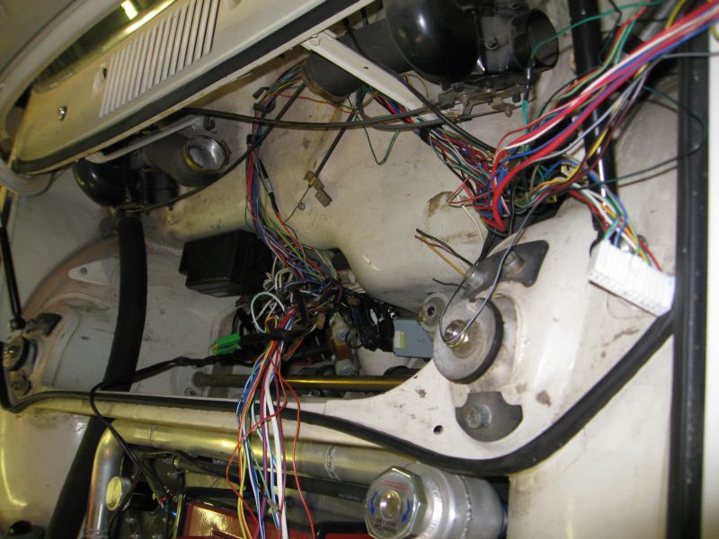 The secondary fuse box and relays seems to fit where the stock fuse box was. Although I have not figured out how to mount it. Maybe I can get that done yet this morning. Cheers, Scott |
|
|
|
| ruby914 |
Aug 20 2010, 09:45 AM
Post
#289
|
|
Senior Member Group: Members Posts: 720 Joined: 26-April 09 From: Hawthorne, Ca Member No.: 10,305 Region Association: None |
Scott,
Thanks for the compliments on the dash. Actually, you were one of the first I thought would possibly need the dash. But when I saw you were working on a custom, printed circuit board, LED instrument panel, I figured you would not need it. I don't think I would be going this direction if I had not read your thread and I would be happy to help your project come together. With your interest, I have swayed back to a more robust mold and will see what I can do to accommodate you. I will get an e-mail back to you shortly. |
|
|
|
| ruby914 |
Sep 23 2010, 10:06 AM
Post
#290
|
|
Senior Member Group: Members Posts: 720 Joined: 26-April 09 From: Hawthorne, Ca Member No.: 10,305 Region Association: None |
Scott,
I checked the resistance between the WRX and 914 fuel sending units and added a 250 ohm resister in parallel from the green to brown 914 wires. The resisters were from radio shack and only 1/2 W so I don't know what it should be or if that will last. This seems to work using the 914 sender unit for now. You are a lot more knowledgeable than i with electronics, if you see any problem let me know. I got my blinkers, and high beam lights working off the Suby column switch also but I have no 2002 Daytime running lights resister. So I still have no low beams. PN. 84057FE010 $69 - $45 is the cheapest I have found. I have been hunting around for the ohms and wattage of this part if you have an 02 maybe you could check yours for me? I also tend to wonder if the 914 lights would need a different ohms value? Edit: I got high and low working. I still don't understand the DRLs 100% but it is looking like I don't need the resister or any part of this circut. |
|
|
|
| Root_Werks |
Sep 23 2010, 10:09 AM
Post
#291
|
|
Village Idiot Group: Members Posts: 8,312 Joined: 25-May 04 From: About 5NM from Canada Member No.: 2,105 Region Association: Pacific Northwest |
(IMG:style_emoticons/default/icon8.gif)
Oh man, I stared too long at all those wires. (IMG:style_emoticons/default/lol-2.gif) Seriously, amazing work! I couldn't even begin to think I could keep track of all that. What a cool project! (IMG:style_emoticons/default/smilie_pokal.gif) |
|
|
|
| Amenson |
Sep 29 2010, 06:26 PM
Post
#292
|
|
That's opposite lock!! Group: Members Posts: 645 Joined: 27-May 05 From: Dublin, OH Member No.: 4,154 Region Association: None |
QUOTE(ruby914 @ Sep 23 2010, 08:06 AM) Scott, I checked the resistance between the WRX and 914 fuel sending units and added a 250 ohm resister in parallel from the green to brown 914 wires. The resisters were from radio shack and only 1/2 W so I don't know what it should be or if that will last. This seems to work using the 914 sender unit for now. You are a lot more knowledgeable than i with electronics, if you see any problem let me know. I got my blinkers, and high beam lights working off the Suby column switch also but I have no 2002 Daytime running lights resister. So I still have no low beams. PN. 84057FE010 $69 - $45 is the cheapest I have found. I have been hunting around for the ohms and wattage of this part if you have an 02 maybe you could check yours for me? I also tend to wonder if the 914 lights would need a different ohms value? Edit: I got high and low working. I still don't understand the DRLs 100% but it is looking like I don't need the resister or any part of this circut. Mike, Good to hear that you found a solution for the fuel sending unit. The sender in my tank has the opposite resistance to the suby unit. Not sure what to do with that yet. (IMG:style_emoticons/default/confused24.gif) My harness is out of an 05, I do not have running lights. Can't help with your issue but resistors are pretty cheap if you order one from someplace like Digikey. One thing that I have been thinking about is how to get the headlights to flip up from the Suby column. The 914 switch has a few extra contacts to work with the headlight motor. I am pretty sure that I can work it out with a relay, maybe two, but have not drawn the circuit yet. What did you come up with? Cheers, Scott |
|
|
|
| Amenson |
Sep 29 2010, 06:31 PM
Post
#293
|
|
That's opposite lock!! Group: Members Posts: 645 Joined: 27-May 05 From: Dublin, OH Member No.: 4,154 Region Association: None |
QUOTE(Root_Werks @ Sep 23 2010, 08:09 AM) (IMG:style_emoticons/default/icon8.gif) Oh man, I stared too long at all those wires. (IMG:style_emoticons/default/lol-2.gif) Seriously, amazing work! I couldn't even begin to think I could keep track of all that. What a cool project! (IMG:style_emoticons/default/smilie_pokal.gif) They are all color coded (IMG:style_emoticons/default/pinch.gif) |
|
|
|
| Amenson |
Sep 29 2010, 08:05 PM
Post
#294
|
|
That's opposite lock!! Group: Members Posts: 645 Joined: 27-May 05 From: Dublin, OH Member No.: 4,154 Region Association: None |
I thought a little bit more about the daytime running lights. Is there a relay or set of contacts that switches the resistor into the headlight circuit for DLR's?
In the end I don't think that it makes much sense having daytime running lights with flip up headlights. Unless you wanted to run your fog lights as DLR's (IMG:style_emoticons/default/idea.gif) Scott |
|
|
|
| AZ914 |
Sep 30 2010, 11:27 AM
Post
#295
|
|
914 Dumbass Group: Members Posts: 1,459 Joined: 6-January 03 From: Sunny Tucson Member No.: 98 Region Association: Southwest Region |
QUOTE(Amenson @ Sep 29 2010, 07:05 PM) I know a few guys that have their FOGS wired to be hot on ignition (switched on) instead of with the parking lights. They use them for DRLs but you can always turn them off. Works great. |
|
|
|
| ruby914 |
Oct 1 2010, 12:38 AM
Post
#296
|
|
Senior Member Group: Members Posts: 720 Joined: 26-April 09 From: Hawthorne, Ca Member No.: 10,305 Region Association: None |
I spent all this time and effort to get my low beams working thinking it was the ground that I didn't have the resister for.
I just wanted low beams, didn't even know what DRL's were for. I didn't have the DRL module and found people were taking them out of there cars, so I didn't need one. Someone told me the resister was to lower the intensity of the lights, I didn't see a need for that. I connected the DRL solenoid to ground with no resister. lights still didn't work. I was rotating the switch thinking first click was low, 2nd was high. Finally found that the high beam is push forward and pull. But at this point the ground was not connected? I looked at the circuit again. Seems I don't need the DRL module, diode and if I remove the DRL solenoid and connect the YG and YR wires that is all that is needed? I am still not sure what the first rotation of the light switch should do? I am thinking it will operate the headlight motors through the unused DRL solenoid? Again Scott, your far better with the electronics than I. Am I missing anything? Quick update: I now have all the outer lights working, the tail / running lights were last. I put a diagram on my build thread at NARP. |
|
|
|
| Britain Smith |
Nov 4 2010, 12:23 AM
Post
#297
|
|
Nano Member Group: Members Posts: 2,354 Joined: 27-February 03 From: Hillsboro, OR Member No.: 364 |
Which remote oil filter kit is this?
(IMG:http://www.914world.com/bbs2/uploads/post-4154-1251603834.jpg) -Britain |
|
|
|
| GS Guy |
Nov 4 2010, 03:35 PM
Post
#298
|
|
Member Group: Members Posts: 243 Joined: 8-July 04 From: Columbia, MD Member No.: 2,325 Region Association: North East States |
Looks like Scott's running Canton hardware for the oil system? They make some nice stuff!
|
|
|
|
| Amenson |
Nov 6 2010, 12:49 PM
Post
#299
|
|
That's opposite lock!! Group: Members Posts: 645 Joined: 27-May 05 From: Dublin, OH Member No.: 4,154 Region Association: None |
QUOTE(GS Guy @ Nov 4 2010, 01:35 PM) Looks like Scott's running Canton hardware for the oil system? They make some nice stuff! Yup, they are Canton parts. I think that I ordered them directly from Canton. Cheers Scott |
|
|
|
| Amenson |
Jan 16 2011, 06:43 PM
Post
#300
|
|
That's opposite lock!! Group: Members Posts: 645 Joined: 27-May 05 From: Dublin, OH Member No.: 4,154 Region Association: None |
OK, so I made some decent progress recently, mostly thanks to ruby914. He made me a copy of his Subaru instrument cluster adapted dash. There is a link to his build thread a few posts back and if you have not already visited it, please do. He has made some really nice parts for his car.
So back to the dash, the part is amazing. 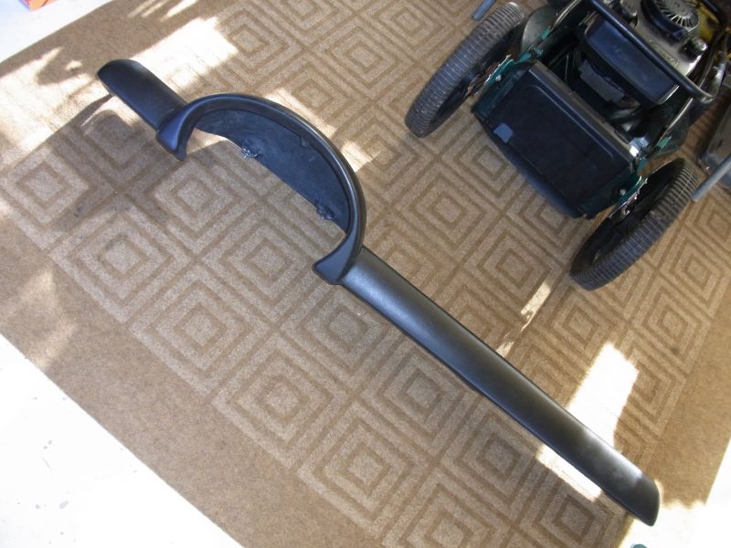 If you have removed the dash from your car, you will definitely appreciate what I have to say. If not, go out and remove it and then reinstall it before you continue reading. He built all of the mounting lugs into his part. Yes, all 8 of them. 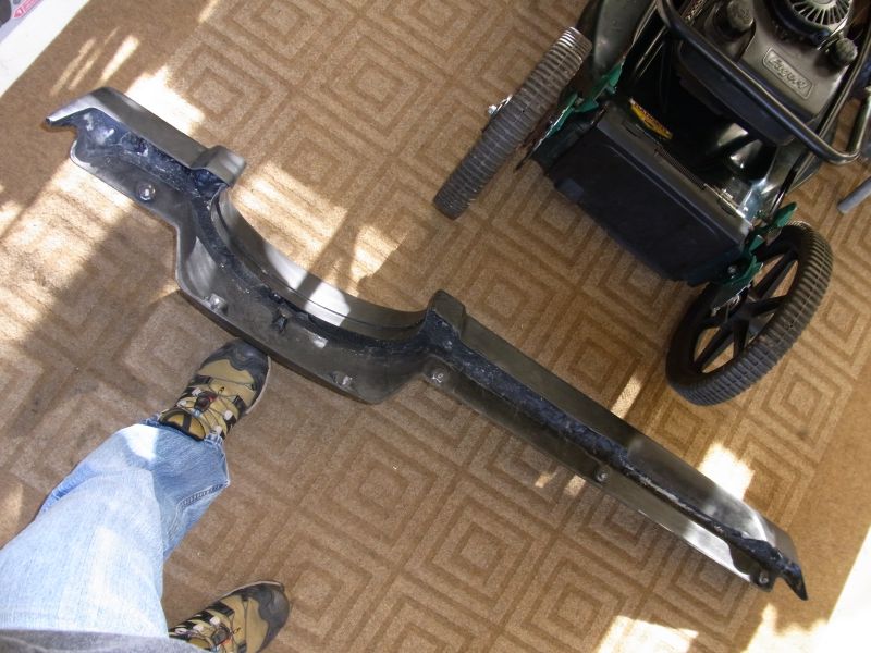 When removing the stock dash I was not sure that it would actually come out because the bolts stick through the vertical and horizontal faces of the sub dash. You have to lift and pull at the same time but there it only moves a short distance before the bolts in the other plane start binding. Anyways, after talking to ruby914 and seeing pictures of his work I was pretty sure that the part would fit but even with his skill I anticipated a bit of wrestling to get it in just because the fit is so stink'n tight. Not the case at all. I put the part in place checked a few holes for alignment, wiggled it a bit and it popped right in place. I had to do some modifications to the sub dash to get the bottom ears of the instrument cluster to fit but the directions in his build thread made it very straight forward. Isn't it cool!! (IMG:style_emoticons/default/first.gif) 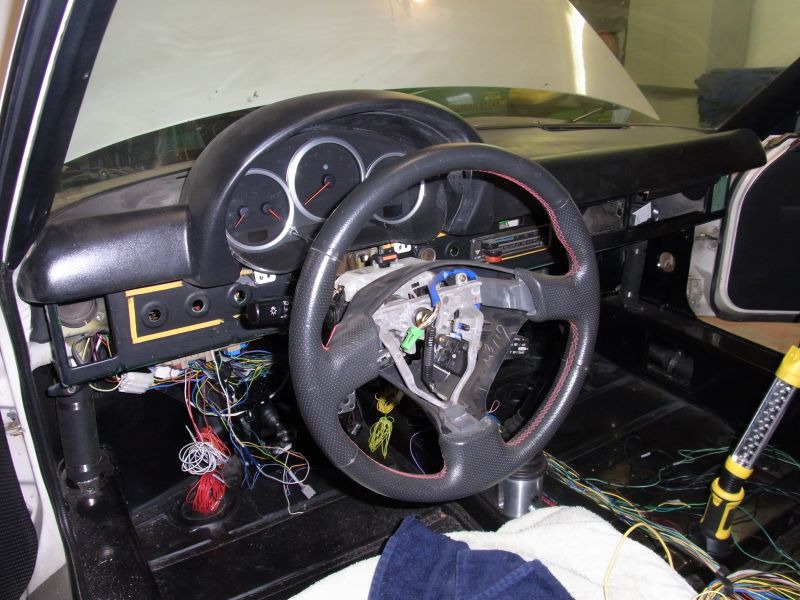 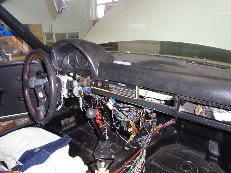 I also did quite a bit of very uninteresting stuff. Mostly organizing wires and mounting relays, switches and other random harness components. I am getting closer to being able to take the harness out again to lengthen and reconnect the wires that I have been cutting to get the harness to match the position of the components. Cheers, Scott |
|
|
|
|
1 User(s) are reading this topic (1 Guests and 0 Anonymous Users)
0 Members:

|
Lo-Fi Version | Time is now: 3rd May 2024 - 03:14 AM |
Invision Power Board
v9.1.4 © 2024 IPS, Inc.