|
|
|
Porsche, and the Porsche crest are registered trademarks of Dr. Ing. h.c. F. Porsche AG.
This site is not affiliated with Porsche in any way. Its only purpose is to provide an online forum for car enthusiasts. All other trademarks are property of their respective owners. |
|
|

  |

| Thorshammer |
 Nov 15 2006, 06:29 PM Nov 15 2006, 06:29 PM
Post
#41
|
|
Senior Member  Group: Members Posts: 749 Joined: 11-November 03 Member No.: 1,335 |
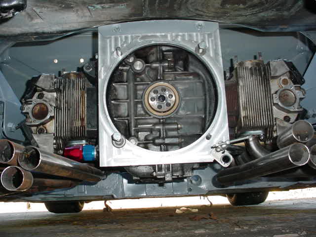 This is the engine and trans attachment plate. It has the proper protrusion and indetation step to center the engine and trans. I had shop CNC this for me. The rear of the engine and the entire transmission is supported by this plate and the two mounting bolts that are in double sheer. The bolts are 10mm Erik |
   |

 
|
| Thorshammer |
Nov 15 2006, 06:33 PM
Post
#42
|
|
Senior Member Group: Members Posts: 749 Joined: 11-November 03 Member No.: 1,335 |
 This is the front side of the same mount. This is the engine side. The crossbar is welded to the chassis spars left to right. I haven't completed it, but this was an area, I thought I could trangulate the chassis a bit. Erik |
|
|
|
| groot |
Nov 15 2006, 06:34 PM
Post
#43
|
|
Dis member Group: Members Posts: 894 Joined: 17-December 03 From: Michigan Member No.: 1,444 |
Eric,
Looks to me (but I might be blind, 'cause I'm looking at the Taylor catalog exploded views of the Hewland) that the Hewland is built with the pinion shaft on top of the mainshaft...... unlike the 901. Did you install yours this way or did you flip the ring and install it like the 901? |
|
|
|
| Thorshammer |
Nov 15 2006, 06:44 PM
Post
#44
|
|
Senior Member Group: Members Posts: 749 Joined: 11-November 03 Member No.: 1,335 |
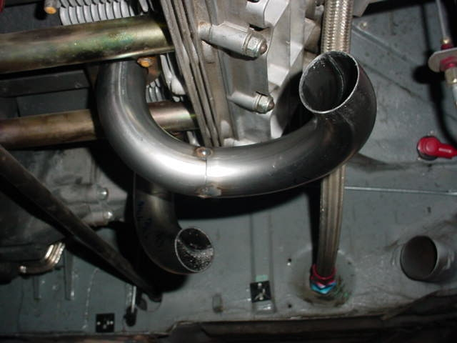
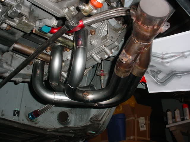 This is mostly of the exhuast, but the detail of the bushing and the shift rod mount is pretty good, This is just a simple delrin bushing , just like the one that goes through the firewall. With a circlip on each side, it can be changed easily, and two bolts remove it from the mounting plate when removing the engine/trans from the car. Erik |
|
|
|
| Thorshammer |
Nov 15 2006, 06:49 PM
Post
#45
|
|
Senior Member Group: Members Posts: 749 Joined: 11-November 03 Member No.: 1,335 |
 This the transmission I am using It was an aircooled Supervee. This linkage is refered to as "Monkey Motion", but I have found it works very well. The early formula Mazda linkage is basically in the same sport, just a little bit forward of where my linkage is on the trans. Erik |
|
|
|
| Thorshammer |
Nov 15 2006, 06:53 PM
Post
#46
|
|
Senior Member Group: Members Posts: 749 Joined: 11-November 03 Member No.: 1,335 |
 I took this to show where the linkage comes through the firewall.Again, I use a very easy to make delrin bushing. The firewall has a drilled hole in it. And the bushing gets a touch of grease to make it slide, or KY, whichever I have laying around in 55 gal drums (IMG:style_emoticons/default/clap56.gif) (IMG:style_emoticons/default/clap56.gif) (IMG:style_emoticons/default/clap56.gif) |
|
|
|
| Cruzing |
Nov 15 2006, 06:55 PM
Post
#47
|
|
Member Group: Members Posts: 214 Joined: 23-October 06 From: San Diego Member No.: 7,082 |
I have a friend that is installing a 911 5-spd trans into his 914, He is turning it upside down, added oil flow ports an pump for circulation and other stuff, I will get more info, but have you guys ever heard of doing that type of thing, he races his 914/6 all the time and wins with it,, I will add photo's later,, if interested...(IMG:style_emoticons/default/smile.gif)
|
|
|
|
| Thorshammer |
Nov 15 2006, 06:55 PM
Post
#48
|
|
Senior Member Group: Members Posts: 749 Joined: 11-November 03 Member No.: 1,335 |
 here is a shot of the entire shift rod. |
|
|
|
| Thorshammer |
Nov 15 2006, 07:02 PM
Post
#49
|
|
Senior Member Group: Members Posts: 749 Joined: 11-November 03 Member No.: 1,335 |
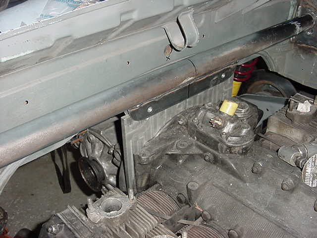
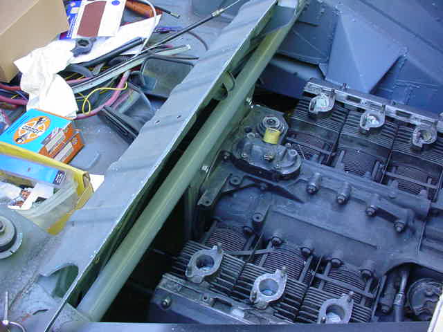 Another shot of the crossbar added to the back of the engine bay. Again, I plan to triangulate this area this winter, but this is where the engine and trans hang from, Well theres a front mount too, but the trans hangs from this mount, there is no rear trans mount as with the 901. I did this so I could change trans gears with limited issues. I just need to disconnect the shift linkage, and loosen the front engine mount, remove the two engine mounting bolts. All of this takes about 4 minutes. Drop the engine down about 3 inches and out comes the entire gearset. it take about 30-45 minutes to change th entire gearstack. When I am hustling. Erik |
|
|
|
| Thorshammer |
Nov 15 2006, 07:10 PM
Post
#50
|
|
Senior Member Group: Members Posts: 749 Joined: 11-November 03 Member No.: 1,335 |
 This is the shift linkage I fabricated. This was one of the most difficult things to do. It is very close to being perfect, but I am going to try some different fore/aft ratios. The linkage is really good. I am using 5/8 APEX joints and welding them wherever possible. This eliminates the apex connection from moving around. if you use AOEX joint for anything, do these couple things. Out a steel slug in the tube they are clamping around, This will prevent the tube from collapsing when the bolts are tightened. Use a fixture when drilling them, and use half moon washers to spread the load out. I used 5/8 chro moly tubing .083 wall for the shift linkage from aircraft spruce. the box is hand fabbed from aluminum, welded by CFR welding, it has delrin bushings front and rear, and uses heim rod ends to control for aft motion of the shift lever. Erik |
|
|
|
| Thorshammer |
Nov 15 2006, 07:15 PM
Post
#51
|
|
Senior Member Group: Members Posts: 749 Joined: 11-November 03 Member No.: 1,335 |
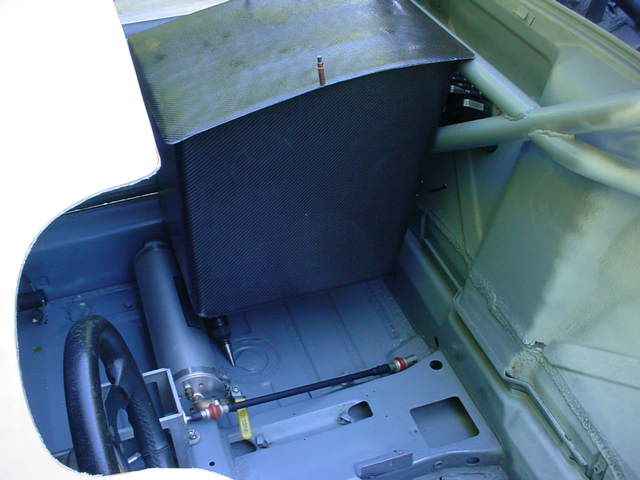
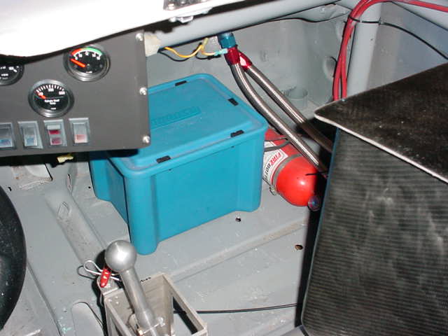
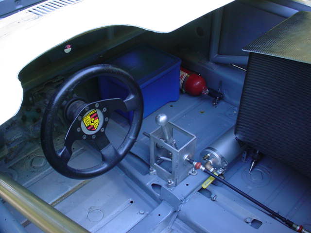 This is a much better picture of the shift box. The handle is cnc'd and the box is a fabbed unit. with the side plates milled for access to the shift lever bolts and adjustments. The box is held to the car with 8mm riv nuts into the sheet metal. I think I would weld bungs into the car if I did this again. The bottom of the shift lever has a heim rod which attaches to the front of the shift box via a short rod, and the for aft adjustment is adjusted at this point. You will also need a large bolt somewhere in the shift rod to allow for left to right rotational adjustments. I use a 14mm bolt and it is double nutted to do this. Erik |
|
|
|
| Thorshammer |
Nov 15 2006, 07:17 PM
Post
#52
|
|
Senior Member Group: Members Posts: 749 Joined: 11-November 03 Member No.: 1,335 |
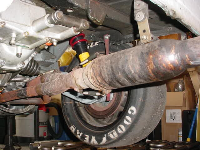
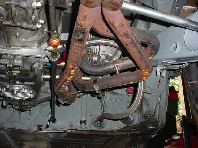
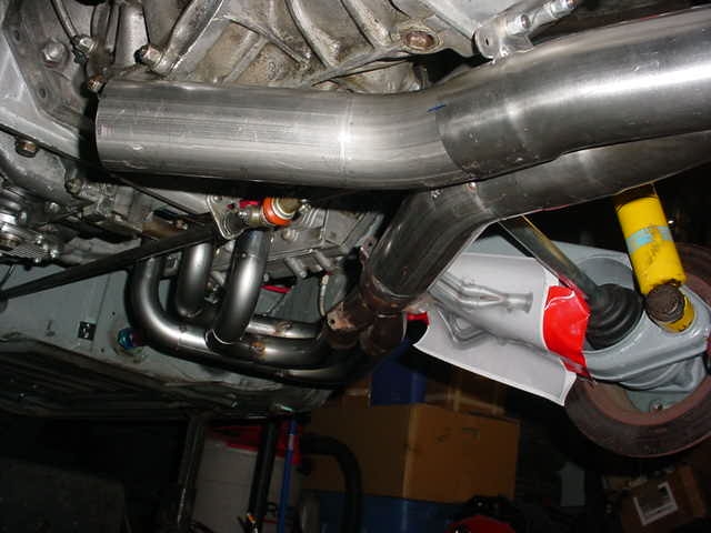 This is really a pic of the exhuast fab, but the trans and linkage is in view. Erik |
|
|
|
| Thorshammer |
Nov 15 2006, 07:19 PM
Post
#53
|
|
Senior Member Group: Members Posts: 749 Joined: 11-November 03 Member No.: 1,335 |
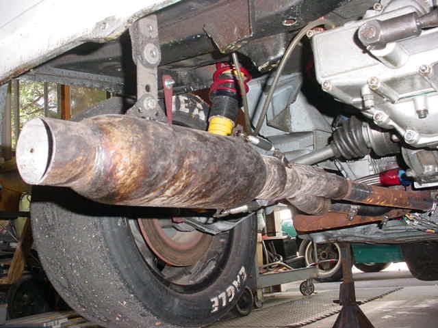 More exhaust, but some transmission Erik |
|
|
|
| Thorshammer |
Nov 15 2006, 07:22 PM
Post
#54
|
|
Senior Member Group: Members Posts: 749 Joined: 11-November 03 Member No.: 1,335 |
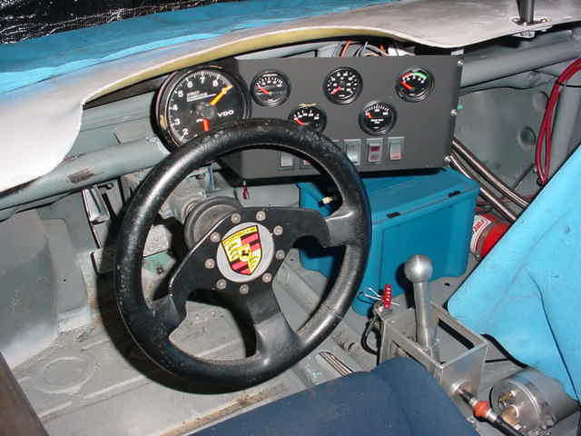 The shift box again |
|
|
|
| Thorshammer |
Nov 15 2006, 07:38 PM
Post
#55
|
|
Senior Member Group: Members Posts: 749 Joined: 11-November 03 Member No.: 1,335 |
 Some more |
|
|
|
| Jeroen |
Nov 15 2006, 08:02 PM
Post
#56
|
|
914 Guru Group: Members Posts: 7,887 Joined: 24-December 02 From: The Netherlands Member No.: 3 Region Association: Europe |
Eric, thanks for sharing these pics
Any chance of a clearer shot "inside" the shiftlever housing? |
|
|
|
| Thorshammer |
Nov 15 2006, 08:07 PM
Post
#57
|
|
Senior Member Group: Members Posts: 749 Joined: 11-November 03 Member No.: 1,335 |
No,
I'm embarrased, but the car is at my mother in laws garage. I have too much work here. Its killing me. Those are the only photos I have at this time. Erik |
|
|
|
| Brett W |
Nov 15 2006, 11:41 PM
Post
#58
|
|
Advanced Member Group: Members Posts: 2,856 Joined: 17-September 03 From: huntsville, al Member No.: 1,169 Region Association: None |
Kevin you need to flip the tranny. This will allow you to lower the engine and tranny. Right now the engine has to sit relatively high. If you flip the tranny you can get about 3in (If I remember right). Would allow for better axle alignment on super low race cars, plus it leaves all of your linkage and such clear of the exhaust.
|
|
|
|
| groot |
Nov 16 2006, 06:41 AM
Post
#59
|
|
Dis member Group: Members Posts: 894 Joined: 17-December 03 From: Michigan Member No.: 1,444 |
Great idea, but it ain't legal... and the starter will be in the way of the header.
From the GCR: 6. Motor mounts of alternate design and/or material may be used, but there shall be no change to the engine’s fore and aft or vertical location. Transverse engine vehicles may rotate the engine about the crankshaft centerline to align axles/CV joints. On rear engine/rear drive cars the engine/drivetrain may be relocated vertically upward, to a maximum of one (1) inch, to allow alignment of suspension and driveline components. No other engine rotation or relocation is permitted on any car. |
|
|
|
| Brett W |
Nov 16 2006, 11:17 AM
Post
#60
|
|
Advanced Member Group: Members Posts: 2,856 Joined: 17-September 03 From: huntsville, al Member No.: 1,169 Region Association: None |
DOH!!! Damn rules.
|
|
|
|
|
1 User(s) are reading this topic (1 Guests and 0 Anonymous Users)
0 Members:

|
Lo-Fi Version | Time is now: 7th May 2024 - 06:09 AM |
Invision Power Board
v9.1.4 © 2024 IPS, Inc.