|
|
|
Porsche, and the Porsche crest are registered trademarks of Dr. Ing. h.c. F. Porsche AG.
This site is not affiliated with Porsche in any way. Its only purpose is to provide an online forum for car enthusiasts. All other trademarks are property of their respective owners. |
|
|

  |

| BMXerror |
 Aug 22 2008, 04:44 PM Aug 22 2008, 04:44 PM
Post
#71
|
|
Senior Member  Group: Members Posts: 1,705 Joined: 8-April 06 From: Hesperia Ca Member No.: 5,842 |
Well, after the side track with the engine I got back on track to do the front anti-roll bar. The car lacked any anti-roll bars from the factory, and I feel that that's what cost me the most time at last years Nite AX... well, that and my lack of skill! (IMG:style_emoticons/default/biggrin.gif) So I set to work. After looking at what was available from Tarret and Weltmeister for $470, I figured I could fabricate some for cheaper. I started with the 1" hollow bar sold by HRP world (http://www.hrpworld.com/index.cfm?form_prod_id=216,212,363_1424&action=product) , and the accompanying splined aluminum arms (http://www.hrpworld.com/index.cfm?form_prod_id=216,212,363_1428&action=product)
For starters the arms were too long to even FIT in the wheel well. There would've been serious tire clearance issues, so I had to cut them down considerably. I ended up taking almost 7 inches off of the end. There also aren't any holes for drop links to attach to, so I had to make those. I knew I didn't want slots as they are rather weak, but I figured that the arms were so thick that I could get away with two staggered rows of adjustment holes. Very long story short, I ended up with 28 adjustment holes in 1/4" increments. When I say they are 1/4" increments, I mean that from center of the bar to center of the drop link hole. I actually trigged out every hole so that the center to center distance would be right. This doesn't mean anything right now, but when I learn how to calculate spring rates of these bars, I'll be able to do so accurately. 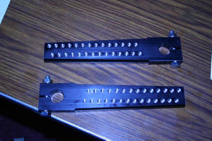 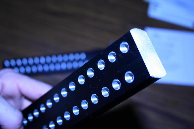 So I set the part up in a CNC mill and located off of the splined hole, wrote a quick CNC program to spot drill the holes, and then just edited the same program for the drilling and tapping operations. They are tapped M8 X 1.00. A more experienced guy at work did help me with the setup a bit, and I'm very grateful. I didn't even ask, he just offered! This here's to you, UB. (IMG:style_emoticons/default/beerchug.gif) Oh, forgot one thing. I threaded the arms because I wanted to make them hug the inner wheel well as much as possible, and I didn't want bolts and nuts sticking out on the back side. Also, it will make adjustment easier at the track, as you won't have to worry about blind-threading a nut. Mark D. |
   |

 
|
| BMXerror |
Aug 22 2008, 04:46 PM
Post
#72
|
|
Senior Member Group: Members Posts: 1,705 Joined: 8-April 06 From: Hesperia Ca Member No.: 5,842 |
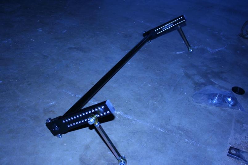
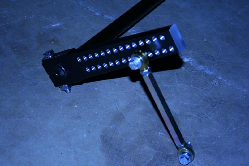
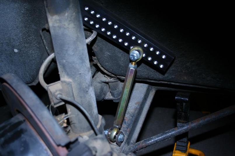
For drop links I simply purchased the Weltmeister units so that I didn't have to bother building my own up from rod end components. Normally I wouldn't mind, but I was coming down to the wire on time, so I did it the quick way and probably spent a little extra cash in the process. I did, however, replace the SAE hardware with metric, because I try to keep it all metric on my car. I couldn't do that on the turn buckles, though. (IMG:style_emoticons/default/dry.gif) The M8s were actually a closer fit in the sleeves than the 5/16" bolts that came with the drop links.
  Mark D. |
|
|
|
| BMXerror |
Aug 22 2008, 04:59 PM
Post
#73
|
|
Senior Member Group: Members Posts: 1,705 Joined: 8-April 06 From: Hesperia Ca Member No.: 5,842 |
I got the bearings from the Big Bearing Store online, and just used the pressed steel housings. The housing is flared to hold the bearing, and that flare is a little over 2-1/4" DIA. So all I did is hole saw a 2-1/4" hole in the wheel well and drill two holes for mounting bolts. It sounds cheesy, but it seems to work well. What I had in mind was that when you tighten the bolts it would compress flare of the bearing housing into that 2-1/4 hole, making that large hole the load bearing surface, and not the two small bolt holes. This theoretically eliminates the need for any further reinforcement in the area, at least with the relatively soft bar. I've run one AX with it as well as some spirited canyon driving, and there seems to be no signs of cracking or excessive stress. Sorry, I don't have any pictures of the bearings from the back side. I was in a serious rush and actually lifted the car, figured out how the bearings should go in there, laid it out, drilled the holes, drilled the bolt holes, measured for the bar length, set the car down and cleaned up in an hour and a half. I didn't really think to snap any shots.
Problems: 1. In my rush of laying the bearing holes out without the gas tank in, I didn't think to make any consideration for the height of the bar, as it relates to the bottom of the gas tank. Once the bar was in and the gas tank was reinstalled there was the tiniest little drag on one side of the bar (I was looking for it by then as I figured out later that that might be a problem). A couple minutes of "adjustment" on the gas tank with a sledge hammer and a block of wood cleared that problem right up, (IMG:style_emoticons/default/smash.gif) but it's still VERY close in there. If I go to a 1-1/4 bar later, something else will have to be done. 2. The bearings I bought were about a 1.0002" bore, and the bar miced in at about 1.0006. I figured it easier to hone the bearings than knock all the paint off of the bar and hope I wouldn't have to grind it, so I went ahead and honed the bearings. I still can't slide the bar all of the way through, but the part that needs to fit, fits, and fits tight! 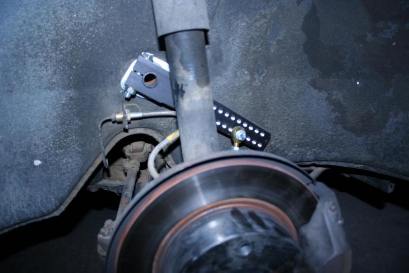 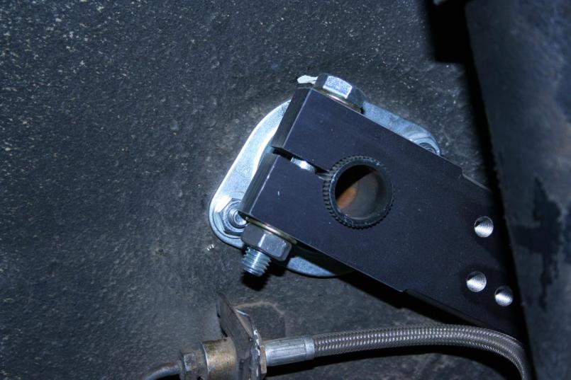 Mark D. |
|
|
|
| BMXerror |
Aug 22 2008, 05:08 PM
Post
#74
|
|
Senior Member Group: Members Posts: 1,705 Joined: 8-April 06 From: Hesperia Ca Member No.: 5,842 |
Right now the adjustment is pretty well on the loose side. You see, before I didn't like the body roll, but I thought the balance of the car front to back was pretty good, and I figured that ONLY adding a front sway bar to the thing would upset that. As a result, I bought a rear coilover kit from Paragon Products with 200 lb springs. Unfortunately, I didn't realize that that kit wouldn't work with the KYB struts that are in there. I called E-shocks to get some Koni Yellows 3 day shipped out here, and put it on credit. This was on last Monday when I was supposed to race on Saturday! Well the shocks never showed up, and I was never charged for them. I called earlier this week and they have no record of the order! (IMG:style_emoticons/default/headbang.gif) Oh well, I shouldn't have gone into debt for my hobby anyways. Back to the tech side of things, though, the anti-roll bar did make the car oversteer a BIT more, but once I got used to it, I rather liked it! It handles like a Porsche now! I still think we could get a little more out of the front tires, but right now, what I'm getting from the lack of body roll MORE than outweighs the slight lack of balance.
 Mark D. |
|
|
|
| BMXerror |
Aug 22 2008, 05:19 PM
Post
#75
|
|
Senior Member Group: Members Posts: 1,705 Joined: 8-April 06 From: Hesperia Ca Member No.: 5,842 |
So, I got basically all that Tarret and Weltmeister sells for about $470. What was the final price tag of mine?
Arms: $95 Bar: $96.28 with 2 day shipping Drop links: $105.98 from Paragon Products Bearings: $28.31 Hardware: $24.25 Total: $349.82 That plus a few late hours at the machine shop and in the garage. I consider it time well spent. The results: Last year! 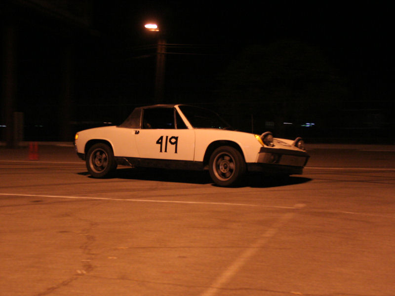 Oh my! This year! 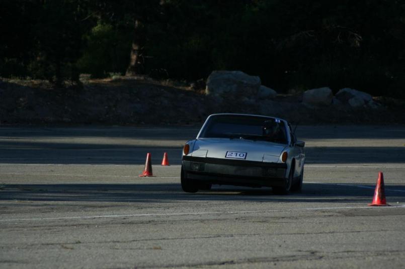 The bar went in Tuesday night, my brother and I AXed it at Snow Valley on Saturday and took 5th and 3rd respectively! I was super stoked, and more importantly, I think I gave my brother the autocross bug! (IMG:style_emoticons/default/happy11.gif) Mark D. P.S. God! I didn't mean for that to be such a novel! Sorry. |
|
|
|
| BMXerror |
Oct 26 2008, 05:09 PM
Post
#76
|
|
Senior Member Group: Members Posts: 1,705 Joined: 8-April 06 From: Hesperia Ca Member No.: 5,842 |
Well, this is the first work I've done since Allen died. This was another typical example of how my car has come together the past couple years. I had an idea of something that could be better, I came up with a solution, ran to tell him to show him how smart I am, and then he came up with a way better way to do it! (IMG:style_emoticons/default/biggrin.gif) Well, not completely, but we did bounce ideas off of each other a lot.
Here's the problem. There was a lot of slop between the rear lever thing on the transmission (highly technical terminology, I know) and the input shaft for the gear selector. This was resulting in about 1/4" of play just at the end of that lever. Multiply that up the long shift lever, and it turns into a lot of forward/back slop. So what we came up with was to drill the rivet out of that rear lever and use cone screws instead. Well, when I finally got to it a couple weeks ago, I drilled out the rivet and found out that the hole in the input shaft was much larger than the rivet, which caused the slop. I don't know if there's more that's supposed to be in there or not, but I didn't like it one way or another. This also meant that cone screws alone wouldn't work. I had to machine an aluminum sleeve to press in that hole in the input shaft and reduce the diameter so the cone screws would actually have something to press up to. I swore I took a picture of the sleeve, but I can't find it! (IMG:style_emoticons/default/mad.gif) First step was to drill out the rivet and remove the lever. After that I had to drill and tap the lever for the cone screws. M8 X 1.25 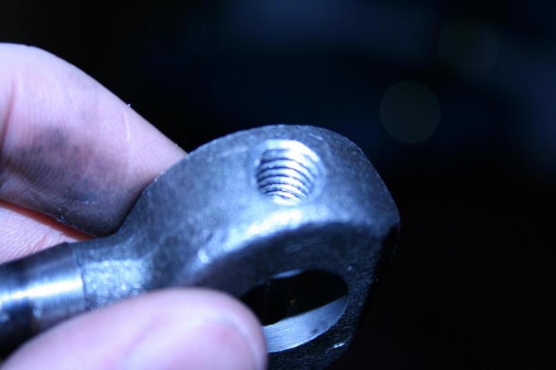 With the cone screws installed. They both compress into a common aluminum sleeve and is press fit into the input shaft. The press fit came out perfect. Not too hard to tap in, but certainly not coming out! 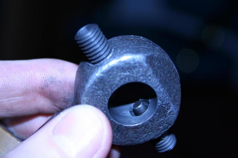 The result is a very tight fit on the input shaft and reduced slop in the shift linkage. 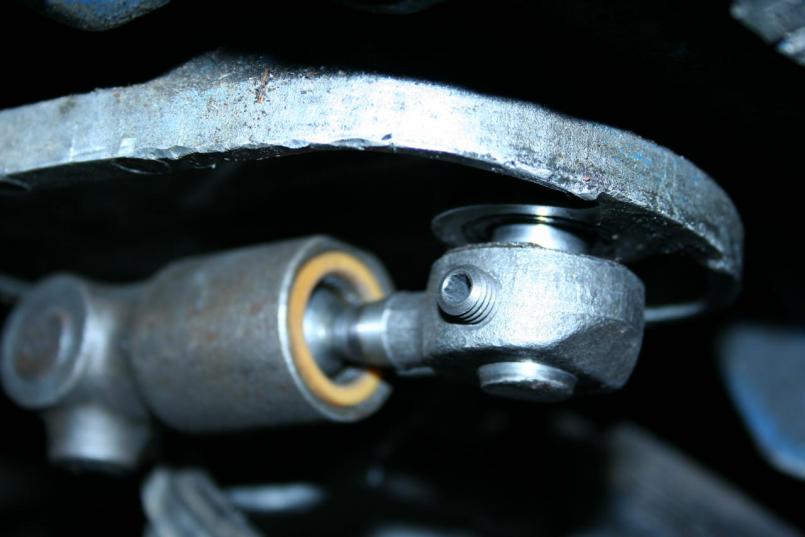 The results were pretty satisfactory. There wasn't as much reduction in the forward/back play as I had hoped, but there is a much more positive feel when selecting a gear. You KNOW when it's in and when it's out, as well as when it's starting to mesh. A while back ago I also made a similar aluminum sleeve to go between the transmission case and the rear bushing. I drilled the case out to 7/8" and machined the sleeve to be pressed in (If I had to do it again I wouldn't drill the case). This makes the rear bushing fit super tight. You actually have to take the sleeve out, press the bushing into it with a vise, and then tap the whole assembly into the case with a hammer..... it's not coming out, though. This reduced the side to side play considerably. The combination of these modifications, in addition to the Weltmeister short shift kit that was on there when I got the car makes for a fairly nice shifting 914.... It still shifts like a 914 though. (IMG:style_emoticons/default/biggrin.gif) Anyways, no money as of late, so this is the kind of stuff I've been doing... Well, that, and planning out the roll cage that I hope to build next year. It'll be tough without the other half of my brain, though. (IMG:style_emoticons/default/sad.gif) Miss you bro. Mark D. |
|
|
|
| carr914 |
Oct 27 2008, 06:46 AM
Post
#77
|
|
Racer from Birth Group: Members Posts: 118,556 Joined: 2-February 04 From: Tampa,FL Member No.: 1,623 Region Association: South East States |
Mark, good to see you back working on the car. Your brother would be proud and he's probably looking over your shoulder.
T.C. |
|
|
|
| BMXerror |
Jan 3 2009, 09:21 PM
Post
#78
|
|
Senior Member Group: Members Posts: 1,705 Joined: 8-April 06 From: Hesperia Ca Member No.: 5,842 |
So this is what I was up to this week. See, last weekend I was asking my dad questions about oiling systems for the engine I'm designing (top secret!), and somewhere in the conversation he said something about having a safety wired into the thing to where when it loses oil pressure it kills the ignition. I thought, "Hey! That'd be a really cool thing to do SOMEDAY." That was last weekend, and 'someday' turned out to be this weekend! (IMG:style_emoticons/default/biggrin.gif) I got to thinking while taking a cruise in the 914 that there's already a switch that kicks on upon VERY low oil pressure, for the idiot light! Well, my idiot light doesn't work, but I do have the dual sender for my oil pressure gauge. So we started figuring it out.
I first had to decide if the range was right for the pressure switch. Namely, would it kick off at a low enough pressure that it wouldn't interfere with daily driving, but a high enough pressure that no major damage would occur before it shut off. I looked up the VDO part # for the dual sensor and found out that the light is supposed to turn on at 11.4 PSI. It sounded about right, so I figured I'd go for it. There was also a 7.4 sender in case the shut-off interfered a lot. This made me think it was possible, so my dad and I went about drawing some wiring diagrams. He's done automation controls on all kinds of stuff for years, so he was a big help on the relay logic.... Oh, who am I kidding. He just drew it up and I watched! (IMG:style_emoticons/default/biggrin.gif) What I wanted was for it to interrupt the lead from the ignition loom to the + side of the coil, light an indicator light, and trip a holding contact to hold the thing off so that you couldn't restart the engine until you reset a manual override. The holding contact is basically a feature to make sure you acknowledge the problem before trying to restart the engine. I'm not gonna bother trying to explain all the relay logic in text because it's just confusing as hell, but I got all that to work on one 8 pin relay. The only major thing that got changed in the design was that instead of cutting the power to the coil, I ended up interrupting the control to the rear relay board. This is the wire that goes from terminal 8 on the fuse box to terminal 8 on the 14 pin connector in the rear. I knew about this wire because it shorted out on me once and I had to trace and replace it! Without power to this wire, nothing runs! No fuel pump, no ECU, no injection, no ignition. I chose to do it this way mainly because it meant I didn't have to run wires for the coil all the way from the back to the dash (where the relay is) and back again to the coil. It was all just done in the dash from the fuse box. As an added bonus, though, if it ever does kick off on low oil pressure, it won't still be pumping fuel to a fireless engine. There's a manual override switch right next to the starter switch (toggle right now, but I'm gonna change it to a momentary). You hold the manual override up with the starter switch to start the car and then let it go once it starts. This override shuts the safety circuit off while the engine is at rest (with no oil pressure) and allows the engine to get fuel and spark to start. It also shuts the oil pressure light off. Once I get the momentary switch in, the safety circuit will switch on as soon as you let go of the switch. Right now it's just normally overridden, and you just switch it on after the car starts. Well, enough talk. Let's get to pictures. This is the relay I used. It was like 8 bucks at Radio Shack, and the base for it (with all the solder in connections) was in my dad's stash! I made a little bracket to tuck it up under the dash. It works, but I'm not real proud of it, so you're not getting a picture of that! (IMG:style_emoticons/default/biggrin.gif) 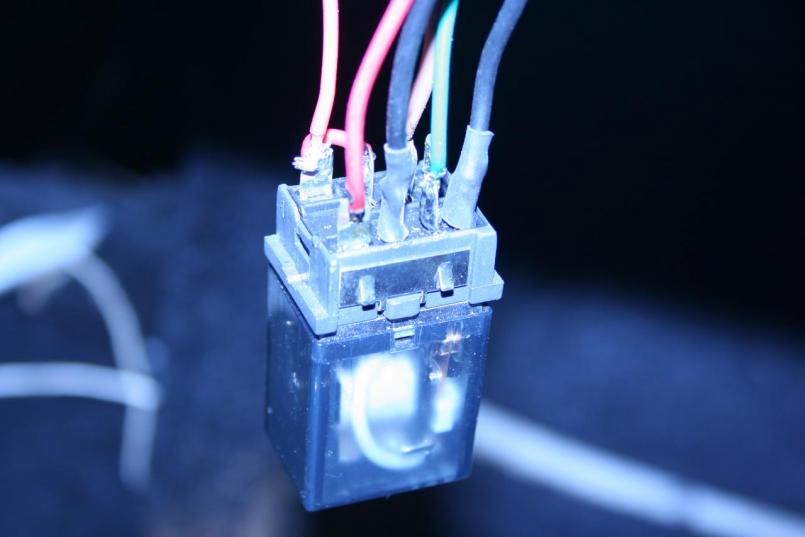 This is not really relevant to the story, but I seriously need to work on my organizational skills when I'm actually in the middle of a job...... That and the picture is fuzzy! (IMG:style_emoticons/default/dry.gif) 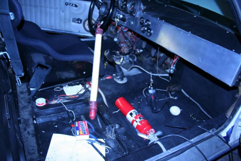 Mark D. |
|
|
|
| BMXerror |
Jan 3 2009, 09:48 PM
Post
#79
|
|
Senior Member Group: Members Posts: 1,705 Joined: 8-April 06 From: Hesperia Ca Member No.: 5,842 |
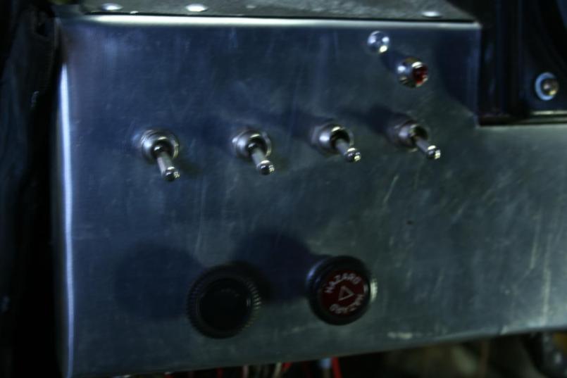
This is the dash before startup. All switches down. The far right switch is the override, and the light above it is the warning light. Down means it's overridden and it gets flipped up after the car is started.
 This is the panel in a 'fault' condition. The ECU switch (second from the left) is up because the car was running, but I took the sensor wire and grounded it to test it, and it killed the engine immediately. Note that the override switch is up (off), meaning the safety circuit is active, and the light is on, meaning that the switch has tripped on low oil pressure (or grounded sensor wire). This will actually be reversed when I make that a momentary switch. It'll normally be down, except when you hold it up during startup to override and allow the engine to start. 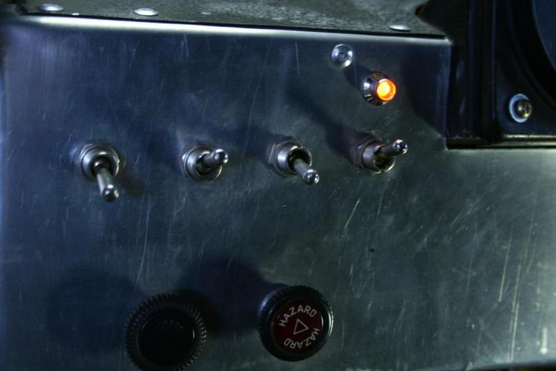 Well, that's it! I took it for a test drive and really bogged it off the line a few times to see if it'd trip off under normal (or close to normal) conditions, and it didn't. The only time it when off was when I flat out stalled it trying to bog it, and then I heard the relay click and the light went on. I think the response of the pressure switch is a little slow, but even so, if I broke an oil line on the track or something, it should be fast enough to save the major components of the engine, if not the bearings. The total cost was under $30 dollars. That includes some extra pieces that I ended up not using, but doesn't include the pressure switch which I already had, and a couple connectors and stuff. If it works ONCE, it's more than paid for itself! Thanks for reading.... GOD That was long! (IMG:style_emoticons/default/beerchug.gif) Mark D. :edit: full credit goes to my dad on this one. It was his idea in the first place (said he saw it on an old Clarke forklift in the early 80s) and I would've been lost trying to design it without him. Thanks pop! |
|
|
|
| PeeGreen 914 |
Jan 3 2009, 10:25 PM
Post
#80
|
|
Just when you think you're done...wait, there is more..lol Group: Members Posts: 10,219 Joined: 21-September 06 From: Seattle, WA... actually Everett Member No.: 6,884 Region Association: Pacific Northwest |
Nice work. Keep us posted how everything works (IMG:style_emoticons/default/beerchug.gif)
|
|
|
|
| BMXerror |
Mar 29 2009, 10:28 PM
Post
#81
|
|
Senior Member Group: Members Posts: 1,705 Joined: 8-April 06 From: Hesperia Ca Member No.: 5,842 |
Well, no pictures on this post because it's nothing really creative. More of an 'open your wallet real wide and bolt the dollars to your car' kinda things. I got my Koni yellows for the rear, and was finally able to mount my coilover kit that I bought last JULY!
Previously I had KYB rears that were on the car when I got it, and they were rather worn out. Also, I think they were close to stock ride height, because the car was kinda 'stinkbug' before. If you were driving on a strait road and gave the wheel a wiggle, it would wag it's tail at you for a little bit after you straitened the wheel out. It took time for it to settle out. I'm pretty sure this was mostly a high roll center problem. When I added the front swaybar, it drastically improved the overall handling of the car by eliminating body roll, but it made the thing very tail happy even with the sways at their softest setting. I figured this would be the case, as I built the swaybar with the rear coilovers and 200 lb springs in mind. I just couldn't afford to do both at once. So anyways, my tax return came just in time for Paragon Products to have a 15% off sale on all Koni products ('till July, if anybody is interested). It was a match made in heaven! So I ordered those, as well as a pistol type pyrometer last week, and left work early to mount the shocks on Friday. I lowered the rear by 5/8" from where it was before, giving me about 5-3/8" at the rear doughnuts. Lowering the roll center did a LOT! It actually sits like a Porsche now, instead of a mid '60s hot rod! I set the shocks right in the middle of their dampening adjustment as a place to work from, but it really ended up being about perfect! I also stiffened my swaybar a full two inches on the arm to balance it out. I was acting as pit crew for an overheating Lister at the speedway yesterday, so I didn't get to really test the 914 till today, and BOY what a difference. The front end is right where you point it, and the back end stays in the back! (IMG:style_emoticons/default/biggrin.gif) I brought out my new temp gun and sorted out tire pressures in a way I've never done before. I found a tad bit of understeer in the canyons which was easily alleviated with a 1/4" swaybar adjustment on the side of the road, and now it seems just right. Of course, I won't know for sure until I can really cut loose on an autocross course, but I think today's little shakedown session got me pretty close to dialed in! I'm very happy that the front and rear projects came together as well as they did. This was something I planned about a year and a half ago, and the results are awesome! Incidentally, you get really funny looks from people when you stop at a turn out and break out the pyrometer, a pressure gauge and a clipboard and do a full write-up on the side of the road! haha... And the cop didn't even want to ask what I was doing! I wish I had a picture of the look on her face when she walked up to my window and saw the aluminum dash, no passenger seat, and me tightening my 5-points! (IMG:style_emoticons/default/WTF.gif) (IMG:style_emoticons/default/lol-2.gif) Priceless! I'm gettin' close to ready for May 3rd! Have a (IMG:style_emoticons/default/beer3.gif) ! Mark D. |
|
|
|
| BMXerror |
Oct 17 2009, 06:21 PM
Post
#82
|
|
Senior Member Group: Members Posts: 1,705 Joined: 8-April 06 From: Hesperia Ca Member No.: 5,842 |
Well, since the rear suspension is well sorted now, I decided to get into the front. I happened across the pictured upper strut mounts, and decided that it was a good time to take out the stock mounts and reverse engineer them (I'm designing adjustable mounts). However in the process of trying to get the rusty struts out of the rusty mounts, I mushroomed the thread on the right side with my BFH. So the new mounts got new Koni yellows to match the rear. (IMG:style_emoticons/default/aktion035.gif)
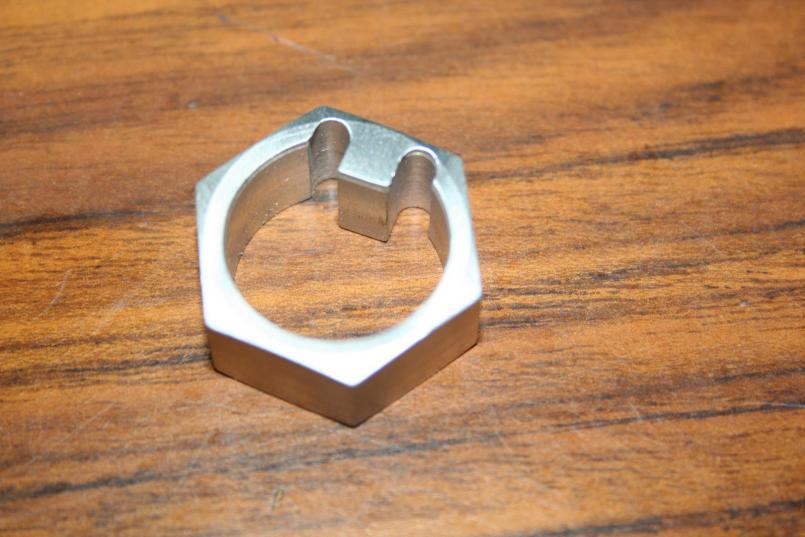
In addition to all that, I got new tires all the way around as the Kumhos that I was running were rather hard and blistered. Dunlop Direzza Sport Z1 Star (Inhale) Specs, all the way around. So yesterday, I figured it'd be a good time to drop the ride height, equalize the camber, and do a four wheel alignment. The took about 8 hours, considering I've never done it before, and the frame is a bit tweaked, and EVERYTHING was out of adjustment. But the results look promising. 2 degrees negative camber in the rear, 1.5 in the front. I'm trying to put a few gentle miles on the tires before really pushing them, but I'm autocrossing next weekend, so we'll see how it works. The only thing unusual about this setup is the custom hardware that I had to machine to work with the new mounts. These 'retainers' are basically a 22mm nut no threads and a key cut in them. I tried making them out of aluminum, but that didn't work so well. So I went back and redesigned them to give them a little more meat, and made them out of steel. New mounts. Attached thumbnail(s) 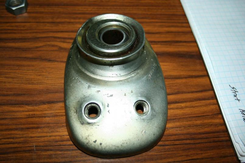
|
|
|
|
| BMXerror |
Oct 17 2009, 06:23 PM
Post
#83
|
|
Senior Member Group: Members Posts: 1,705 Joined: 8-April 06 From: Hesperia Ca Member No.: 5,842 |
First retainer.
 Second retainer. 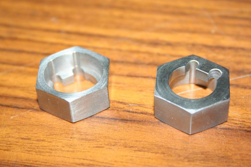 Mark D. |
|
|
|
| BMXerror |
Oct 17 2009, 06:26 PM
Post
#84
|
|
Senior Member Group: Members Posts: 1,705 Joined: 8-April 06 From: Hesperia Ca Member No.: 5,842 |
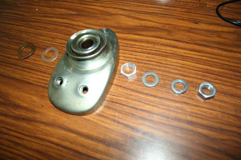
This was my original plan for hardware. I only ended up using about half of that.
 Mounted and adjusted. You can see how far over and back it's adjusted, but the other side is pretty much centered for the same amount of camber. A little frame tweaking, me thinks. Note the adjustment key on top of the shock. Please ignore the dirty ass sheet metal with 4 different paint jobs on it. 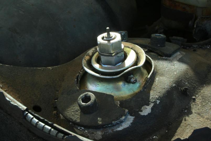 Mark D. |
|
|
|
| BMXerror |
Jan 26 2011, 11:07 PM
Post
#85
|
|
Senior Member Group: Members Posts: 1,705 Joined: 8-April 06 From: Hesperia Ca Member No.: 5,842 |
*If you don't want to read my lame story, skip the next 4 paragraphs*
Good lord! I can't believe it's been a year and a half since I posted any progress... haven't really made much, is why. Where to start?.... Well, I started autocrossing with SCCA in may of '09 and quickly learned how slow my car and myself really are amidst a competitive group. As discouraged as I was, I realized that that's where I needed to be to improve my skills, both on the driving and preparation side. However, I ended up focusing a lot of my money and efforts into track time, and little got done with the car. About May of 2010, the D-jet system really started getting bad. It was never really great with the modified engine, but the system started deteriorating rapidly to where it barely wanted to run. I decided to park it before it cost me an engine. I quickly realized I was faced with two options. Either spend to rebuild the ignition and injection systems and live with D-jet for even longer, or bite the bullet and go to SDS as I've wanted to do for years. Well, there was no cash for that. I was trying to buy a house, and my commuter car blew an engine shortly thereafter. However, in August I was able to find a brand new SDS EM4-4F system (exactly what I wanted) on eBay for cheap. It was a guy in Australia who bought it for a project that never got that far. With shipping back to the US I paid $1140. Plus I had to ship it to SDS and have some rework done for some of the options I wanted, as well as a V17 chip upgrade. That was another $388. All in all, I figure I saved about $500 on a fully loaded system. Of course, as life goes, I got my house the very next month, and for a while it was very hard to find time and money to put into the install. However, I was try to spend one extra night a week in the machine shop building the brackets and stuff I need for the sensors and injectors. So anyways, in the past 4 or so months, this is what I've come up with. The first custom part I machined is a mount for the TPS. Luckily, the 'D' pattern on the TPS is the same as the stock shaft. The shaft did need to be cut shorter, which took me about two minutes with an angle grinder and a cutoff wheel. The hard part was that the TPS plug is turned 90 degrees from the stock location towards the back of the engine. With the bell housing there, it gets a little tight to plug the loom in. So careful measurement had to be made to make sure everything would fit. What I came up with was a two piece design that consisted of a machined block that mates to the TPS, and a sheet metal 't' that flips it 90 degrees and mounts the assembly to the stock TB. 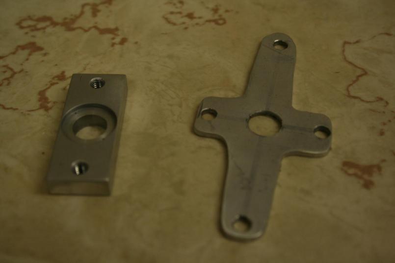 TPS brackets. You can see that the sheet metal part was all done by hand. It's functional. 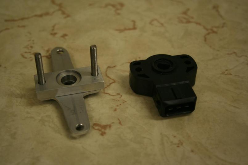 Assembled TPS mount alongside new TPS. You SDS guys will be familiar with that part. 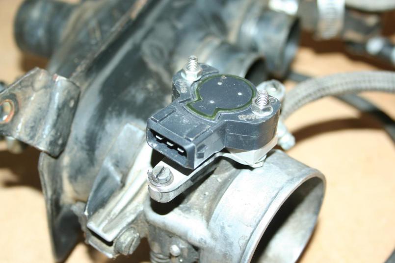 Installed. Mark D. |
|
|
|
| BMXerror |
Jan 26 2011, 11:08 PM
Post
#86
|
|
Senior Member Group: Members Posts: 1,705 Joined: 8-April 06 From: Hesperia Ca Member No.: 5,842 |
One more.
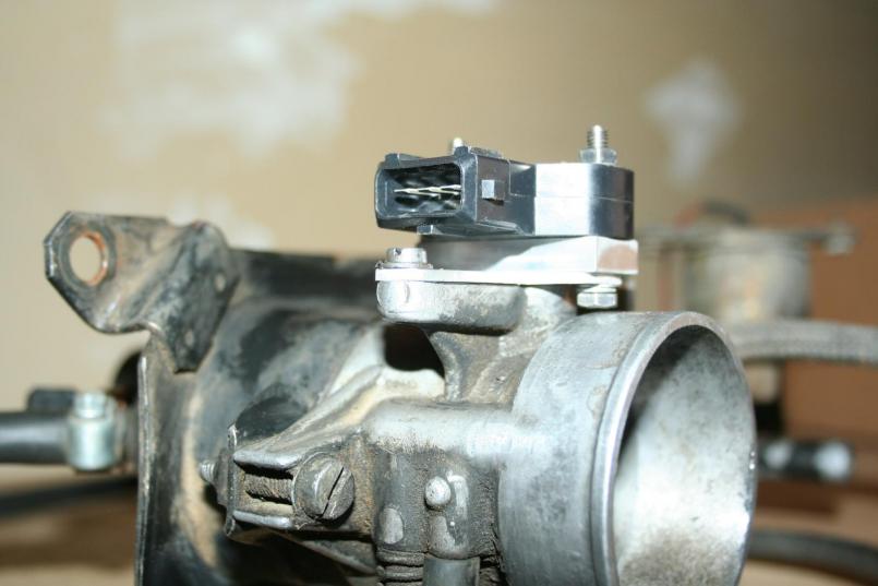 Just enough clearance between that screw and the plug that goes below it. Mark D. |
|
|
|
| BMXerror |
Jan 26 2011, 11:15 PM
Post
#87
|
|
Senior Member Group: Members Posts: 1,705 Joined: 8-April 06 From: Hesperia Ca Member No.: 5,842 |
Since I'm going to crank fired ignition, another thing I had to make was a blockoff plug for the distributor bore. This was just time spent in the machine shop. I found the o-rings at McMaster Carr. I got a compound of rubber that's supposedly rated up to 400 degrees fahrenheit and oil resistant.
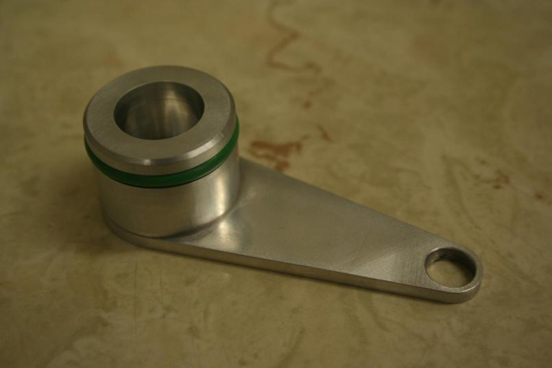 Not much to say about this part except if I do another I'm gonna leave more material around the bolt hole if I have to do another. That was a reverse engineering mistake. I.E. I don't know how to measure a stud. (IMG:style_emoticons/default/blink.gif) (IMG:style_emoticons/default/slap.gif) 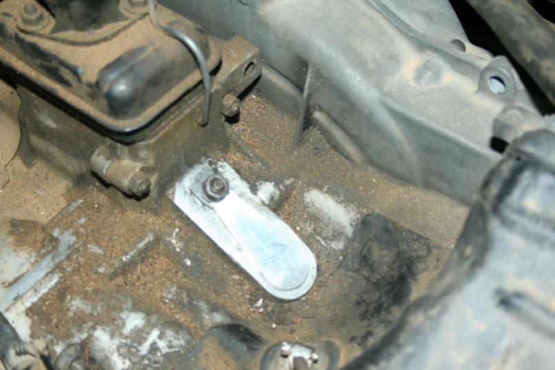 Installed. Don't worry. The engine will get cleaned up before I put it back in. The fit in the bore is almost orgasmic, BTW. (IMG:style_emoticons/default/smile.gif) Mark D. |
|
|
|
| BMXerror |
Jan 26 2011, 11:28 PM
Post
#88
|
|
Senior Member Group: Members Posts: 1,705 Joined: 8-April 06 From: Hesperia Ca Member No.: 5,842 |
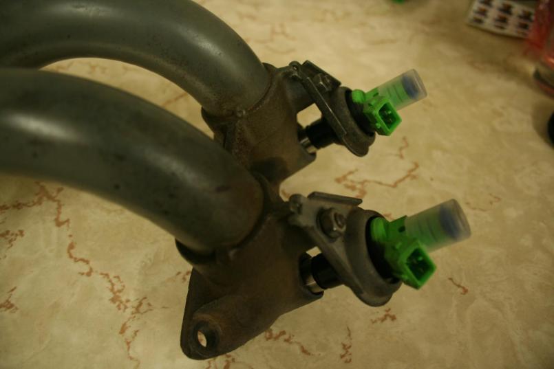
Originally, when I decided that I wanted to go to SDS, I was just planning on using the stock D-jet injectors. However, since I bought a system from a private party, he had ordered injectors with it. He bought the Ford style 440cc 'Green Top' injectors, like so.
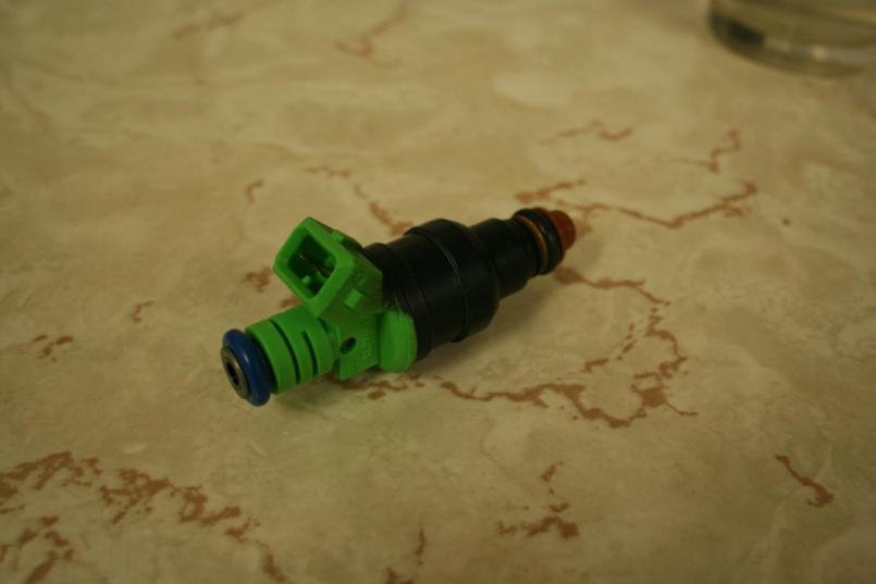 Even though it's overkill for the engine that's in the car right now, I decided to go ahead and install these. Two main reasons: I didn't want to change the injector plugs on the loom, and then have to change them back when I had enough engine that required bigger injectors. These are a standard size, and I can get them in many different flow rates. Also, they're new, and it's always best to use good components, even though there was no known problems with the old injectors. The way I decided to accomplish this is to bore and sleeve the manifolds to accept the new injectors, use the existing clamp, and machine port adapters for the backside (still in process). 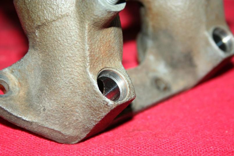 Manifold bored and counterbored to accept the sleeves. The fixturing on this part was a little interesting because the injectors rest at a 80 degree angle from the gasket face. Bore tolerance was .0005 for the press fit. Mark D. |
|
|
|
| BMXerror |
Jan 26 2011, 11:34 PM
Post
#89
|
|
Senior Member Group: Members Posts: 1,705 Joined: 8-April 06 From: Hesperia Ca Member No.: 5,842 |
Sleeves. The small end was held to +/-.0001" for the press fit. The bore on the larger side was held +/- .002 for the o-ring to seal.
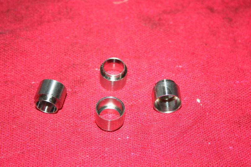 Oh yeah. They were machined from some 316 that I had lying around. 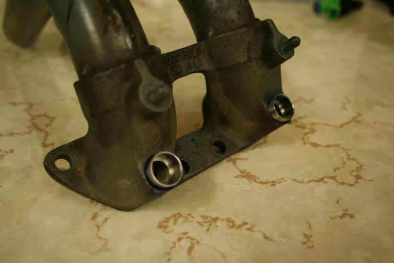 Sleeves pressed in. The press fit was perfect. Not too tight. Not too loose. 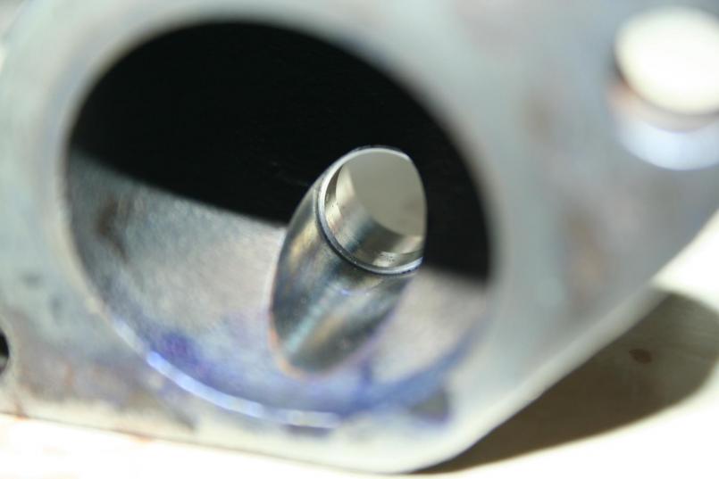 Port side. Mark D. |
|
|
|
| BMXerror |
Jan 26 2011, 11:39 PM
Post
#90
|
|
Senior Member Group: Members Posts: 1,705 Joined: 8-April 06 From: Hesperia Ca Member No.: 5,842 |
 Injectors installed. Feels good to start putting stuff together. 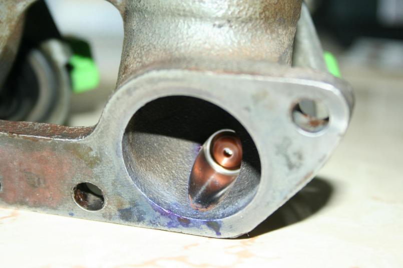 It took some careful calculation to get the depth of the injector approximately as the stock ones were. I think I did okay. That's it for tonight. There is more done that I still need to get pictures of. I'm hoping to be back on the road in a month or so. Then the fun part begins... Mapping! (IMG:style_emoticons/default/piratenanner.gif) Mark D. |
|
|
|
|
1 User(s) are reading this topic (1 Guests and 0 Anonymous Users)
0 Members:

|
Lo-Fi Version | Time is now: 12th May 2024 - 04:36 PM |
Invision Power Board
v9.1.4 © 2024 IPS, Inc.