|
|
|
Porsche, and the Porsche crest are registered trademarks of Dr. Ing. h.c. F. Porsche AG.
This site is not affiliated with Porsche in any way. Its only purpose is to provide an online forum for car enthusiasts. All other trademarks are property of their respective owners. |
|
|

  |

| Brando |
 Jan 7 2008, 03:52 PM Jan 7 2008, 03:52 PM
Post
#1
|
|
BUY MY SPARE KIDNEY!!!  Group: Members Posts: 3,935 Joined: 29-August 04 From: Santa Ana, CA Member No.: 2,648 Region Association: Southern California |
Hey there,
On my never-ending quest to make my L-jet more modern and reliable at a cost less than an aftermarket injection system, I'm needing the help of an electrical specialist. I plan to be switching over to a hall-effect sensor that reads pulses at both TDC and BDC of the flywheel. I have my magnetic poles to attach to the flywheel as well as the sensor (Speed/Ref sensor from a 944). The problem being the sensor normally has 1.2 ~ 1.5 Volts going through it for Motronic. I believe I can safely pass 12V ~13V max through the sensor without frying it. Problem being my injection system, receiving the trigger through this sensor, would have to see 16V ~ 18V. I would need a way to step up the voltage from 12V to 16V-18V. Since changing over to the hall-effect sensor will require some drilling and tapping of the case (not to mention balancing the flywheel), I plan to use the tach-output from my Mallory MSD box to trigger the tach and injection. Basically the box puts out a 12V square-wave which doesn't have enough voltage to trigger the tach or ECU. So I also need an electrical component that would take that 12V and turn it into a 16V-18V spike, as well as limit the voltage to 18V. I have not measured the amperage going through that circuit. I was thinking of running a small coil (same one I had to use for the points on the tach output to the ecu/tach but I don't know if that much voltage will cause it damage. So, I need some help. Can anyone assist? |
   |

 
|
| pin31 |
Jan 7 2008, 07:05 PM
Post
#2
|
|
Member Group: Members Posts: 398 Joined: 30-January 07 From: Newport, Rhode Island Member No.: 7,492 Region Association: North East States |
Understand where your going with this although I don't think there's enough info to provide a solid solution.
You can use a simple DC to DC converter to boost and regulate the signal (digi-key electronics on line catalog has a bunch) but I think this approach is an oversimplification. How can you assure your sensor is dead nuts TDC or BDC? How about adjustment? Signal characteristics etc... There are many factors to account for and the solution needs to incorporate an end to end systems approach (sensor, MSD, ECU parameters and characteristics). Ultimately, a microprocessor/controller based circuit (with appropriately matched sensors and I/O) functioning as a system, with adjustment control of key parameters is what I believe you would need. But isn't that really an after market injection system? I like your idea and it would be fun to experiment (think how much time and effort the after market guys have spent). Tim |
|
|
|
| Brando |
Jan 7 2008, 08:25 PM
Post
#3
|
|
BUY MY SPARE KIDNEY!!! Group: Members Posts: 3,935 Joined: 29-August 04 From: Santa Ana, CA Member No.: 2,648 Region Association: Southern California |
Tim,
I'm not so sure I get what you're saying. As for being assure my timing is dead nuts with the poles, I'm attaching them at TDC and BDC to be sure they're exact. This is basically what I need: 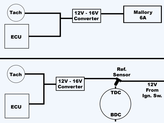 Kinda rustic and simple, I know. As I said I'm not sure what component I would need to step the voltage up to 16V. This is the best I could find that gives a breakdown on how the L-Jet ECU need the pulses from the trigger (input): http://bama.ua.edu/~darren/bosch/Page17.html better breakdown: http://demo.cs.brandeis.edu/postscript.dum...ronic/mods.html I hope that can give a better grasp of my intent with this. The Mallory box outputs a 12V Square-Wave. The whole system is DC. |
|
|
|
| banger |
Jan 7 2008, 09:03 PM
Post
#4
|
|
Member Group: Members Posts: 354 Joined: 12-November 06 From: Santa Clarita Member No.: 7,205 Region Association: Southern California |
You will need a dc-dc converter for the higher voltage, and a way of switching the output. Toshiba makes a chip that will do this, the part number is TD62784APG. Although its probably easier to use a tach adapter to do this. The main question is to why you want to use a hall sensor for TDC and BDC, since you cant drive ignition off of this, since there will be no timing advance. The easier way is to buy a Vanagon distributor, which has a hall sensor in it, and will provide you will pulses properly timed for all 4 cylinders.
|
|
|
|
| Spoke |
Jan 7 2008, 09:29 PM
Post
#5
|
|
Jerry Group: Members Posts: 6,978 Joined: 29-October 04 From: Allentown, PA Member No.: 3,031 Region Association: None |
What you want to do should be easy enough with off the shelf parts. With the limited info given, it looks like a step-up converter with a level shifter will do the job.
The step-up converter will provide 18V dc and a level shifter using a high speed comparator or the like will transform the input voltage to output voltage swing of 0 to 18V. Maxim or Linear Tech has many step-up converters to fit the bill. Most will require only a few components to proper set the voltage to what you want. The comparator could be set up to switch at 1/2 battery voltage so that below about 6V, the output would be low and above 6V the output would be high (18V). Here's a comparator which can be used to show feasibility of doing this conversion. Linear Tech Comparator This is the first one I found on the web. I would look for one which is a bit faster than this one. Spoke |
|
|
|
| Spoke |
Jan 7 2008, 09:36 PM
Post
#6
|
|
Jerry Group: Members Posts: 6,978 Joined: 29-October 04 From: Allentown, PA Member No.: 3,031 Region Association: None |
QUOTE(banger @ Jan 7 2008, 10:03 PM)  Toshiba makes a chip that will do this, the part number is TD62784APG. I just looked up the TD62784APG. It looks like a good fit for this application for the level shifter. Just need to add an appropriate pull-down resistor. |
|
|
|
| pin31 |
Jan 8 2008, 07:06 AM
Post
#7
|
|
Member Group: Members Posts: 398 Joined: 30-January 07 From: Newport, Rhode Island Member No.: 7,492 Region Association: North East States |
The bosch tech article is a good write up on the inner workings of the ECU.
I think there are a few fundamental issues with your approach (although I'd be the first to admit I know little about the L-jetronics/ECU injection electrical details). 1. mechanically mounting the sensors with the accuracy needed (without being able for adjustment mechanically or electrically) will be a challenge. 2. If your triggering on TDC and BDC you may be too late to pulse the ECU which may mess with the voltage correction timing pulse or overall multiplying stage timing. 3. Probably most significant, and related to #2, the ignition trigger pulse wave form. The wave form you'll produce will be more like a slewed or rounded off square wave and not the well defined spike on the leading edge of the pulse (as shown in the Bosch tech article). The spike on the leading edge is the reference point for the overall injection timing and more important the triggering pulses for the injection valves. I still think it would be fun to experiment (although I would create a bench test setup) and use an o-scope to view the pulse timing and shape. Tim |
|
|
|
| Brando |
Jan 8 2008, 03:54 PM
Post
#8
|
|
BUY MY SPARE KIDNEY!!! Group: Members Posts: 3,935 Joined: 29-August 04 From: Santa Ana, CA Member No.: 2,648 Region Association: Southern California |
Let me specify... this is just for triggering the Tach/ECU injection. This in no way will control the timing of the ignition.
I have found that the best (ideal) position for the sensor pickups is 8.5º-10º before TDC (idle ignition advance setting), easy to find with a protractor and original TDC/BDC marks. The tach it doesn't matter where, as long as the poles are 180º apart. Thank you for the input guys. I'll look into a DC-DC converter. My original idea was for the tach output to trigger a solid-state relay that would then switch voltage from a small coil (spike in voltage) to the tach/ECU. Solid State Relays in the 12V flavor aren't as common as I thought. |
|
|
|
|
1 User(s) are reading this topic (1 Guests and 0 Anonymous Users)
0 Members:

|
Lo-Fi Version | Time is now: 17th May 2024 - 06:50 PM |
Invision Power Board
v9.1.4 © 2024 IPS, Inc.