|
|
|
Porsche, and the Porsche crest are registered trademarks of Dr. Ing. h.c. F. Porsche AG.
This site is not affiliated with Porsche in any way. Its only purpose is to provide an online forum for car enthusiasts. All other trademarks are property of their respective owners. |
|
|

  |

| Spoke |
 Apr 6 2008, 11:25 PM Apr 6 2008, 11:25 PM
Post
#1
|
|
Jerry  Group: Members Posts: 6,978 Joined: 29-October 04 From: Allentown, PA Member No.: 3,031 Region Association: None |
I'm prepping a 1.8L engine for the red 914 to replace the leaky 1.7L with one cylinder low on compression that's in the car. The installed engine has dual IDF40 Webers on it now.
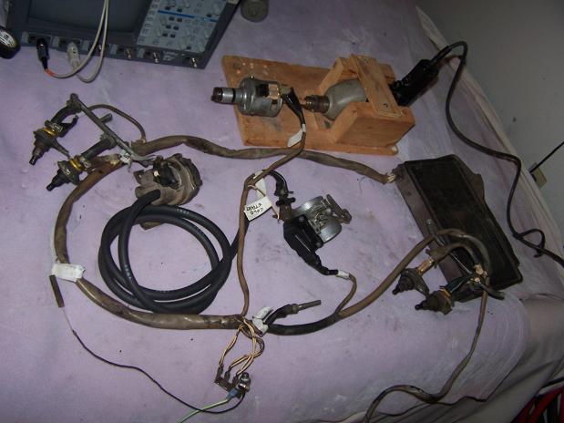
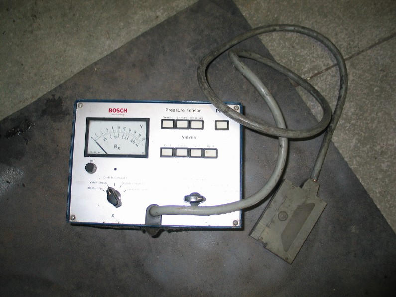
When the PO bought the car, it had FI and was not running or was not running good. He took it to a local 356 shop and they pulled the FI and put on a single Weber just to get the car running. When the 356 shop moved locations, I received a box full of FI stuff from the car. My goal is to test each component and get the FI running again. I've tested most of the components including the distributor contact points, temp senders, throttle switch, and MPS. For the MPS, I just tested for vacuum leakage. It was leaking pretty badly so I took it apart and sealed it. I'll test it when I test the FI brain. I got a few questions that I'll get to in a few posts. First question is will it damage injectors if they are operated w/o fuel pressure? I plan to run the brain with injectors dry. Here's all the stuff I received: Attached image(s) 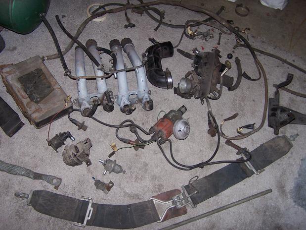
|
   |

 
|
| Spoke |
Apr 6 2008, 11:39 PM
Post
#2
|
|
Jerry Group: Members Posts: 6,978 Joined: 29-October 04 From: Allentown, PA Member No.: 3,031 Region Association: None |
To test the brain, I made a temporary harness to go from a battery to the FI. The harness has a fuse, on/off switch (imitates ignition switch) and pushbutton switch (imitates starter).
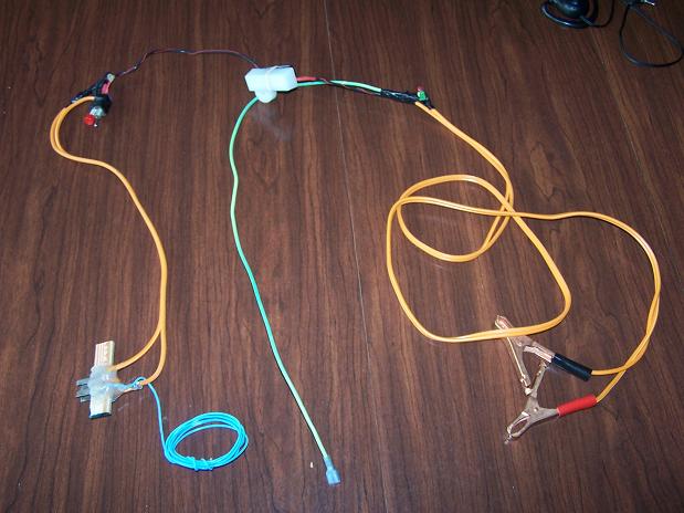 To power the brain, I made a connector like the one on the relay board. To make the connector, I started with small strips of 20 or 22ga steel such that each one would fit into the pins of the 4 pin connector to the brain. After soldering wires onto the lugs, I put the lugs in the 4 pin connector, then placed a piece of wood between the rows of pins, then hot-melt glued the spades to the wood. This made a very secure connector for the 4 pin brain power connector. The blue wire will power the fuel pump relay once I put the FI on the engine and attempt to fire it up. 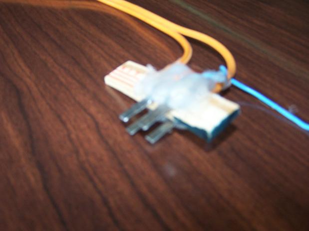 Toggle is on/off control and the red pushbutton is for the starter. 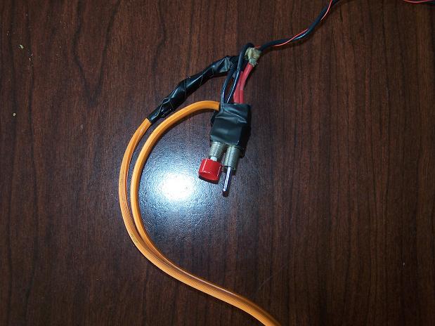 I put red and green LEDs on the harness for status. The red LED lights if the battery is connected backwards. The green LED lights when the on/off switch is on. The fuse is just in case something gets shorted. 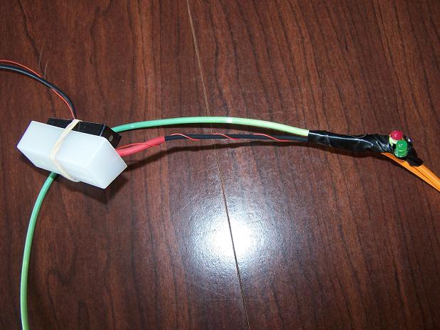 |
|
|
|
| Spoke |
Apr 7 2008, 12:00 AM
Post
#3
|
|
Jerry Group: Members Posts: 6,978 Joined: 29-October 04 From: Allentown, PA Member No.: 3,031 Region Association: None |
Here's the brain with all its components connected. I want to run the brain with the distributor spinning with a drill. This is just to make sure the distributor works.
 This is the "engine block". It was made from a small piece of 22ga steel. I put a series of cuts in one side and bent up every other tab to form several spades for electrical connectors. On the right is the CHT sending unit. 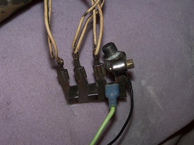 Here's the power connector for the brain. 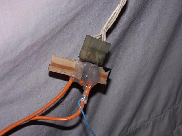 To test injectors and distributor functions, I made some extenders out of 0.016in brass. Again with a piece of wood and hot-melt glue, connectors were made. These allow easy measuring of signals. The one with 3 leads is for the distributor. 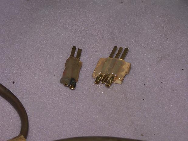 Here's a shot of the drill driving the distributor. This worked but the drill lacked the ability to remain at a certain speed and the drill caused annoying spiking on the scope. The drill + distributor has been replaced by an electronic circuit. 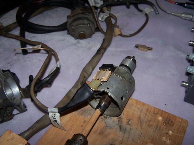 Here's injector #1 with an extender for measuring injector voltage. 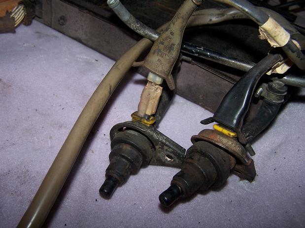 The CHT sender did not have a connector so I made one from brass and soldered the CHT sender to it. 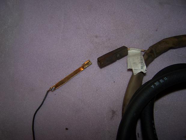 |
|
|
|
| Spoke |
Apr 7 2008, 12:19 AM
Post
#4
|
|
Jerry Group: Members Posts: 6,978 Joined: 29-October 04 From: Allentown, PA Member No.: 3,031 Region Association: None |
The drill+distributor worked well to show that the distributor contacts were ok but the drill is hard to set at a certain speed and also makes a lot of noise.
There are 2 contact points 180 degrees out of phase with each other and open and close once every single rotation of the distributor (2 rotations of the crankshaft) To simulate the 2 contact points of the spinning distributor, I use 2 FETs, one for each contact. To provide the speed, I use a 555 timer with potentiometer to vary the engine speed. The 555 is followed by a CD4040 ripple counter. The ripple counter slows down the frequency from the 555 (it was too fast) and also squares up the output. By choosing different outputs of the ripple counter, I am able to get the engine speed to vary from about 100RPM to over 5000RPM. The ripple counter is followed by a CD4049 hex inverter. One FET is driven by a single inverter and the other by 2 inverters to provide out of phase signals. 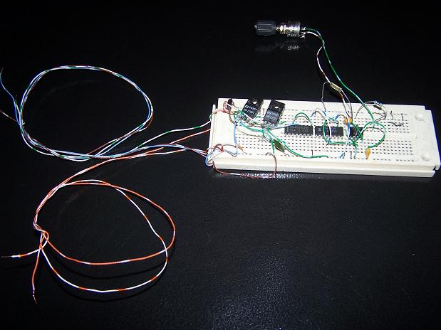 To simulate the CHT sender, I used a potentiometer to vary the resistance from 3500 ohms (engine cold) to 1000 ohm (engine hot). The resistor with lead pointing up is 1000 ohms so when pot set to 0 ohms, the CHT sender is 1000 ohms. The other 3 resistors in parallel with the pot lower the 5K ohm equivalent resistance to 2.5K ohms. 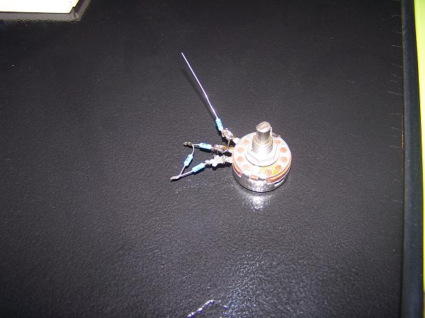 |
|
|
|
| Spoke |
Apr 7 2008, 12:35 AM
Post
#5
|
|
Jerry Group: Members Posts: 6,978 Joined: 29-October 04 From: Allentown, PA Member No.: 3,031 Region Association: None |
Below are some scope traces of distributor contacts (trace 1, top trace) and #1 injector voltage (trace 2, bottom trace). The top trace shows a period of 150ms. This equates to 1/0.150 x 2 x 60 = 800 RPM. Each trace is 5V/div vertical and 20ms/div horizontal.
For the following trace, the MPS has no vacuum and the CHT sender is open circuited. Note the very long injector pulses (trace 2). Question: Note the injector voltage (trace 2). The injector voltage spikes up to 12 volts then settles to about 5V. Is this normal? I would have expected the entire spike to be 12V. The injectors seem to be operating even with the low voltage. 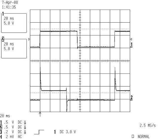 Same speed, 800 RPM with the CHT sender connected and cold (3500 ohms; room temp). No vacuum on the MPS. Note the injector pulse is shorter. 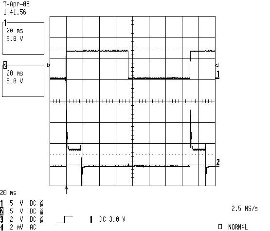 Same speed, 800 RPM with the CHT sender connected and hot (1000 ohms). No vacuum on the MPS. Injector pulse even shorter. Warmed up engine condition. 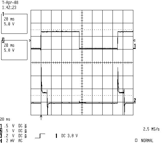 Same speed, 800 RPM with CHT sender connected and hot, and MPS in vacuum. This is the normal warm engine idling condition with MPS in vacuum. 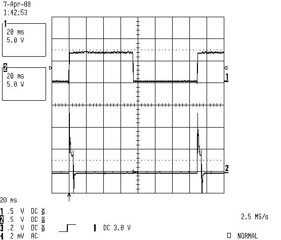 |
|
|
|
| swl |
Apr 7 2008, 06:27 AM
Post
#6
|
|
Senior Member Group: Members Posts: 1,409 Joined: 7-August 05 From: Kingston,On,Canada Member No.: 4,550 Region Association: Canada |
|
|
|
|
| root |
Apr 7 2008, 07:38 AM
Post
#7
|
|
Two Wheeled Type4 Completed! Group: Members Posts: 849 Joined: 5-May 04 From: Sterling, VA Member No.: 2,026 Region Association: None |
Spoke,
I haven't scoped the injector voltage myself but if you look at 'banders' site he got a very similar result to yours and it makes sense 'cause the injector coil is inductive causing it to appear as a high impedance upon the initial step pulse from the ECU driver transistor. In milliseconds the injector coil impedance drops down low hence the corresponding voltage drops. http://members.rennlist.com/pbanders/ecu.htm#D1-D2 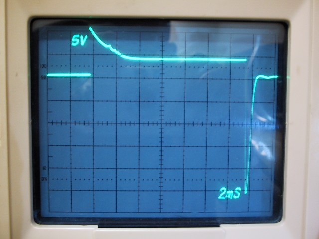 I like what your methodology dude! A "Real seat of the pants" effort, which appears to be working! Let's see what happens when you pull a vacuum on the MPS now! (IMG:style_emoticons/default/aktion035.gif) |
|
|
|
| Bleyseng |
Apr 7 2008, 09:23 AM
Post
#8
|
|
Aircooled Baby! Group: Members Posts: 13,034 Joined: 27-December 02 From: Seattle, Washington (for now) Member No.: 24 Region Association: Pacific Northwest |
looks like its working but I would junk the injectors and buy new ones from BusDepot.com under the 411 section. Cheap and makes a huge difference....
you can also just have them cleaned by Witchhunter.com How did you seal the MPS? |
|
|
|
| freezing14 |
Apr 7 2008, 06:31 PM
Post
#9
|
|
freezing14 Group: Members Posts: 435 Joined: 21-June 04 From: brockville , Ontario, Canada Member No.: 2,233 |
thats a really great set up you have there , but I like that one too
 |
|
|
|
| Spoke |
Apr 8 2008, 03:21 PM
Post
#10
|
|
Jerry Group: Members Posts: 6,978 Joined: 29-October 04 From: Allentown, PA Member No.: 3,031 Region Association: None |
Root,
Thanks for the info and link. Excellent reading material. Just what I was looking for. I feel better about the 5V injector voltages. I've removed the injectors and replaced with 3 ohm power resistors. Now the injector waveforms look a lot better. Bleyseng, I sealed the MPS by taking the seal out, cleaning it off, then sealing with some red gasket spray. Put back together and no leak. If it doesn't last, I'll be looking for another one. At least it gets me going. |
|
|
|
| Spoke |
Apr 8 2008, 03:27 PM
Post
#11
|
|
Jerry Group: Members Posts: 6,978 Joined: 29-October 04 From: Allentown, PA Member No.: 3,031 Region Association: None |
Now to test the throttle contacts.
I did the open slowly and listen for 20 burps from the injectors. This looks ok. Now to test the throttle-closed switch. Set the engine speed to 2000 rpm, engine warm, MPS under vacuum. Following shot is with the throttle open. Normal injector pulse as expected. Note the nice square injector wave now that the injector is replaced by a resistor. 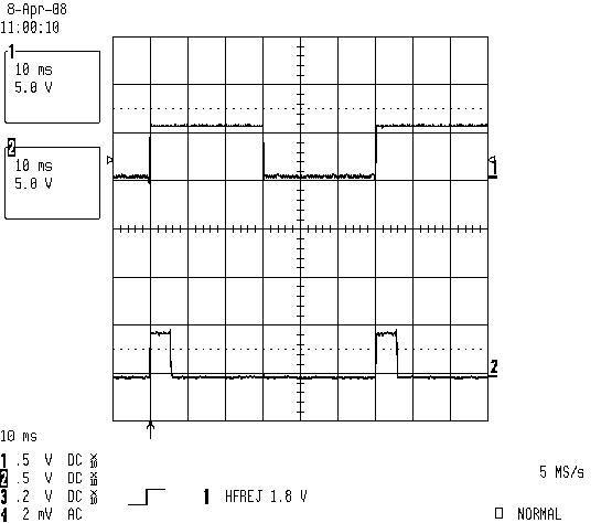 Close the throttle at 2000 rpm and the injector pulse decreases to a spike as expected. When injectors are connected during this test, there are no audible sounds from the injectors thus they are not opening at all with this little spike. 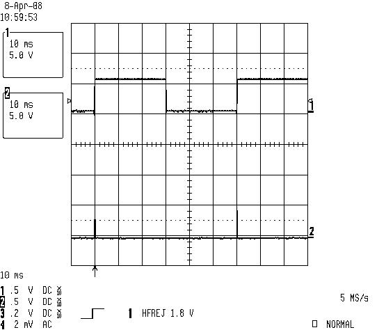 |
|
|
|
| Spoke |
Apr 8 2008, 03:32 PM
Post
#12
|
|
Jerry Group: Members Posts: 6,978 Joined: 29-October 04 From: Allentown, PA Member No.: 3,031 Region Association: None |
Still checking decel operation. With throttle closed, checking the engine speed at which the pulses re-appear. In the waveform below, the injectors come back on at around 1100 rpm.
Attached image(s) 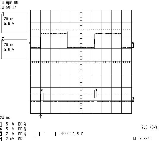
|
|
|
|
| Spoke |
Apr 8 2008, 03:44 PM
Post
#13
|
|
Jerry Group: Members Posts: 6,978 Joined: 29-October 04 From: Allentown, PA Member No.: 3,031 Region Association: None |
OK, now I don't know how to interpret this. My understanding is when the engine speed is above 1100rpm or so, when the throttle is closed, the injectors should cut off. This is not what I see.
Below is a shot of the engine at 6000 rpm, MPS under vacuum, CHT warm. The injector ON width doesn't change regardless of throttle open or closed. I thought when throttle closed, I would see the little injector spikes, not normal wide pulses. WTF? 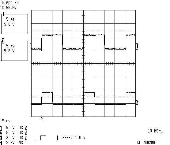 So with the throttle closed, I reduced the engine speed down until the injectors turned off as shown below. This occurred at about 2850 RPM. The injector pulses will remain spikes until the engine speed goes below 1100 rpm when normal injector pulses reappear. So is this normal behaviour for the engine to cut off the injector pulses between about 1100 and 2850 rpm. Above 2850 I get normal width injector pulses regardless of the throttle position. 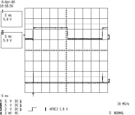 |
|
|
|
| r_towle |
Apr 8 2008, 09:38 PM
Post
#14
|
|
Custom Member Group: Members Posts: 24,574 Joined: 9-January 03 From: Taxachusetts Member No.: 124 Region Association: North East States |
two things.
Your TPS is out of adjustment, or its worn at that point. They do wear out and they wear out at cruising...so 2850 is probably worn... Open it up, clean it with a tooth brush and elec cleaner. Mine does this also.. I wonder if its switching from one contact to the next at that point in time...there are three or four contacts in there. Rich |
|
|
|
|
1 User(s) are reading this topic (1 Guests and 0 Anonymous Users)
0 Members:

|
Lo-Fi Version | Time is now: 14th May 2024 - 10:33 PM |
Invision Power Board
v9.1.4 © 2024 IPS, Inc.