|
|
|
Porsche, and the Porsche crest are registered trademarks of Dr. Ing. h.c. F. Porsche AG.
This site is not affiliated with Porsche in any way. Its only purpose is to provide an online forum for car enthusiasts. All other trademarks are property of their respective owners. |
|
|


| strawman |
 Apr 18 2008, 12:19 AM Apr 18 2008, 12:19 AM
Post
#101
|
|
Senior Member  Group: Members Posts: 891 Joined: 25-January 08 From: Los Osos, CA Member No.: 8,624 Region Association: Central California |
Hi All --
This is my second post, but I've been lurking on this fine website for a while now. I've wanted a 914 since I was in high school, but always seemed to stumble upon other projects... until recently. My neighbor gave me this 1973 Porsche 914 about a month ago. He told me he blew a head gasket and parked it in his parents' driveway in 1992. When his parents finally told him to move it or they were calling a local junkyard, he offered it to me since he knows I'm a gearhead. In for a penny, in for a pound... I hauled it home, knowing that it has some rust issues in the battery area and rear trunk. But it appears to have never been in a wreck and it is complete. It turns out that an exhaust stud pulled, so he coulda fixed it for a couple hundred and probably kept another 914 from languishing but I guess all things happen for a reason (namely, so I would undertake this project!). I sold the engine to a local Craigslister for use in his Meyers Manx dune buggy, and bought a wrecked but running 1993 Subaru Legacy turbo wagon. This is the closed-deck 2.2 liter engine, and 250 hp is easy with boost control and an open exhaust. I've already done a Subaru into a VW Vanagon and my daily driver is a 1992 Suby Legacy, so this won't be too much of a stretch for me. I plan to use the Suby 5-speed transmission (out of a 1998 Suby Forester) with the Aussie-sourced RWD elimination coupler and custom-mated 914/Suby axles. I've got a suburban home with a crowded two-car garage (my 125 shifter kart and my daughter's FJA kart will likely get lonely!), a MIG welder, and a wide assortment of air/power/hand tools -- so the adventure begins! This project will likely take a year to finish, so please be patient. I've attached some pics of the car as found in the driveway, some rust areas and the rear trunk repairs I've started. I'll chronicle the build as I go, so feel free to chime in! Geoff Attached image(s) 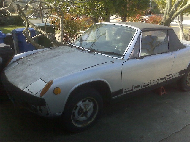 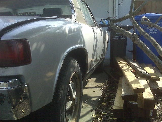 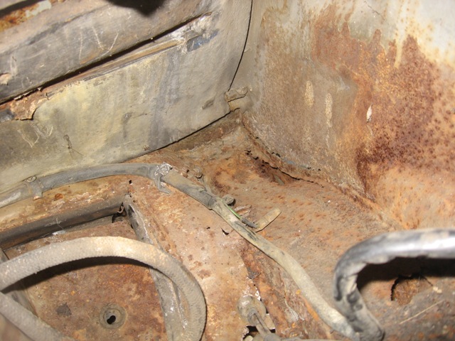
|
   |

 
|
Posts in this topic
strawman Suby-engined rustoration Apr 18 2008, 12:19 AM strawman More pics of the rust in/around the battery tray a... Apr 18 2008, 12:25 AM strawman Here are some pics of the front and rear trunks...... Apr 18 2008, 12:30 AM strawman Here are some pics of windshield/cowl area that... Apr 18 2008, 12:33 AM strawman Okay, here are some pics of the rear trunk area. I... Apr 18 2008, 12:41 AM strawman More trunk pics... Apr 18 2008, 12:45 AM strawman More... Apr 18 2008, 12:46 AM strawman And some more, with the AA trunk pan mocked up... Apr 18 2008, 12:49 AM strawman Finally, here are some pics of the gaps near the f... Apr 18 2008, 12:50 AM strawman I've ordered some POR-15 supplies and some Wur... Apr 18 2008, 12:56 AM charliew Hi Strawman, Good work sofar, I hope you don't... Apr 18 2008, 10:16 AM
 strawman
Mind explaining the 99 forester tranny choice?
... Apr 18 2008, 11:17 AM Zaney Awesome start! I am going to dive into my Sub... Apr 18 2008, 11:00 AM strawman Been a while since I last posted, but I've bee... Jul 9 2008, 12:04 PM strawman Here is a pic of the rear trunk/panel, ready for i... Jul 9 2008, 12:16 PM strawman Here are two closeup pics of the rear corners, tha... Jul 9 2008, 12:19 PM strawman Now for a pic of the rotisserie parts. I bought a ... Jul 9 2008, 12:45 PM tdgray Good work... keep it up... I've done worse and... Jul 9 2008, 03:37 PM strawman Look what showed up today at my doorstep... the Br... Jul 17 2008, 09:02 PM rick 918-S :wttc: :headbanger: :popcorn: Jul 17 2008, 10:22 PM strawman Got the car up on the rotisserie today. Used my ch... Jul 19 2008, 07:51 PM strawman It has been a while since I last posted, but I hav... Aug 16 2008, 09:40 PM strawman Next up is a pic of the patch piece, made of 16 ga... Aug 16 2008, 09:59 PM strawman Here is a pic of lower patch piece, made of 18 ga.... Aug 16 2008, 10:25 PM Hammy Awesome progress.
How are you planning on mounti... Aug 17 2008, 04:06 AM strawman
How are you planning on mounting your Suby engine... Aug 21 2008, 11:33 PM plymouth37 Very cool! Looking forward to following your p... Aug 21 2008, 11:44 PM roadster fan Nice work, makes me wanna go fire up the mig and t... Aug 22 2008, 06:54 AM strawman It has been a while since I last posted and work h... Sep 26 2008, 11:35 AM strawman Here is another pic of the jig...
Here is a pic... Sep 26 2008, 11:44 AM pktzygt OK, this and a few other treads are my motivation ... Oct 2 2008, 02:06 PM FourBlades Nice work! :Qarl: Take more pictures, you ... Oct 2 2008, 07:47 PM rick 918-S :popcorn: Oct 3 2008, 06:11 PM tronporsche You will no doubt be able to be one of the guys th... Oct 3 2008, 06:51 PM strawman Been a while since my last post, but I've made... Nov 16 2008, 11:16 PM strawman Next up are some other pics of the passenger side ... Nov 16 2008, 11:21 PM strawman I sandblasted the entire inner long to get down to... Nov 16 2008, 11:34 PM strawman Next up is a pic of the jack post, followed by the... Nov 16 2008, 11:53 PM FourBlades Beautiful work dude! :Qarl:
Keep it going... Nov 17 2008, 08:33 AM Zaney Awesome work!
Make sure that breathing apparat... Nov 17 2008, 11:23 AM strawman Had all of last week off work, but we had family i... Dec 2 2008, 11:32 PM strawman On Sunday, I finished up welding in the rear trunk... Dec 3 2008, 12:13 AM FourBlades Looking good. :Qarl:
You made some great progr... Dec 3 2008, 08:10 AM Root_Werks Wow! Great work, I can't believe I didn... Dec 3 2008, 09:32 AM my928s4 Nice fabrication work, you have given me some idea... Dec 3 2008, 11:44 AM strawman Been a while since I posted, and work/family has g... Jan 10 2009, 10:38 PM strawman Here's some pics of the driver's side. As ... Jan 10 2009, 10:47 PM strawman Finally, here's some of the trailing arm stiff... Jan 10 2009, 11:02 PM jc914 Nice work :popcorn: Jan 11 2009, 12:13 PM strawman The AA rocker covers that I bought as part of the ... Jan 21 2009, 11:31 PM charliew My wife seems afraid of my shop which is ok to me.... Jan 22 2009, 01:12 PM Zaney Geoff,
Could you post a picture of the "burr ... Jan 22 2009, 03:22 PM charliew A burr is a term for a carbide bit that fits in a ... Jan 24 2009, 01:19 PM strawman
A burr is a term for a carbide bit that fits in a... Jan 25 2009, 10:26 PM strawman I bought a 1969 911 rear suspension/brake system t... Jan 25 2009, 10:54 PM strawman I picked up a 1976 911 roller for parts a couple o... Feb 18 2009, 11:04 AM dlo914 Great work so far! Will definitely follow your... Feb 18 2009, 12:46 PM strawman My hip replacement surgery went well, and I've... Apr 26 2009, 09:41 PM strawman I knew there was a mess under the passenger side s... Apr 26 2009, 10:30 PM strawman The forward/lower area of the passenger side quart... Apr 26 2009, 10:48 PM Zaney Good to see you up and moving around, Geoff! ... Apr 27 2009, 09:27 AM strawman Been a while since I last posted, but I've bee... May 25 2009, 10:01 PM strawman I also decided to modify the coolant crossover pip... May 25 2009, 10:37 PM strawman Still been plugging away...
Below are some pics o... Jun 3 2009, 11:36 PM strawman Tonite I also welded on the lower passenger side q... Jun 3 2009, 11:55 PM Gint Awesome work!
First up is a pic of the jack po... Jun 4 2009, 07:34 AM strawman
Awesome work!
First up is a pic of the jack p... Jun 4 2009, 06:42 PM al weidman Geoff, I have tried to find the "easy-grind... Jun 5 2009, 12:34 AM strawman
Geoff, I have tried to find the "easy-grind... Jun 5 2009, 12:42 PM charliew I have never came across a brazed tube in a alumin... Jun 5 2009, 02:13 PM strawman
I have never came across a brazed tube in a alumi... Jun 5 2009, 06:09 PM charliew You can put your hand on my sons sti after driving... Jun 6 2009, 04:27 PM strawman
You can put your hand on my sons sti after drivin... Jun 7 2009, 08:49 PM strawman Had a chance to spend some more quality time with ... Jun 7 2009, 08:55 PM biosurfer1 Get anything good at the swap meet? Jun 7 2009, 08:59 PM strawman
Get anything good at the swap meet?
As stated a... Jun 7 2009, 09:13 PM strawman Both lower corners of my windshield are crusty. I ... Jun 7 2009, 09:10 PM biosurfer1 I couldn't make it but Justin (didn't he g... Jun 7 2009, 09:31 PM charliew Strawman I don't know how much studying you... Jun 8 2009, 09:11 AM strawman Over the past few weeks, I've been cleaning up... Jul 20 2009, 11:44 PM strawman Next up is the engine cradle, built out of 1... Jul 21 2009, 12:17 AM strawman I haven't posted in a while, but I've been... Aug 24 2009, 01:43 PM strawman Here are some pics of the suspension stuff I picke... Sep 3 2009, 10:56 PM strawman A little update...
I welded on the front sway bar... Sep 12 2009, 10:44 PM strawman Okay, so I just got another cocktail, and thought ... Sep 12 2009, 11:08 PM strawman And here are a couple of pics of the main and mid ... Sep 12 2009, 11:12 PM charliew I like the engine cradle it's similiar to Tony... Sep 17 2009, 11:14 PM strawman
<snip>
... Since you are not changing the r... Sep 18 2009, 07:33 PM strawman
Are you going to expect the pinion depth to remai... Sep 21 2009, 02:16 PM charliew I'm sorry Geoff, by early I meant the 99 and e... Sep 22 2009, 07:54 AM strawman So I finished up the installation of the OBX limit... Sep 23 2009, 11:12 PM strawman Now that the transmission is ready to go, I starte... Sep 23 2009, 11:32 PM strawman I finally got around to finishing the rear trunk r... Oct 22 2009, 01:12 AM JazonJJordan Awesome work and rustoration! Thanks for docum... Oct 22 2009, 10:20 AM Justinp71 Looking good! Oct 22 2009, 10:30 AM charliew Geoff great pictures, I guess you decided 1.5 notc... Oct 22 2009, 11:48 AM strawman
... I didn't get how you measured side to sid... Oct 22 2009, 12:04 PM strawman Finally took some pics of my modified trailing arm... Oct 24 2009, 12:35 AM DBCooper Extremely well done. You're knocking out thin... Oct 24 2009, 05:49 AM al weidman Geoff, just reviewed the thread so I can remember ... Oct 30 2009, 11:55 PM
strawman
Mind explaining the 99 forester tranny choice?
... Apr 18 2008, 11:17 AM Zaney Awesome start! I am going to dive into my Sub... Apr 18 2008, 11:00 AM strawman Been a while since I last posted, but I've bee... Jul 9 2008, 12:04 PM strawman Here is a pic of the rear trunk/panel, ready for i... Jul 9 2008, 12:16 PM strawman Here are two closeup pics of the rear corners, tha... Jul 9 2008, 12:19 PM strawman Now for a pic of the rotisserie parts. I bought a ... Jul 9 2008, 12:45 PM tdgray Good work... keep it up... I've done worse and... Jul 9 2008, 03:37 PM strawman Look what showed up today at my doorstep... the Br... Jul 17 2008, 09:02 PM rick 918-S :wttc: :headbanger: :popcorn: Jul 17 2008, 10:22 PM strawman Got the car up on the rotisserie today. Used my ch... Jul 19 2008, 07:51 PM strawman It has been a while since I last posted, but I hav... Aug 16 2008, 09:40 PM strawman Next up is a pic of the patch piece, made of 16 ga... Aug 16 2008, 09:59 PM strawman Here is a pic of lower patch piece, made of 18 ga.... Aug 16 2008, 10:25 PM Hammy Awesome progress.
How are you planning on mounti... Aug 17 2008, 04:06 AM strawman
How are you planning on mounting your Suby engine... Aug 21 2008, 11:33 PM plymouth37 Very cool! Looking forward to following your p... Aug 21 2008, 11:44 PM roadster fan Nice work, makes me wanna go fire up the mig and t... Aug 22 2008, 06:54 AM strawman It has been a while since I last posted and work h... Sep 26 2008, 11:35 AM strawman Here is another pic of the jig...
Here is a pic... Sep 26 2008, 11:44 AM pktzygt OK, this and a few other treads are my motivation ... Oct 2 2008, 02:06 PM FourBlades Nice work! :Qarl: Take more pictures, you ... Oct 2 2008, 07:47 PM rick 918-S :popcorn: Oct 3 2008, 06:11 PM tronporsche You will no doubt be able to be one of the guys th... Oct 3 2008, 06:51 PM strawman Been a while since my last post, but I've made... Nov 16 2008, 11:16 PM strawman Next up are some other pics of the passenger side ... Nov 16 2008, 11:21 PM strawman I sandblasted the entire inner long to get down to... Nov 16 2008, 11:34 PM strawman Next up is a pic of the jack post, followed by the... Nov 16 2008, 11:53 PM FourBlades Beautiful work dude! :Qarl:
Keep it going... Nov 17 2008, 08:33 AM Zaney Awesome work!
Make sure that breathing apparat... Nov 17 2008, 11:23 AM strawman Had all of last week off work, but we had family i... Dec 2 2008, 11:32 PM strawman On Sunday, I finished up welding in the rear trunk... Dec 3 2008, 12:13 AM FourBlades Looking good. :Qarl:
You made some great progr... Dec 3 2008, 08:10 AM Root_Werks Wow! Great work, I can't believe I didn... Dec 3 2008, 09:32 AM my928s4 Nice fabrication work, you have given me some idea... Dec 3 2008, 11:44 AM strawman Been a while since I posted, and work/family has g... Jan 10 2009, 10:38 PM strawman Here's some pics of the driver's side. As ... Jan 10 2009, 10:47 PM strawman Finally, here's some of the trailing arm stiff... Jan 10 2009, 11:02 PM jc914 Nice work :popcorn: Jan 11 2009, 12:13 PM strawman The AA rocker covers that I bought as part of the ... Jan 21 2009, 11:31 PM charliew My wife seems afraid of my shop which is ok to me.... Jan 22 2009, 01:12 PM Zaney Geoff,
Could you post a picture of the "burr ... Jan 22 2009, 03:22 PM charliew A burr is a term for a carbide bit that fits in a ... Jan 24 2009, 01:19 PM strawman
A burr is a term for a carbide bit that fits in a... Jan 25 2009, 10:26 PM strawman I bought a 1969 911 rear suspension/brake system t... Jan 25 2009, 10:54 PM strawman I picked up a 1976 911 roller for parts a couple o... Feb 18 2009, 11:04 AM dlo914 Great work so far! Will definitely follow your... Feb 18 2009, 12:46 PM strawman My hip replacement surgery went well, and I've... Apr 26 2009, 09:41 PM strawman I knew there was a mess under the passenger side s... Apr 26 2009, 10:30 PM strawman The forward/lower area of the passenger side quart... Apr 26 2009, 10:48 PM Zaney Good to see you up and moving around, Geoff! ... Apr 27 2009, 09:27 AM strawman Been a while since I last posted, but I've bee... May 25 2009, 10:01 PM strawman I also decided to modify the coolant crossover pip... May 25 2009, 10:37 PM strawman Still been plugging away...
Below are some pics o... Jun 3 2009, 11:36 PM strawman Tonite I also welded on the lower passenger side q... Jun 3 2009, 11:55 PM Gint Awesome work!
First up is a pic of the jack po... Jun 4 2009, 07:34 AM strawman
Awesome work!
First up is a pic of the jack p... Jun 4 2009, 06:42 PM al weidman Geoff, I have tried to find the "easy-grind... Jun 5 2009, 12:34 AM strawman
Geoff, I have tried to find the "easy-grind... Jun 5 2009, 12:42 PM charliew I have never came across a brazed tube in a alumin... Jun 5 2009, 02:13 PM strawman
I have never came across a brazed tube in a alumi... Jun 5 2009, 06:09 PM charliew You can put your hand on my sons sti after driving... Jun 6 2009, 04:27 PM strawman
You can put your hand on my sons sti after drivin... Jun 7 2009, 08:49 PM strawman Had a chance to spend some more quality time with ... Jun 7 2009, 08:55 PM biosurfer1 Get anything good at the swap meet? Jun 7 2009, 08:59 PM strawman
Get anything good at the swap meet?
As stated a... Jun 7 2009, 09:13 PM strawman Both lower corners of my windshield are crusty. I ... Jun 7 2009, 09:10 PM biosurfer1 I couldn't make it but Justin (didn't he g... Jun 7 2009, 09:31 PM charliew Strawman I don't know how much studying you... Jun 8 2009, 09:11 AM strawman Over the past few weeks, I've been cleaning up... Jul 20 2009, 11:44 PM strawman Next up is the engine cradle, built out of 1... Jul 21 2009, 12:17 AM strawman I haven't posted in a while, but I've been... Aug 24 2009, 01:43 PM strawman Here are some pics of the suspension stuff I picke... Sep 3 2009, 10:56 PM strawman A little update...
I welded on the front sway bar... Sep 12 2009, 10:44 PM strawman Okay, so I just got another cocktail, and thought ... Sep 12 2009, 11:08 PM strawman And here are a couple of pics of the main and mid ... Sep 12 2009, 11:12 PM charliew I like the engine cradle it's similiar to Tony... Sep 17 2009, 11:14 PM strawman
<snip>
... Since you are not changing the r... Sep 18 2009, 07:33 PM strawman
Are you going to expect the pinion depth to remai... Sep 21 2009, 02:16 PM charliew I'm sorry Geoff, by early I meant the 99 and e... Sep 22 2009, 07:54 AM strawman So I finished up the installation of the OBX limit... Sep 23 2009, 11:12 PM strawman Now that the transmission is ready to go, I starte... Sep 23 2009, 11:32 PM strawman I finally got around to finishing the rear trunk r... Oct 22 2009, 01:12 AM JazonJJordan Awesome work and rustoration! Thanks for docum... Oct 22 2009, 10:20 AM Justinp71 Looking good! Oct 22 2009, 10:30 AM charliew Geoff great pictures, I guess you decided 1.5 notc... Oct 22 2009, 11:48 AM strawman
... I didn't get how you measured side to sid... Oct 22 2009, 12:04 PM strawman Finally took some pics of my modified trailing arm... Oct 24 2009, 12:35 AM DBCooper Extremely well done. You're knocking out thin... Oct 24 2009, 05:49 AM al weidman Geoff, just reviewed the thread so I can remember ... Oct 30 2009, 11:55 PM  |
1 User(s) are reading this topic (1 Guests and 0 Anonymous Users)
0 Members:

|
Lo-Fi Version | Time is now: 2nd April 2026 - 01:48 PM |
Invision Power Board
v9.1.4 © 2026 IPS, Inc.