|
|
|
Porsche, and the Porsche crest are registered trademarks of Dr. Ing. h.c. F. Porsche AG.
This site is not affiliated with Porsche in any way. Its only purpose is to provide an online forum for car enthusiasts. All other trademarks are property of their respective owners. |
|
|

  |

| Mike Bellis |
 Jun 23 2011, 10:35 PM Jun 23 2011, 10:35 PM
Post
#201
|
|
Resident Electrician  Group: Members Posts: 8,348 Joined: 22-June 09 From: Midlothian TX Member No.: 10,496 Region Association: None |
QUOTE(pktzygt @ Jun 23 2011, 06:13 PM)  I know, I know I was just trying to convince myself a pusher fan might do the job for something like an intercooler. Pusher fans are never, ever as good as a puller through a radiator. It's like trying to push a rope. doesn't work. I'm putting my heat exchanger in the rear quarter panel. I'm ducting with either a Boxster side vent or a NACA duct. I also have to fab an inner fender skirt to keep rocks and mud from clogging the radiator. I need to go |
   |

 
|
| Heater Guy |
Jun 24 2011, 02:44 PM
Post
#202
|
|
Member Group: Members Posts: 74 Joined: 20-October 09 From: Walnut Creek, CA Member No.: 10,960 Region Association: Northern California |
I have a subaru 914 SCCA track car and planning to replace the 901 transaxle with the Subaru trans axle.
If you have a few minutes to give me some info. I would surely appreciate it. Ron Randolph Walnut Creek, CA (925) 945-8178 |
|
|
|
| charliew |
Jun 24 2011, 03:43 PM
Post
#203
|
|
Advanced Member Group: Members Posts: 2,363 Joined: 31-July 07 From: Crawford, TX. Member No.: 7,958 |
I've siad this story before but I'll try and repeat it as well as I remember it. My son hot rods a 04 sti. we made a cold air intake to isolate the intake air to the turbo from the underhood heat. This is a watercooled motor that runs at about 205. It already had a front mount ic. We used a thermocouple at the throttle body and the aircleaner. The thermocouple reader would only do one at a time so we made two passes in 4th gear. WE ran the wires into the cabin and I would switch the wires on the terminals. It was about 98 degrees ambient at 6pm that evening. It might have been hotter right above the pavement. The temp at the throttlebody was 4-5 degrees hotter than the temp at the aircleaner. Actually at one point it said 104. The cold air intake was getting air from inside the inner front fender which is also connected to inside the front bumper and from the hood scoop.
|
|
|
|
| strawman |
Jul 21 2011, 11:23 PM
Post
#204
|
|
Senior Member Group: Members Posts: 891 Joined: 25-January 08 From: Los Osos, CA Member No.: 8,624 Region Association: Central California |
As is normal, I've slacked on updating this build blog... but I've made some good progress.
I've completed the installation of the cooling lines and all connections except one final one to the radiator (vendor sent one incorrect 90* silicone reduce elbow). I am using 1" internal-wire marine hose from the engine outlet (top of engine) to the radiator, with a reducer elbow connecting to the 1.5" radiator inlet. I am also using 1.25" internal-wire marine from the radiator to engine inlet (bottom of engine at thermostat housing); this requires a 1.75" to 1.25" reducer elbow to mate up to the radiator outlet. I used Adel clamps to secure the hoses in the recesses on the bottom of the tub. First up is a better picture of the frunk (note the lower radiator hose is not connected -- waiting for the correct elbow to be shipped!). 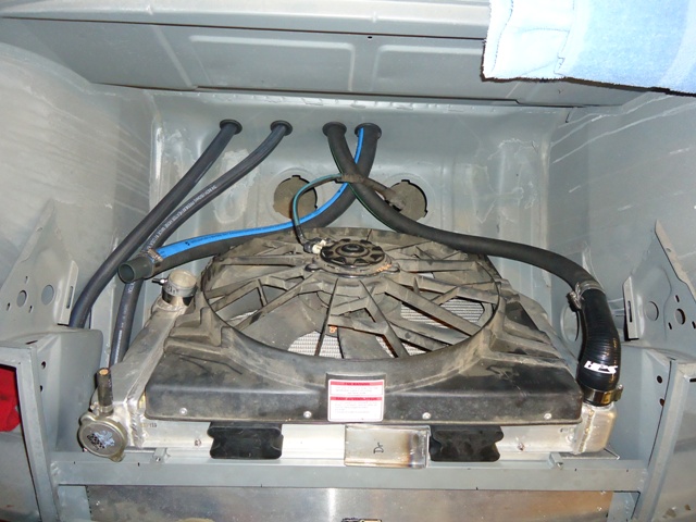 I still have to finish the upper radiator mounts. You'll see the two rubber blocks (Kragen rubber coil spring boosters, part number 18-1701, $7.99), which I'll trim down to fit in the recess on the top of the radiator. Those will be mounted to the metal bracket marked "Dr" that I welded up and will be bolted to the threaded holes on the top of the crossbar. Next up is the picture of the underbody hose routing. Because of the stainless wire in the hose, you need to cut the hose using a thin abrasive wheel; I used a 3" cutter in a die grinder. 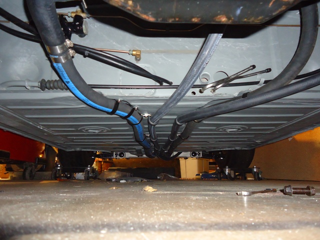 As you can see in the two pictures above, I also finalized the 0.75" air-to-water intercooler hose connections. Again, I used Adel clamps to secure these hoses to the bottom of the car, which I've routed between the two engine coolant hoses. I still need to finalize securing those two hoses at the front of the car and in the engine bay. Below is a picture of the air-to-water filler neck (from a Kawasaki 250). You really don't NEED an overflow for an A-W intercooler, as the temps never get high enough to expand the water, so I'll block of that port. The filler is mounted to a bracket that I welded to the area above the factory battery mounting area. The pump is rubber mounted to a small bracket that I welded to the upper long. 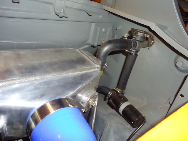 Finally, here is a picture of the engine bay with the air-water intercooler and all turbo piping installed. I welded up stand-off mounts using 3/16" rod, which I'll powdercoat after I finish up mounts for the fuel lines, wiring, etc. I still need to finish up the MAF, air cleaner and related piping/mounts. 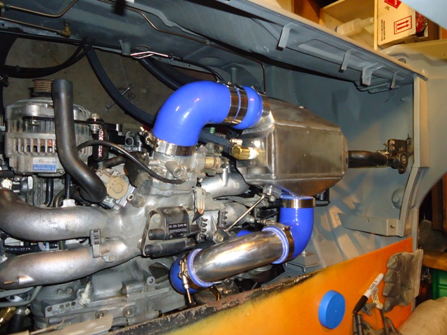 |
|
|
|
| strawman |
Jul 21 2011, 11:37 PM
Post
#205
|
|
Senior Member Group: Members Posts: 891 Joined: 25-January 08 From: Los Osos, CA Member No.: 8,624 Region Association: Central California |
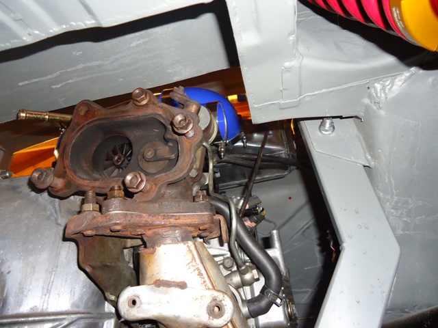
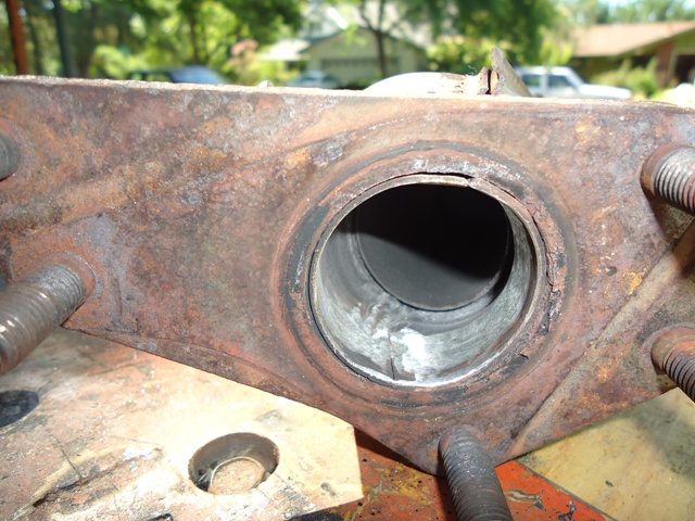
Here is a picture turbo exhaust outlet, which shows the clearance provided by the "box" I welded in the rear trunk floor for the turbo, starter and clutch slave cylinder. It is hard to tell from the photo, but there's about 2.5" clearance above the hot-side of the turbo.
 The next few pics show how anal I can be at times... I am using the stock and HEAVY cast iron exhaust manifolds, at least in the beginning. A lot of the guys on NASIOC complain about SS headers cracking, and how only the stock manifolds can stand up to long-term abuse. Grimmspeed sells ported/polished cast iron manifolds, so I thought I'd give it a go myself 'cause I'm a CSOB. As you can see below in a couple "before" pics, there are some pretty gnarly welds near the flanges of the uppipe. The cast pieces also have some slag and casting marks that could hinder the flow of air to the turbo. What you see below is about four hours' of using a carbide ball bit, stone grinders and a sandpaper roll port-n-polish kit from Harbor Freight. Not sure if it will really make a difference, but I suppose every little bit helps (IMG:style_emoticons/default/beerchug.gif) 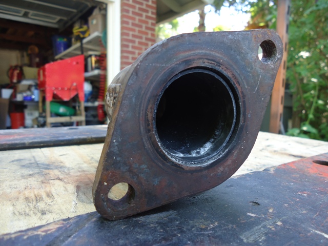 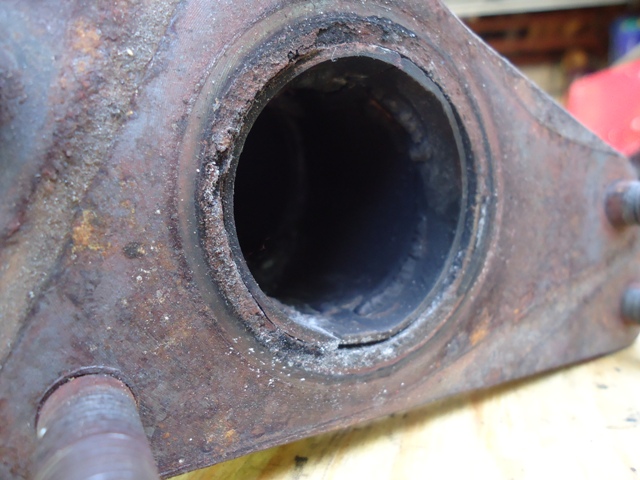 |
|
|
|
| strawman |
Jul 21 2011, 11:49 PM
Post
#206
|
|
Senior Member Group: Members Posts: 891 Joined: 25-January 08 From: Los Osos, CA Member No.: 8,624 Region Association: Central California |
Here are a couple "after" photos.
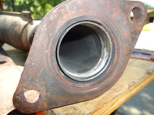  Those were ground down using a carbide ball bit & stone; those will be polished using the port-n-polish rolls (at least I think I bought the kit from HF...). The picture below shows what the final product looks like. 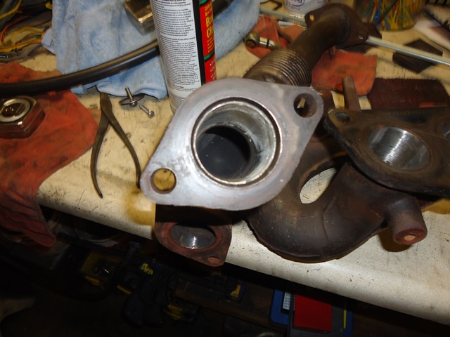 |
|
|
|
| sawtooth |
Jul 22 2011, 12:39 AM
Post
#207
|
|
Member Group: Members Posts: 297 Joined: 25-June 08 From: Boise, ID Member No.: 9,211 Region Association: Intermountain Region |
Looking good. (IMG:style_emoticons/default/smilie_pokal.gif)
|
|
|
|
| strawman |
Nov 6 2011, 07:36 PM
Post
#208
|
|
Senior Member Group: Members Posts: 891 Joined: 25-January 08 From: Los Osos, CA Member No.: 8,624 Region Association: Central California |
Wow, it has been 3 months since my last posting. I guess I really am a slacker...
I finalized my steering setup, which includes raised-spindle Bilstein struts with a lower arm welded on so that I could reduce the tie-rod angle to avoid bumpsteer. I am using 14mm Class 12.9 allen bolts, and found that .750"OD DOM tubing has an ID of .560 -- which works perfectly. I cut some spacers on a lathe that will be mounted above and below the tie-rod end. I will powdercoat the spacers later this week. The tie-rod end was supplied by Elephant Racing, and is a high-quality Aurora heim joint that is extra-long; off-the-shelf ones are too short and would result in extreme toe-in. Below is a pic of all the pieces for one side. 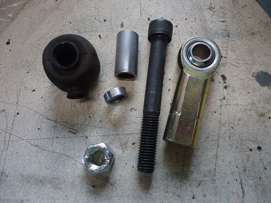 Here is a picture of the setup without the rubber boot, which I bought from a supplier in England. The pic following shows the setup with the boot and upper/lower washers. I still need to drill the allen bolts for a cotter key to use with the castle nut. 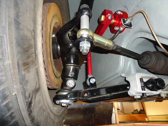 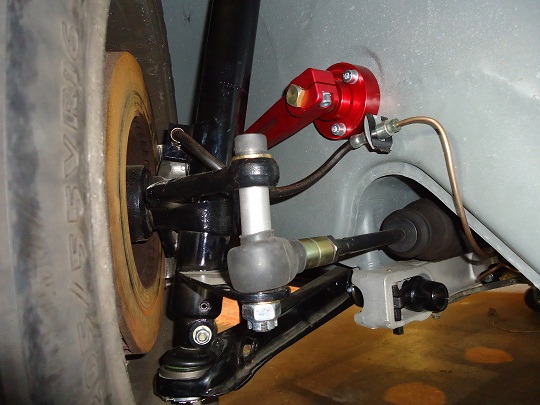 |
|
|
|
| charliew |
Nov 7 2011, 07:57 AM
Post
#209
|
|
Advanced Member Group: Members Posts: 2,363 Joined: 31-July 07 From: Crawford, TX. Member No.: 7,958 |
Looks good Geoff. I guess the arc of the lower a arm moving up is what makes a longer tierod end necessary. How much more travel upward does the a arm have at this setting?
|
|
|
|
| strawman |
Nov 7 2011, 02:20 PM
Post
#210
|
|
Senior Member Group: Members Posts: 891 Joined: 25-January 08 From: Los Osos, CA Member No.: 8,624 Region Association: Central California |
QUOTE(charliew @ Nov 7 2011, 05:57 AM) Looks good Geoff. I guess the arc of the lower a arm moving up is what makes a longer tierod end necessary. How much more travel upward does the a arm have at this setting? Actually, I believe a longer tie-rod end is necessary due to the angle of the hole in the factory steering arm -- it points toward the outside/rear of the car and not directly straight down. Elephant sells the longer heim joint for their raised-spindle setup (mine is homebrewed) for that same reason. The travel should be the same as factory, since the strut and A-arm sits in the same relative verticle position. Raising the spindle on the strut body essentially moves the center of the wheel up (and the car down = lowered) without affecting the suspension geometry. See posts #84 and #93 to see details of how I raised the spindles a little more than one inch. When you use the factory torsion bar adjusters to lower the car, you're changing the angle of the A-arms (relative to the ground), which also exacerbates the tie-rod angles and increases bumpsteer problems. My admittedly copied setup eliminates those problems. |
|
|
|
| strawman |
Jun 19 2012, 09:50 AM
Post
#211
|
|
Senior Member Group: Members Posts: 891 Joined: 25-January 08 From: Los Osos, CA Member No.: 8,624 Region Association: Central California |
Finally, we closed on our new-to-us house in San Luis Obispo and I was able to pull my teener out of storage. Below is a pic of the car on the HUGE equipment trailer I rented (U-Haul couldn't find me a regular car transport within 100 miles!) at the storage facility, and the second shows it sitting proudly in her new home.
It has been over six months since I've laid hands on her... I think I now know what it feels like to be a sailor coming home to his lovely wife after a long stint on the sea! (IMG:style_emoticons/default/grouphug.gif) 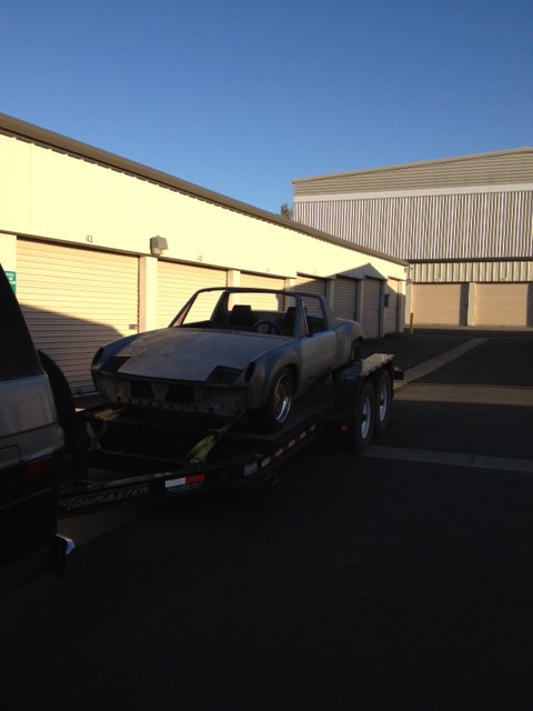 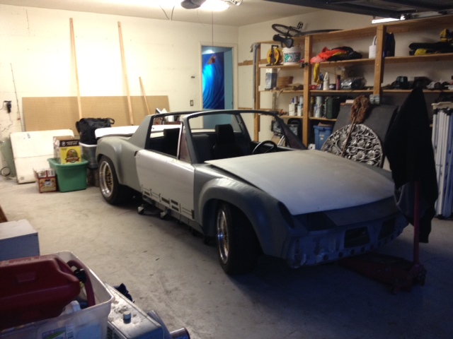 Let the fun begin! Geoff |
|
|
|
| JRust |
Jun 19 2012, 09:54 AM
Post
#212
|
|
914 Guru Group: Members Posts: 6,317 Joined: 10-January 03 From: Albany Oregon Member No.: 129 Region Association: Pacific Northwest |
Congrats on the new place Geoff! Nice to see the teener out of storage too. I can see progress coming much quicker for you now. It's great to be able to run out to the shop for even just a few minutes. Alot easier to get things done when the shop is at your home (IMG:style_emoticons/default/piratenanner.gif) . Get over moving all your stuff & get to work (IMG:style_emoticons/default/first.gif)
|
|
|
|
| Zaney |
Jun 19 2012, 07:01 PM
Post
#213
|
|
Deuchland en der Haus Group: Members Posts: 461 Joined: 1-March 04 From: Engine 11 Redmond, WA Member No.: 1,738 Region Association: Pacific Northwest |
Hooray!
I am so glad that you have finally found a place for your Teener! I am trying to use the John Kelly fender stretching techniques to make my wheels fit. i hope that your new digs suit your family well!!!! Cheers! (IMG:style_emoticons/default/beerchug.gif) Nate |
|
|
|
| ThePaintedMan |
Aug 10 2012, 09:31 AM
Post
#214
|
|
Advanced Member Group: Members Posts: 3,887 Joined: 6-September 11 From: St. Petersburg, FL Member No.: 13,527 Region Association: South East States |
Geoff,
Sorry I hadn't commented on this thread previously. Your work is a thing of beauty. I hope to have the resources one day to do a car "right" like you are. One of the main questions I've always had about Subaru conversions is the gauges. What are you planning to do in this area? Is there any way to preserve the functionality of the tachometer, and alt/fuel gauges in particular? If I was ever to attempt something like this, I would probably keep the 901 transaxle, so the speedo wouldn't be an issue. |
|
|
|
| strawman |
Aug 11 2012, 08:41 PM
Post
#215
|
|
Senior Member Group: Members Posts: 891 Joined: 25-January 08 From: Los Osos, CA Member No.: 8,624 Region Association: Central California |
QUOTE(ThePaintedMan @ Aug 10 2012, 08:31 AM) One of the main questions I've always had about Subaru conversions is the gauges. What are you planning to do in this area? Is there any way to preserve the functionality of the tachometer, and alt/fuel gauges in particular? I am hoping the signal from the Subaru ECU will drive the 914 tachometer, and I plan to obtain an electronic 911 speedo and see if a two-wire Subaru Vehicle Speed Sensor will work. The e-VSS from 1997 & 1998 Forester fits right into the older 5-speed Suby transaxles like mine, replacing the mechanical speedometer drive. I'm eager to find out if it will work, too! |
|
|
|
| Mike Bellis |
Aug 11 2012, 09:21 PM
Post
#216
|
|
Resident Electrician Group: Members Posts: 8,348 Joined: 22-June 09 From: Midlothian TX Member No.: 10,496 Region Association: None |
|
|
|
|
| strawman |
Aug 11 2012, 09:29 PM
Post
#217
|
|
Senior Member Group: Members Posts: 891 Joined: 25-January 08 From: Los Osos, CA Member No.: 8,624 Region Association: Central California |
Finally, I had some time to work on my car -- after about 8 months of inactivity. (IMG:style_emoticons/default/piratenanner.gif)
I spent some time several months ago (!) poring over the wiring diagrams of my 914 and the donor car -- a 1993 Subaru Legacy Turbo -- to chronicle which Suby wires should mate to which 914 wires, and vice versa. I put this into a spreadsheet if anyone is interested. It should be noted that many ECU wires are shielded and are a bitch to alter the length. I figure the Fuji Heavy Industries engineers were prolly a little particular when it came to signal loss, so I decided to place the ECU in a place where no shielded wires had to be lengthened (see pics below), and will loop the ones that are too long. Not as pretty as would be possible if I were willing to risk chopping those shielded cables, but this strategy should avoid some gremlins during the shakedown. Another thing that seems to be a best-practice is to solder wires where possible, followed by a good two-wall heat-shrink (with silicon goop inside!). I've read you should unplug from the ECU to make sure no weird signals are sent upstream, so I did that, too. For those large wires (i.e., 12 gauge or larger), I use either weatherproof crimp connectors ($$) or just use bare crimp barrels followed by good heat-shrink. Where there is a possibility that the wires might face extreme vibration or other stress, I double the heat-shrink. Maybe I'm being too paranoid and over-engineering things, but this has worked for other engine swaps I've completed in the past. Furthermore, I work in the public transit world, and the good buses are built using those practices, while the ones I overpay towing companies to haul back to our shop use the cheap non-weatherproof connections that make my mechanics pull their hair out. 'Nuff said... This isn't merely a mating of two harnesses; that would be too easy. So you have to improvise and plan for what you're trying to accomplish. For example, I ran an 8 gauge wire through the 914 loom from the battery to the radiator fan controller in the front trunk, as well as a couple of other new wires I knew I'd need (vehicle speed sensor for an electronic speedo, in-tank fuel pump, etc.). I also know that I cannot envision what other electronic items I might add in the future. So I ended up running five extra 16 gauge wires from the engine bay to the fuse box area (with an extra 5' at the fuse box end), as well as one extra 14 gauge wire from the engine bay to the front trunk. I have a small hill of wires I cut out of the Suby harness and the 914 harness. I recommend keeping every wire you remove, since you might need them later to have a same-color splice as you progress in this type of project. I also used a Delco Weatherpack system that will permit me to remove stuff without cutting wires in the future. I'll show a close-up of the 6-port system I used later on. The first picture shows how everything is laid-out, as well the copious amount of marking I use to make sure I'm hooking up the correct wires (measure twice, cut once, check again, then connect). I like to use high-quality green or blue masking tape and a Sharpie to signify where it comes from on one side and where it goes to on the other side. Do yourself a favor and use scissors to trim the tape tags -- if you leave 'em ragged they'll catch on stuff and end up falling off. You can also see the small Braille battery I'm running. I thought about mounting it low on the cabin-engine bay firewall, but I'd have to run a long (and relatively heavy) cable back to the starter -- so I figured I'd keep it close to the ECU where it is easily accessible. As you can see, I'm running the wires through the targa top cup holes; I still hafta figure out grommets to protect the looms. 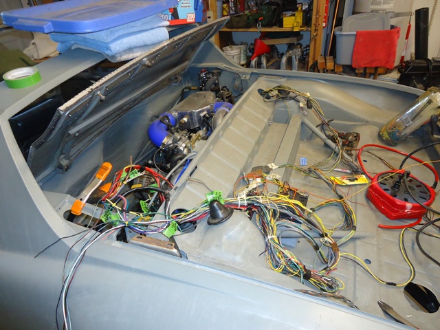 The second picture shows the cabin area, prior to mounting the updated fuse-panel or running the loom through the front firewall to the front trunk. You can see the big-ass red 8-gauge radiator fan wire coiled up on the driver's seat, as well as the 14ga blue wire for the fuel pump / spare 14ga black wires for the frunk coiled next to it. You can also see the extra five wires draped over the door. Technicolor spaghetti love, eh? 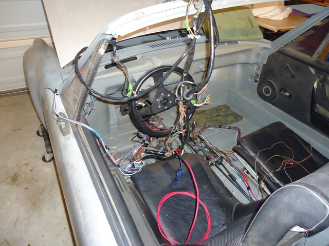 The third picture shows the connections made from the Suby ECU/engine loom mated up to the 914 loom. Doesn't look like much, but there is easily 15 hours of head-scratching and pinched-ass labor between pictures 1 & 3. 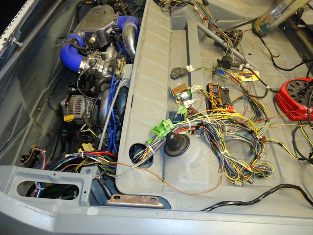 The fourth picture shows the driver's area taking shape, after feeding the loom through the front firewall into the frunk. You'll note that I screwed up and neglected to feed the engine loom through the first tunnel hole (next to the shifter setup) -- that'll have to do until I tear it all apart again to paint it in the (hopefully near!) future. 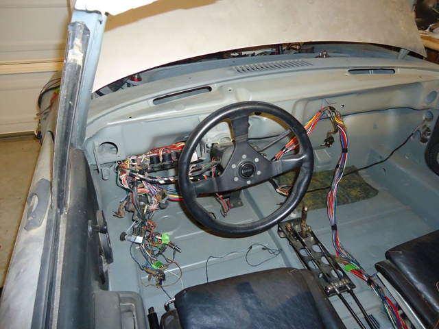 The final picture shows the Weatherpack system all sealed up. It requires some specialized tools, and the 18 and 20 gauge wires are a beeyotch to get right. But it is an OEM quality connection. 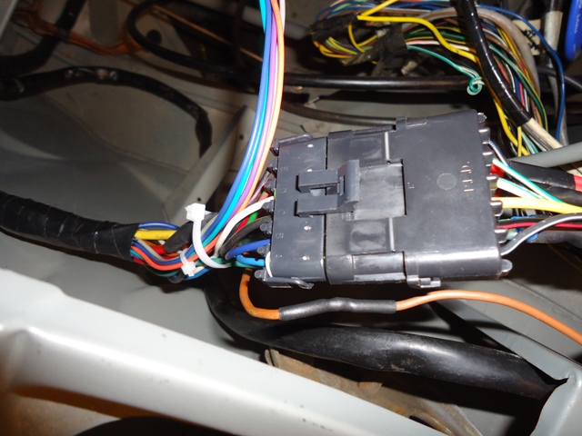 I still need to mount a few electrical components in the trunks, and to finalize the vacuum tubing. I could not fit the electronic HKS boost controller (thanks Jim Dupree!) wiring loom into the 914 wiring loom and still get it through the tunnel/firewall hole, so I'm gonna hafta drill through the cabin-engine bay firewall for that 8-wire loom. Then comes the exhaust system and final cabin wiring that will permit to start it up for the first time. Yay! |
|
|
|
| 76-914 |
Aug 12 2012, 12:11 PM
Post
#218
|
|
Repeat Offender & Resident Subaru Antagonist Group: Members Posts: 13,883 Joined: 23-January 09 From: Temecula, CA Member No.: 9,964 Region Association: Southern California |
Great thread. I'm sure I will be reading it again. (IMG:style_emoticons/default/biggrin.gif) Yes, I would be interested in a copy of the spread sheet you came up with, please. I was going to ask you if the shoulder of those allen bolts carried through until I read what you do for a leaving. Never mind. (IMG:style_emoticons/default/lol-2.gif) I'm thinking A/C also so I'll be curious as to which system you employ. (IMG:style_emoticons/default/popcorn[1].gif)
|
|
|
|
| strawman |
Aug 12 2012, 01:15 PM
Post
#219
|
|
Senior Member Group: Members Posts: 891 Joined: 25-January 08 From: Los Osos, CA Member No.: 8,624 Region Association: Central California |
Attached is a PDF of the Suby-914 wiring spreadsheet if anyone is interested. Hope this works...
 Wiring_harness__Suby_Legacy_Touring_to_Porsche_914_11_Aug_2012.pdf ( 19.32k )
Number of downloads: 420
Wiring_harness__Suby_Legacy_Touring_to_Porsche_914_11_Aug_2012.pdf ( 19.32k )
Number of downloads: 420If you have trouble opening it or if you'd like it in an MS Excel format, PM me your email addy. |
|
|
|
| strawman |
Sep 24 2012, 09:05 PM
Post
#220
|
|
Senior Member Group: Members Posts: 891 Joined: 25-January 08 From: Los Osos, CA Member No.: 8,624 Region Association: Central California |
Wiring cuts/pastes are finally done; now I need to hook up everything forward of the firewall. In the meantime, I finalized my exhaust. I picked-up a stainless steel Invidia divided-bellmouth dumptube from a guy on Craigslist that went off-roading in his WRX by accident. The bottom was crushed-in, but I only needed the bellmouth and a few inches of the downtube -- so it was $20 well spent. I also picked up a mandrel-bent J-bend Pypes stainless steel piece from Jeg's and a shorty stainless Flowmaster (p.n. 843015) muffler to finish out the system.
Here is the bellmouth that shows the divide. I am using an internal wastegate that blows the over-boost from my TD05-16G turbo into the dumptube. 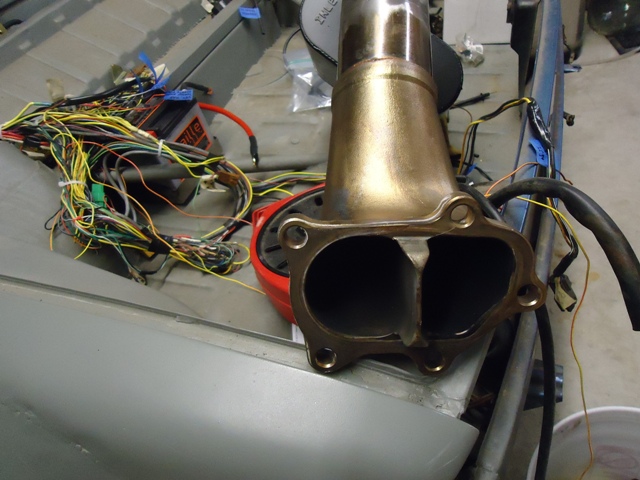 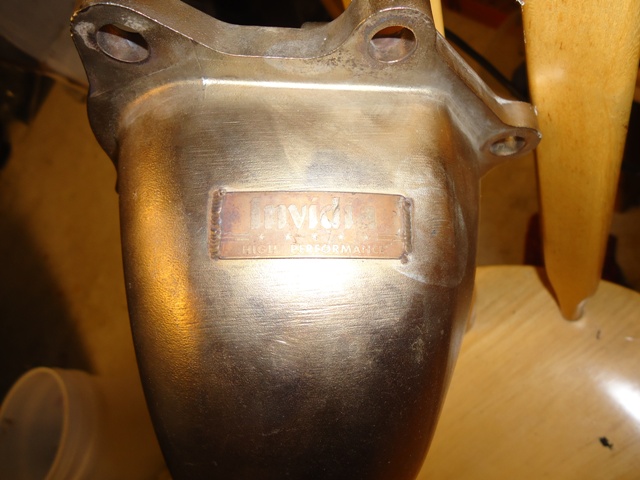 Next up are a couple pics of the exhaust mocked up. After a bunch of careful measurements and a few cuts, below is what I ended up with. My neighbor has a nice TIG machine, so he tacked it up for me after I marked & taped (!!) everything together. 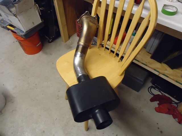 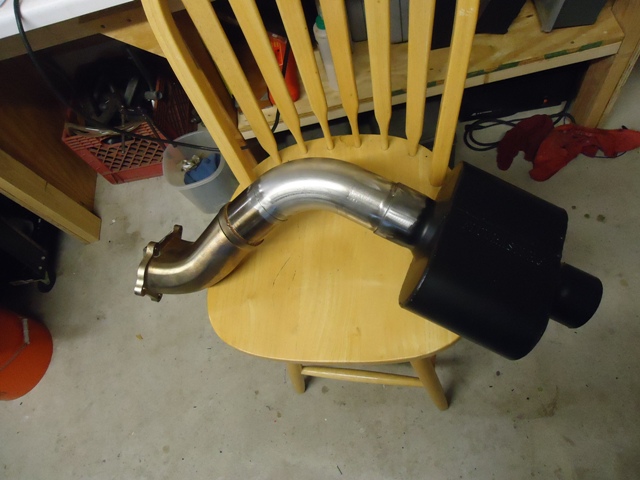 Here it is bolted in and tucked-up out of harm's way. Still need to devise a muffler support and an outlet tip. For the former, I'll bolt the muffler support to the transaxle, since the whole engine/trans/exhaust will move as a single unit in the engine/trans mounts. 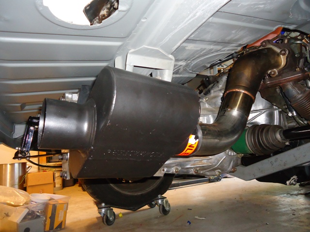 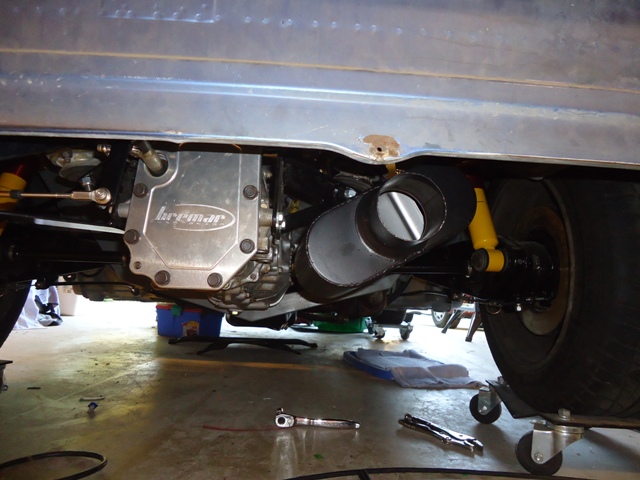 I still need to cut-in two sensor bungs -- one for the stock narrow-band oxygen sensor and one for a wideband sensor. I've somehow lost the two SS sensor bungs during my move, so I'll order a couple more tonight. Once I get them mocked-up, I'll walk it over to Bill so he can do his TIG magic... |
|
|
|
|
2 User(s) are reading this topic (2 Guests and 0 Anonymous Users)
0 Members:

|
Lo-Fi Version | Time is now: 17th May 2026 - 09:04 AM |
Invision Power Board
v9.1.4 © 2026 IPS, Inc.