|
|
|
Porsche, and the Porsche crest are registered trademarks of Dr. Ing. h.c. F. Porsche AG.
This site is not affiliated with Porsche in any way. Its only purpose is to provide an online forum for car enthusiasts. All other trademarks are property of their respective owners. |
|
|

  |

| strawman |
 Dec 20 2018, 12:51 PM Dec 20 2018, 12:51 PM
Post
#401
|
|
Senior Member  Group: Members Posts: 891 Joined: 25-January 08 From: Los Osos, CA Member No.: 8,624 Region Association: Central California |
Last weekend I finished up the fueling system, and dropped off my custom-made filter & E85 firewall mounts at the powdercoater on Monday. Once I get those back, I will mount everything up and show how it ties into my Tangerine Racing stainless fuel lines. I also carved out some time last night to assemble the long-block, after needing to buy some more small parts (gaskets, spacers, etc.) before mounting the heads. I also had to pick up my rebuilt Active Valve Control System (AVCS) cam gears from Pokrajac Motorsports. Below are some pictures.
Here is the right side of the short-block; you can see the ARP studs and OEM head gasket, as well as the side of the SmallCar cast aluminum oil pan. 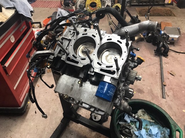 Next up is the right side head with the cams/caps removed, the ARP hardened washers installed, and ready to be torqued onto the block. ARP calls for three stages: 30 ft/lbs, followed by 60 and then 90. 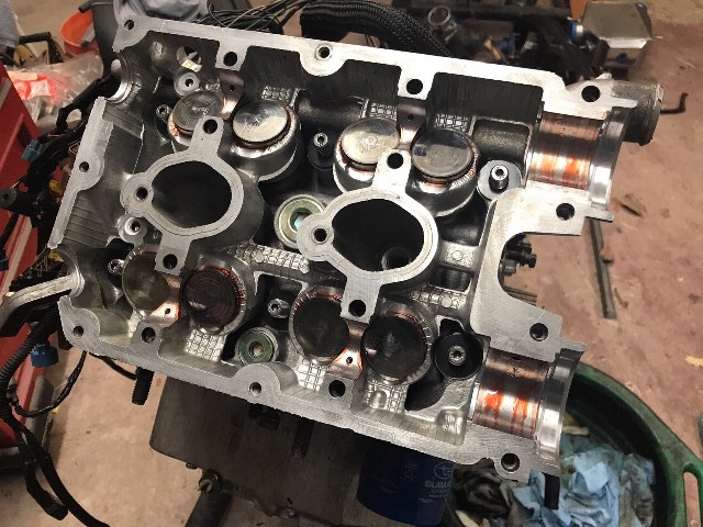 Here are the cams and caps bolted on. The intake (upper) cam uses a hydraulically controlled solenoid to advance the timing under higher load/rpm situations. Subaru's AVCS system is somewhat similar to VANOS (BMW) or VTEC (Honda). I used Permatex Ultra Gray for the forward caps for both pressurizing and leak prevention. 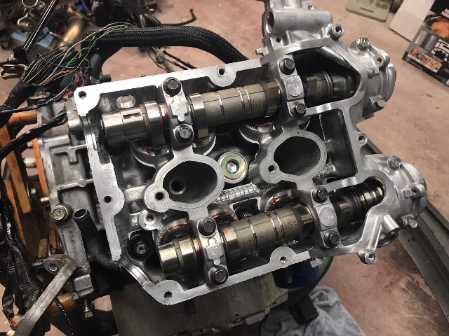 The pics below show the valve cover mounted, the final long-block assembly, and then the cam gears -- including the AVCS intake gear -- on the left side. Before I called it quits last night, I mounted the right side cam gears, TGV-deleted intakes, AVCS solenoids. oil feeder lines, cam sensors, and a few other items. I hope to find time tonight to install the OEM timing belt and covers, and to wrap up the engine wiring harness, exhaust/turbo mounting/etc. 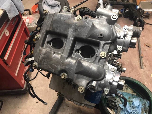 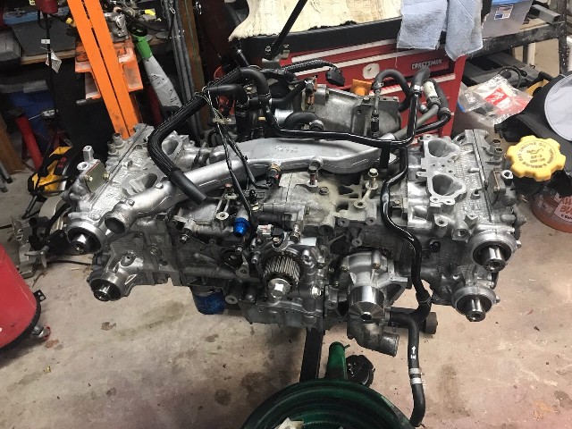 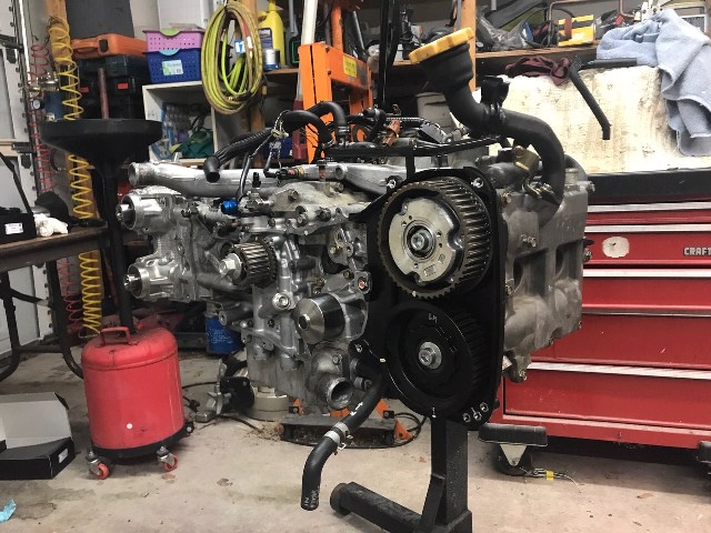 I still need to weld up the final intercooler piping, the Tial blow-off valve and bungs for speed-density/air-intake sensor, which I will tackle after visiting my folks in my hometown of San Francisco for the holidays. Happy Holidays to you all! |
   |

 
|
| 76-914 |
Dec 20 2018, 02:18 PM
Post
#402
|
|
Repeat Offender & Resident Subaru Antagonist Group: Members Posts: 13,883 Joined: 23-January 09 From: Temecula, CA Member No.: 9,964 Region Association: Southern California |
How much HP do you expect to gain with this set up vs. the old engine? Did you spring for Outfront's reinforcement kit fr the open deck? I've read those studs are the ticket! (IMG:style_emoticons/default/popcorn[1].gif)
|
|
|
|
| Chi-town |
Dec 20 2018, 02:36 PM
Post
#403
|
|
Senior Member Group: Members Posts: 851 Joined: 31-August 18 From: Disneyland Member No.: 22,446 Region Association: Southern California |
stock EJ255, stock heads and cams, modded VF40, AWIC on E85 should be in the 330-360whp range.
I would consider having the block bored and honed with a forged piston set to avoid issues long term. Broken ring lands are no fun. |
|
|
|
| effutuo101 |
Dec 20 2018, 08:12 PM
Post
#404
|
|
Advanced Member Group: Members Posts: 2,738 Joined: 10-April 05 From: Lemon Grove Member No.: 3,914 Region Association: Southern California |
I dyno at over 300 torque (2800rpm) and 280 hp with my small G20. Cant wait to get the car on the road and finish break in. Next up is a different spool to move the curve up a bit.
Same 2.5 16v motor. |
|
|
|
| strawman |
Dec 24 2018, 10:40 AM
Post
#405
|
|
Senior Member Group: Members Posts: 891 Joined: 25-January 08 From: Los Osos, CA Member No.: 8,624 Region Association: Central California |
Based on the mods I’d done to the previous engine, I believe it made 200 whp. I will “detune” this current engine to be about 300 whp so that I don’t stress it too much using the stock pistons. If (when?!) I blow it, I’ll go with a Stage 2 closed deck short block and turn up the wick a bit. Honestly, it starts to get a little silly with too much horsepower and limited tire size even with flares. I could easily spin 200 treadwear tires in second gear with the old engine...
|
|
|
|
| strawman |
Dec 31 2018, 05:37 PM
Post
#406
|
|
Senior Member Group: Members Posts: 891 Joined: 25-January 08 From: Los Osos, CA Member No.: 8,624 Region Association: Central California |
No matter how many times you measure, you never really know if everything is going to fit until you mock it up. In other words, all good planning is rewarded with setbacks... (IMG:style_emoticons/default/headbang.gif)
Below is a picture of the long-block and transaxle mated up on my engine cradle, including the newly-powdercoated engine mount "U-bar" and trans mount. I started by using my cherry-picker to lift the engine from the engine stand to the cradle, and then using it to help mock the transaxle up to the engine (no flywheel yet). 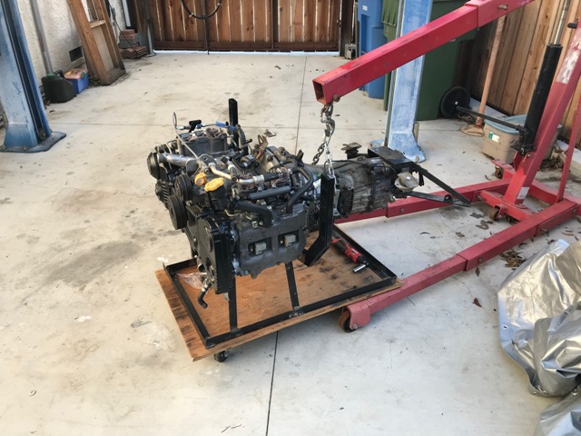 The next pic is of the car getting ready to gobble it up. 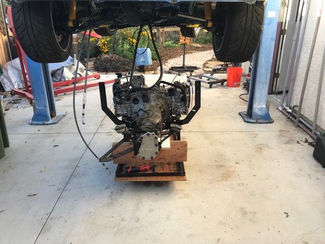 I ended up having to remove the U-bar so that I wouldn't scratch it up on the rear trailing arms during the car lowering process; I used yellow painter's tape that you can see in the pic below to protect everything. With the help of my lovely wife, we fished/guided the U-bar in place after roughing up the location of the engine in the chassis. It took me about 90 minutes from the time I cherry-picked the engine from the engine stand until the engine/trans were fully mounted in the chassis. 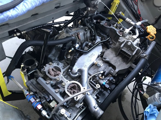 Now you can see where I ran out of space (talent?)... 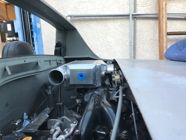 The intercooler inlet (passenger side of engine bay pointing to the rear of the car) could technically work by massaging the engine/trunk firewall and clearancing the engine lid cross-brace. However, the problem is the throttle body's orientation -- it aims at an upward-and-to-the-right angle directly at the bracing for the engine lid latching system. Three solutions are possible: 1) move the engine lid latch mechanism and bracing, and build "boxes" for the clearance needed on the engine bay/trunk firewall; 2) flip the plastic intake manifold 180 degrees; or 3) move the intercooler to the trunk. Option 1 would result in maximizing trunk space, and I already have all of the silicone couplers and aluminum tubing. But is requires a lot of fabrication and would still be VERY tight. Option 2 will require new alternator and air conditioning compressor mounts in order to also maximize trunk space, but will require a lot of new tubing work, rewiring, etc. Option 3 also requires new tubing, since it will open up the engine bay and ensure the shortest intercooler tube routing. But it further reduces trunk space. I've opted for number 3. Since my engine tuner recommends that, instead of using 3" intercooler tubing throughout, I use 2" tubing and step it up for the 3" OD intercooler in- and outlets. The smaller tubing size also apparently helps maintain charge-air speed within the intake system while also requiring less physical space. I've already ordered all of the necessary tubing, silicone couplers, clamps and other assorted items. Hopefully, everything arrives in time to dive in next weekend. In the meantime, I'll wrap up the fueling system, ECU mounting, wiring and reworking of the AWIC hose routing. Stay tuned! |
|
|
|
| Tdskip |
Jan 1 2019, 07:52 AM
Post
#407
|
|
Advanced Member Group: Members Posts: 3,782 Joined: 1-December 17 From: soCal Member No.: 21,666 Region Association: None |
QUOTE(strawman @ Dec 24 2018, 11:40 AM)  Based on the mods I’d done to the previous engine, I believe it made 200 whp. I will “detune” this current engine to be about 300 whp so that I don’t stress it too much using the stock pistons. If (when?!) I blow it, I’ll go with a Stage 2 closed deck short block and turn up the wick a bit. Honestly, it starts to get a little silly with too much horsepower and limited tire size even with flares. I could easily spin 200 treadwear tires in second gear with the old engine... That is a lot of power! |
|
|
|
| charliew |
Jan 1 2019, 12:35 PM
Post
#408
|
|
Advanced Member Group: Members Posts: 2,363 Joined: 31-July 07 From: Crawford, TX. Member No.: 7,958 |
I know you have done a lot of research on these mods but I thought about the oil restrictor in the head for the factory turbo. I have read in the far past about too much oil in the turbo getting into the air path. Do you have or need a restrictor in this new setup? e85 is a lot of work and expense, I know it is for the future though especially all out performance on the track. I probably missed a part about maybe a dual disk clutch and lighter flywheel? or just new factory parts?
|
|
|
|
| 914forme |
Jan 1 2019, 01:01 PM
Post
#409
|
|
Times a wastin', get wrenchin'! Group: Members Posts: 3,899 Joined: 24-July 04 From: Dayton, Ohio Member No.: 2,388 Region Association: None |
Oil in the pathway does happen, I have used the Mann Provent 200s in all my turbo diesels and Scott's PORSTI build used one, they do pretty much eliminate the issue of oil in the intake. And they let all the "bad stuff" pass as intended.
Scott's prevent drains down into the dips stick tube. I have one on my ML320 right now, and I just have a valve, I drain it once a week, and I am collecting al the drainage to see how much oil I have recovered between oil changes. If I get into quarts I will drain it back to the engine, if not, I will leave it as is. My drain hose is about 2 get long, with a ball valve mounted low. Also your solution to your intercooler is is an air to water unit, packaging is smaller, can be mounted out of the way with no airflow requirements. |
|
|
|
| strawman |
Jan 2 2019, 11:40 AM
Post
#410
|
|
Senior Member Group: Members Posts: 891 Joined: 25-January 08 From: Los Osos, CA Member No.: 8,624 Region Association: Central California |
I spent a (admittedly) hazy New Year's Day working on my teener; I was overserved the night before with friends at an English Beat concert. (IMG:style_emoticons/default/drunk.gif)
The more I looked at the idea of the intercooler (I/C) in the the trunk, the less I liked it. My main concern was the extremely short turbo outlet to I/C tract -- such a rigid connection will eventually damage the turbo with engine movement. I came up with a new I/C mounting system that will keep it mounted to the engine within the engine bay; those parts are on order and should be here early next week. I've essentially moved the I/C toward the passenger side and lowered it, while the tubing to the throttle body wraps around (rather than over) the plastic intake manifold on the driver side. I'll have to redo the I/C coolant pump-n-plumbing, but that is relatively easy. However, with all of these starts-n-stops on the I/C mounting design, there's gonna be a big pile of new & unused parts. (IMG:style_emoticons/default/sheeplove.gif) I also fabricated a mounting system for my IAG Performance air-oil separator (AOS) system. The IAG AOS is highly regarded in the Subaru world, although it is over $400 after taxes and shipping. Many race setups vent crankcase vapors to atmosphere, but when using ethanol, IAG recommends their "street" setup that uses the engine's vacuum to help evacuate corrosive ethanol fumes from the crankcase. It is a beautiful piece of machinery, although it looks like a spider with all the hoses coming out of it -- and that makes packaging in the 914 engine bay even more challenging. It uses engine coolant to heat the AOS chamber, which helps vaporize the moisture and "scrub" the air that goes into the intake tract (pre-turbo); the gathered oil is drained back into the crankcase. I'm happy with the mocked-up mount I devised (about four hours' worth of work) yesterday; I'll snap some photos when it is all set up. Charlie, I'm running a separate/mini oil filter with the correct-sized restrictor from the block to the turbo. Suby engines are apparently pretty rough on turbo oiling, so I didn't want to risk early failure. In fact, BNR Performance will only warranty their turbo if you abide by their oiling requirements. I'm running a lightened flywheel with a Stage II sprung clutch. It held up well with my previous EJ22T with hard launches and other general abuse. I made the mistake of powdercoating my engine U-bar mount, and my new Grimmspeed uppipe to the turbo rubs against it. (IMG:style_emoticons/default/stromberg.gif) (IMG:style_emoticons/default/headbang.gif) I'll need to notch out a bigger channel than the one that worked for my old EJ22T's uppipe, and weld-in a larger reinforcement. Then I'll get it blasted and powdercoated again. It was "pretty" for a while... |
|
|
|
| strawman |
Jan 11 2019, 11:14 AM
Post
#411
|
|
Senior Member Group: Members Posts: 891 Joined: 25-January 08 From: Los Osos, CA Member No.: 8,624 Region Association: Central California |
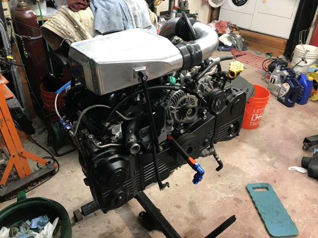
I removed the engine/trans last weekend, and devised the new air-water intercooler (AWIC) mounting system. First up is a picture of the old AWIC setup, which as described in earlier posts sat too high and too far back. As you can see, I used 3" tubing and the charged-air pathways were very short/direct. You can also see that I powdercoated the mounts, which are now beautiful and time-sucking paperweights. (IMG:style_emoticons/default/mad.gif)
 The new mounting setup moves the AWIC lower and forward, as shown below. The charged-air pathways are slightly longer than the old setup, but the smaller 2" diameter tubing will apparently help with maintaining airspeed and throttle response. I'm using 1/2" OD steel tubing for the three AWIC mounts because of its strength and relative lightness, as well as a few cool counterbored bungs that allow use of stainless allen-head bolts. It takes extra time to fish-mouth each joint, but it is strong and cool-looking. You can see the yellow tape-protected piece of 2" intercooler tubing that comes from the drive-by-wire throttle body and wraps around/over the plastic intake manifold; I'm waiting on delivery of a 30 degree mandrel bend tube that I'll weld in to connect it to the black silicone coupler on the AWIC. You can also see my fuel feed/inlet mounting (the black y-shaped fitting on the "pedestal") and the Aeromotive adjustable fuel pressure regulator (FPR), which is the outlet back to the tank. That portion of the mount also provides protection from a failed alternator or A/C compressor belt. That is particularly important for the -10AN Accusump feed line that goes into the front of the block (you can barely make-out the black 45 degree fitting), as well as the fuel lines. I'm running 3/8" feed and 5/16" return for the fuel lines, which my tuner says is the bare minimum for my horsepower goals. The doohickey on top of the FPR is an electronic pressure sensor, which feeds info to the COBB AccessPort and will pull timing / reduce boost if the fuel pressure drops below a preset threshold... this helps prevent lean-running under load and can save the engine. 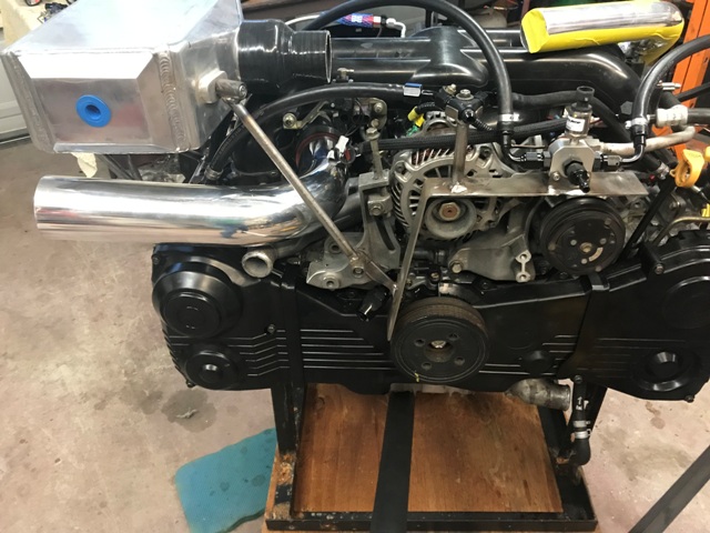 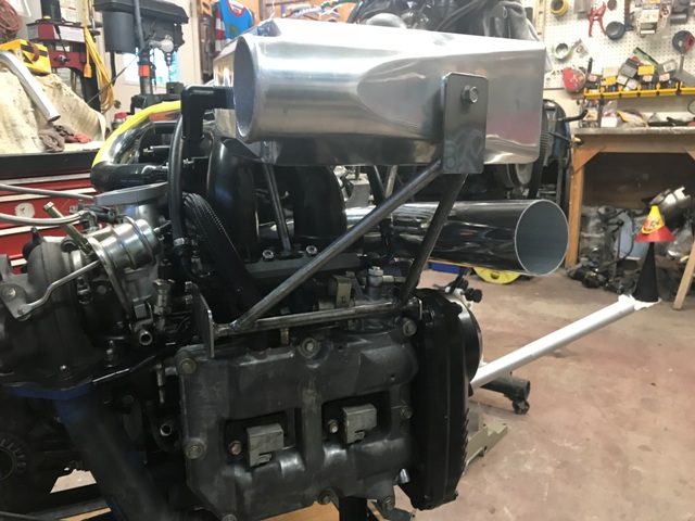 From the side view above, you can see the relatively elaborate "cage" I fabricated for the outer mount. I will add a mount for the engine wiring harness plug to this cage once I finalize the wiring this weekend. You can also see the 90 degree tube that will connect a large K&N cone air filter to the turbo inlet. I still need to weld on some mounting tabs to this big tube, as well as a couple nipples for the Air-Oil Separator system hoses. What's next? I need to weld a small bung onto the charged-air pipe for the speed density sensor and a large one for the Tial blow-off valve. I hope Brown Santa comes today to deliver materials for the custom flange I'll fabricate to mount on the turbo outlet, which will connect to the inlet side of the AWIC. |
|
|
|
| 76-914 |
Jan 11 2019, 04:56 PM
Post
#412
|
|
Repeat Offender & Resident Subaru Antagonist Group: Members Posts: 13,883 Joined: 23-January 09 From: Temecula, CA Member No.: 9,964 Region Association: Southern California |
So close to driving it. Cool stuff. (IMG:style_emoticons/default/popcorn[1].gif)
|
|
|
|
| strawman |
Feb 8 2019, 11:51 AM
Post
#413
|
|
Senior Member Group: Members Posts: 891 Joined: 25-January 08 From: Los Osos, CA Member No.: 8,624 Region Association: Central California |
Spent many an evening, weekends and vacation days (and strains on my marriage!) to get the car ready for an autocross this weekend. But at 8:30 last Sunday, I finally threw in the towel. The next race is March 2nd, so I have a new deadline...
Here are some pictures of my progress. First up are some firewall pics showing my Cobb FlexFuel (E85) fueling setup & fuel filter, then the hole for the wiring harness, and then my grommet solution for the shifter cables. The grommet for the shifter cables came out of a late-80s Toyota pickup -- essentially a blank rubber plug and a metal mounting "frame". I put the rubber plug in the freezer overnight to harden it, and then drilled it at the appropriate angle for both cables. 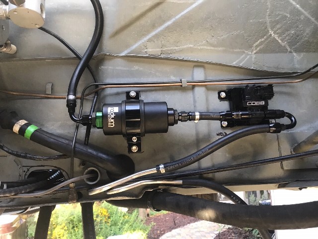 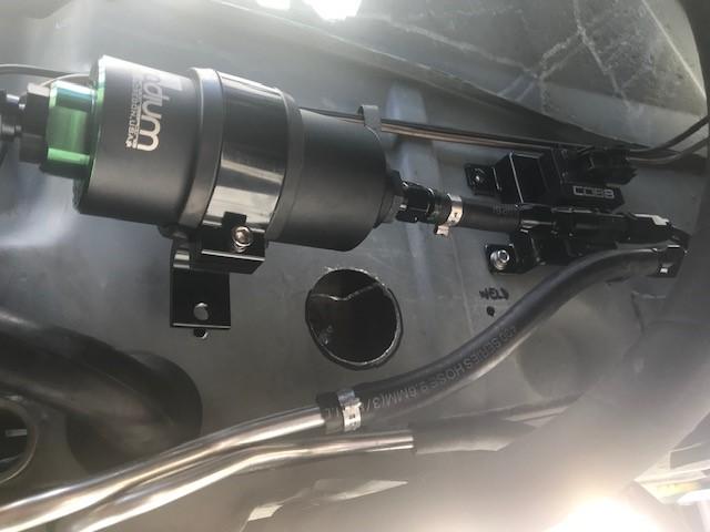 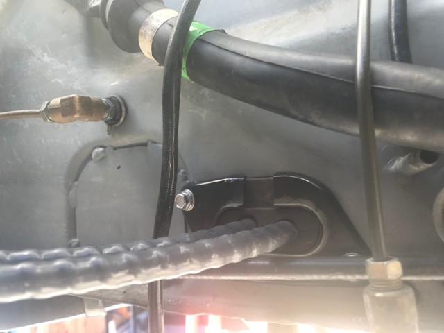 Next up are some pics of my accelerator solution. The EJ255 uses a drive-by-wire throttle, which is essentially just a big potentiometer. Some guys have mounted the stripped-down potentiometer in the engine bay and actuate it with the throttle cable. But since I'm mounting the ECU in the cabin, the factory wires and grounding shields would reach. Below show where I welded in the mounts for the pedal assembly. I also had to heat up and bend the pedal arm to make it fit. I am happy with the placement, and -- at least in my garage -- it will allow good heel-toe action. 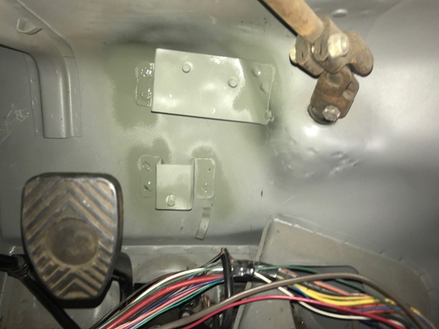 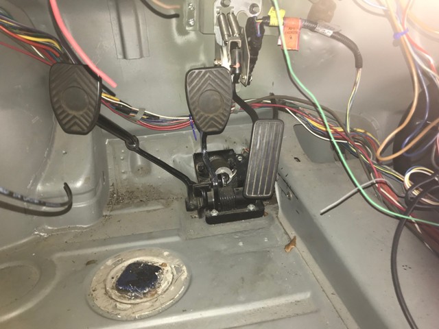 The next pictures show the engine wiring harness mounted on the engine without the turbo, intercooler or piping. You can see the firewall grommet sitting on the table -- it is from a 1991 Lexus LS300. I spent a couple hours in a Pick-n-Pull violently tearing out grommets, and this one seemed the best option; it has a metal mounting frame, has a snorkel on both sides, and the mid-section is long enough to span the firewall cavity. It was only $5, but it required a lot of swearing, wire slicing and cuts to my hands. I ended up slicing the grommet lengthwise to go over my wire bundle and used 3M 4799 Industrial Black Rubber Adhesive (elephant snot). I tested this goo on a spare grommet and let it set overnight. I tried to pull it apart but literally tore the rubber next to it. One trick I learned is to use narrow gauge SS wire in each pleat to line up the rubber while it cured. I'm really happy with the results but didn't take any pictures. 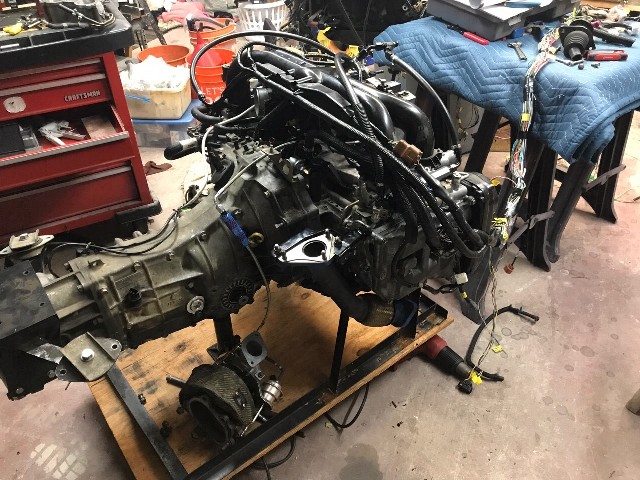 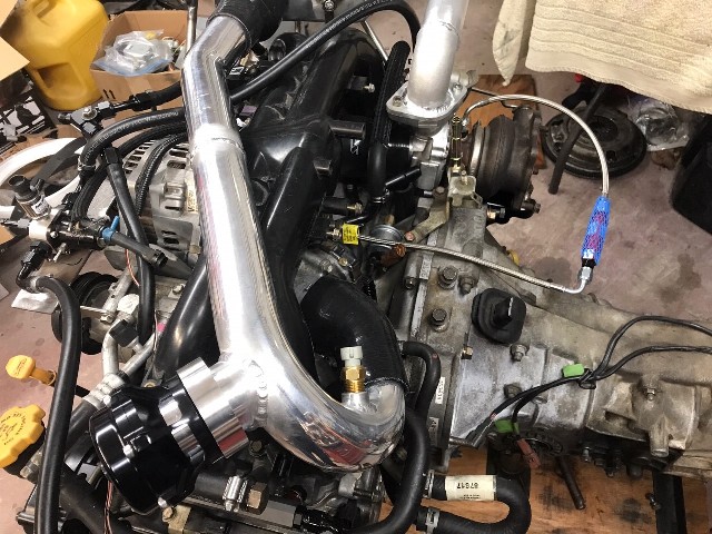 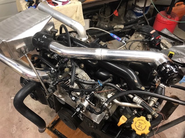 You can see the Intake Air Temp sensor on the intake piping near the throttle body; it is from a GM car. This sensor will be used for my speed-density setup, which allows me to delete the factory Suby Mass Air Flow sensor. You can also see the Tial blow-off valve, which is right behind my ear. Yes, it will probably be too (boy racer) loud but I couldn't find another suitable place to mount it. The turbo outlet pipe is also in a raw form; I hadn't yet cut it and beaded the end for the silicone elbow into the intercooler. More on that later... Below is a final picture of the engine in the car, followed by an early stage of bringing the wiring into the cabin. I ended up making a metal frame for the grommet and screwing it into the firewall (cavity). A word of advice -- avoid the shitty SS screws from Home Depot! Two stripped (I should have stopped at that point!), and the third broke off in the hole. I was able to fight out the broken piece, and bought quality screws at Ace Hardware when it opened the next morning. 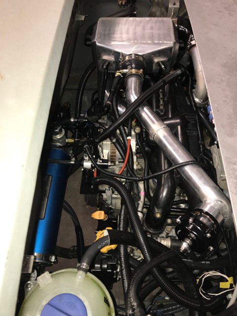 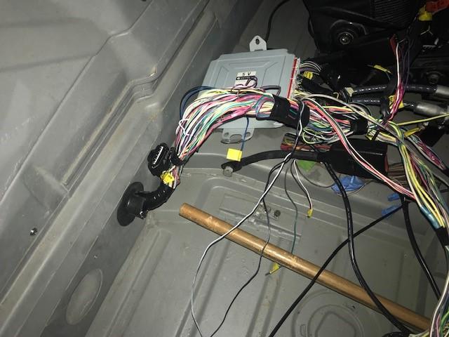 The 90 degree silicone elbow from the 2" turbo outlet tube to the 3" inlet of the intercooler is only 1/8" from the hole for the targa roof cup hole. So I plan to cut off the 3" inlet, weld on a plate, and weld a tight 2" cast aluminum elbow to provide more room. The intercooler piping also interfered with the engine lid latch cable tube -- so I cut out the mount for the cable tube and pushed it back out of the way. I'll need to devise a new system, but will at first just run without the engine lid. This weekend I will finish up the wiring, flash the new ECU code and turn the key. Wish me luck! |
|
|
|
| 76-914 |
Feb 9 2019, 10:08 AM
Post
#414
|
|
Repeat Offender & Resident Subaru Antagonist Group: Members Posts: 13,883 Joined: 23-January 09 From: Temecula, CA Member No.: 9,964 Region Association: Southern California |
|
|
|
|
| rhodyguy |
Feb 9 2019, 10:52 AM
Post
#415
|
|
Chimp Sanctuary NW. Check it out. Group: Members Posts: 22,252 Joined: 2-March 03 From: Orion's Bell. The BELL! Member No.: 378 Region Association: Galt's Gulch |
Very cool. Did you do valve guide work on the heads? That 4799 might be the hot ticket for splitting and replacing the wire bundle snorkel in the engine compartment.
|
|
|
|
| strawman |
Feb 11 2019, 12:03 PM
Post
#416
|
|
Senior Member Group: Members Posts: 891 Joined: 25-January 08 From: Los Osos, CA Member No.: 8,624 Region Association: Central California |
Again, I failed to finish the wiring this weekend. I am a local PCA autocross instructor, so I spent all day Saturday for the clinic at the Santa Maria Airport. That only left me a few hours on Sunday. I finished wiring in the Fuel Temp Sensor, Fuel pump relay bypass (actually, the factory relay triggers a larger-capacity one in the frunk, which allows larger-gauge wire to run the pump through a rewired Fuel Pump Controller), wired the AWIC pump, and bent up a mount for a combo fuse panel and factory relays at the ECU inside the cabin. The plan now is to finish up the wiring and revised turbo-to-AWIC piping this week, and hopefully start it next weekend.
|
|
|
|
| strawman |
Feb 11 2019, 12:05 PM
Post
#417
|
|
Senior Member Group: Members Posts: 891 Joined: 25-January 08 From: Los Osos, CA Member No.: 8,624 Region Association: Central California |
QUOTE(rhodyguy @ Feb 9 2019, 08:52 AM) Did you do valve guide work on the heads? Yes, I had Outfront Motorsports completely rebuild the heads to stock specs. They look beautiful and the valve clearances were spot-on. |
|
|
|
| strawman |
Mar 14 2019, 08:09 PM
Post
#418
|
|
Senior Member Group: Members Posts: 891 Joined: 25-January 08 From: Los Osos, CA Member No.: 8,624 Region Association: Central California |
First start today after a lot of struggles with wiring and tune. My tuner has been VERY patient with me through all of these struggles. Good news is that I’ve got good oil pressure and no untoward noises. Here is the video:
YouTube Video |
|
|
|
| 76-914 |
Mar 15 2019, 09:17 AM
Post
#419
|
|
Repeat Offender & Resident Subaru Antagonist Group: Members Posts: 13,883 Joined: 23-January 09 From: Temecula, CA Member No.: 9,964 Region Association: Southern California |
Mind sharing the re-flash of the ECU? (IMG:style_emoticons/default/popcorn[1].gif)
|
|
|
|
| effutuo101 |
Mar 15 2019, 06:02 PM
Post
#420
|
|
Advanced Member Group: Members Posts: 2,738 Joined: 10-April 05 From: Lemon Grove Member No.: 3,914 Region Association: Southern California |
Oil! Well done!
|
|
|
|
|
5 User(s) are reading this topic (5 Guests and 0 Anonymous Users)
0 Members:

|
Lo-Fi Version | Time is now: 17th May 2026 - 04:27 PM |
Invision Power Board
v9.1.4 © 2026 IPS, Inc.