|
|
|
Porsche, and the Porsche crest are registered trademarks of Dr. Ing. h.c. F. Porsche AG.
This site is not affiliated with Porsche in any way. Its only purpose is to provide an online forum for car enthusiasts. All other trademarks are property of their respective owners. |
|
|

  |

| strawman |
 Jul 21 2009, 12:17 AM Jul 21 2009, 12:17 AM
Post
#81
|
|
Senior Member  Group: Members Posts: 881 Joined: 25-January 08 From: Los Osos, CA Member No.: 8,624 Region Association: Central California |
Next up is the engine cradle, built out of 1"x2"x 0.120" wall tubing. This bolts directly to the stock Subaru motor mounts, and barely clears the turbo up-pipe. I built it so that it will be the lowest point and can provide some oil pan protection (although the previous pics don't show it, I will ultimately shorten the pan about 2"). Here is a pic:
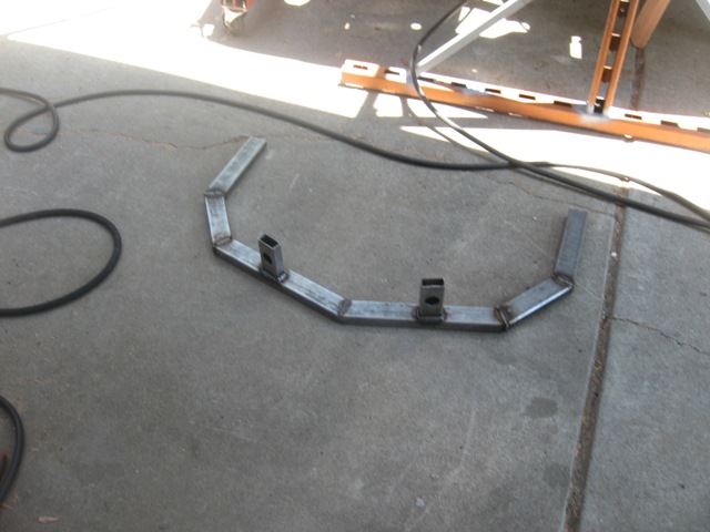 The cradle will bolt to mounting ears that I'll weld on gussets that I've installed on the upper longs (see below). I believe the cradle will help tie together the rearward portions of the longs, and the gussets that I've fabricated will tie in the lower portion of the GT kit and the inner potion of the longs. Below are a couple pictures of the gussets that I fabricated out of 16 ga. steel -- prior to welding and then after rosette welds / grinding smooth. 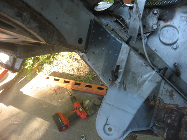 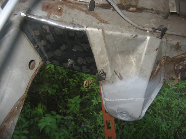 Here is the clearance and mock-up of the transaxle:  Finally, here is a pic of the engine bay, showing where the turbo will be mounted. Obviously, I need to cut out a portion of the rear firewall/trunk floor, and construct a box for the turbo. I also need to box in clearance for the hydraulically-controlled clutch and possibly the starter. With regard to the starter, I'm still investigating the gear-reduction WRX starter, which is "clocked" such that it might fit under the stock rear firewall. More to come on that. 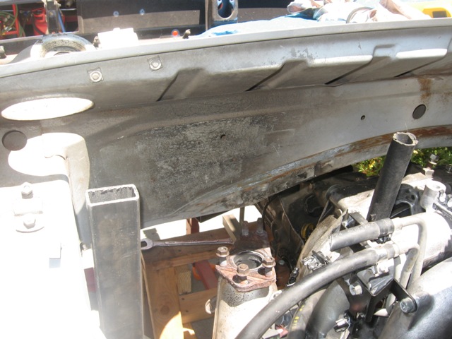 Next up is completing the seam welding of the driver-side gusset, fabricating/welding the passenger side long gusset, completion of the mounting ears for long-to-cradle, and completion of the cradle. Then I'll fabricate the transaxle mount. I hope to tie the cradle to the transaxle mount to keep the tail of my teener connected to middle of the car. In terms of fore-aft location of the engine/trans, I tried to keep the engine located as far back as possible to keep a slight rearward weight bias and to line up the output flange-to-hubs to the extent possible. According to my measurements, the angle is ~0.50" off (output flange is slightly forward of the hub) -- which is less than the angle of the stock Subaru output-to-hub setup (~1.0" offset). Stay tuned... |
   |

 
|
| strawman |
Aug 24 2009, 01:43 PM
Post
#82
|
|
Senior Member Group: Members Posts: 881 Joined: 25-January 08 From: Los Osos, CA Member No.: 8,624 Region Association: Central California |
I haven't posted in a while, but I've been busy.
I completed the engine mount system, as well as the transmission mount system. My wife-n-daughter were away this weekend and they took the digital camera, so I was unable to take any pics of my recent progress. I'll snap some shots in the coming days and post them here. But the big news is that I sold my racing karts on Sunday to bring some more money to the project. I just ordered an OBX planetary limited slip for my Suby trans. I'll try to chronicle that build soon after the unit arrives. I also just got off the phone with Chuck at Elephant Racing Products and bought the following items: 1. Polybronze suspension bushings, front and rear 2. Tarett front sway bar and weld-on A-arm mounts 3. Front monoball camber plates 4. Balljoint mount kits. I plan to drive down to San Jose next week to pick up the items, and to have him check out my Bilstein Sport strut inserts. Elephant now rebuilds & revalves Bilstein struts ($250/pair; Bilstein in Poway only charges $150/pair). I plan on staying with the stock 911 18.8mm torsion bars up front for now, although he is suggesting that the Bilstein Sports are "too much" for the stock front 911 torsions -- especially in a 914. I'm a little reluctant to move up to a larger set of front torsions until I have a chance to drive the car. Anyone have some advice for me, both in terms of the torsion bars and strut inserts (I have 911 Bilstein strut housings)? Maybe it would be best to finish assembling the car, corner weight it and then send the strut inserts in for a rebuild/revalve? The car will be used primarily for spirited mountain road driving, occasional autocrosses and some HPDE track events. Geoff |
|
|
|
| strawman |
Sep 3 2009, 10:56 PM
Post
#83
|
|
Senior Member Group: Members Posts: 881 Joined: 25-January 08 From: Los Osos, CA Member No.: 8,624 Region Association: Central California |
Here are some pics of the suspension stuff I picked up from Elephant Racing Products yesterday. Chuck is a really nice and knowledgeable guy, and I had fun looking around his shop in Santa Clara. Like many hot rod shops, it is pretty unassuming from the outside, and I drove by it twice looking for a great big neon sign...
I also ordered some Bilstein (pronounced Bil-Stine, I now know) rear shocks, front Bilstein linear bushings, and front strut wiper seals that ERP will ship in the coming days. 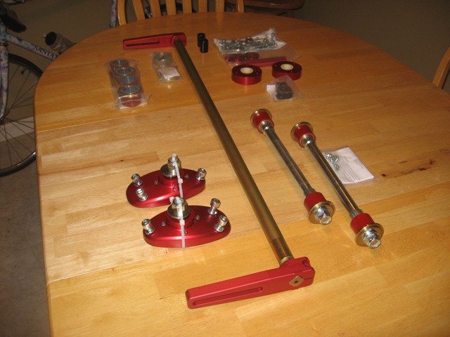 Besides the stuff listed in the post above, I also bought new bearing seats for my Bilstein strut housings. I already have new wheel bearings and seals for when I put the front end back together. This weekend I plan to weld in stiffening tubes in the spare trailing arms I have, similar to Eric Shea's modifications (the wrap-around stiffening kits really make the arms really HEAVY, I've found!). I also plan to weld on the rear trailing arm e-brake pivots, raise the spindles 19mm on the front Bilstein strut housings, weld on the A-arm sway bar mounts, sandblast all suspension pieces, and I hope to find time to take the lot to a powder coating firm in Sacramento next week. Time permitting, I'll also tear into the Suby trans this weekend to install the OBX limited slip. I'll take pics as I go for anyone interested in the guts of these boxes. I've never been inside this box before, but I've had experience setting up ring-n-pinions when I was into four-wheeling so I'm not too escairt. Below is a pic of the Suby trans mount, as bolted to the stock 914 location using 911 engine mounts. I've also attached a pic of the trans mount bolted on the Suby trans. This mount will provide a nice "canvas" for mounting the cable shifting system... 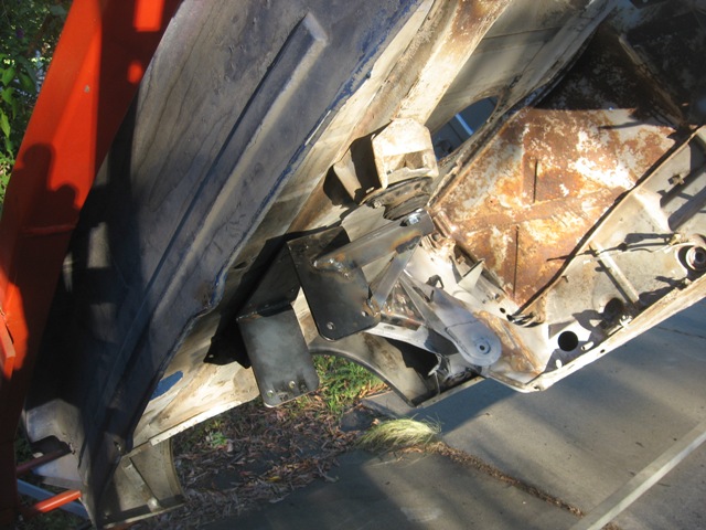 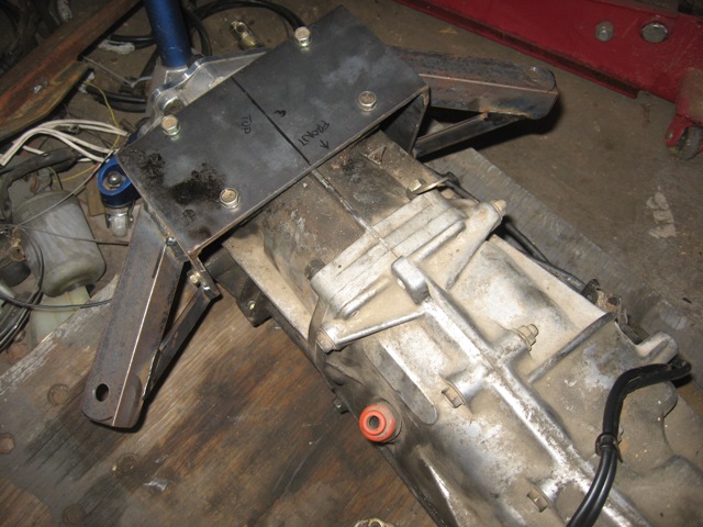 |
|
|
|
| strawman |
Sep 12 2009, 10:44 PM
Post
#84
|
|
Senior Member Group: Members Posts: 881 Joined: 25-January 08 From: Los Osos, CA Member No.: 8,624 Region Association: Central California |
A little update...
I welded on the front sway bar tabs on the A-arms, removed the ball joints, burned out the factory rubber bushings and sandblasted the arms. I hope to get them to the powdercoater this week so that I can install the new hardware depicted in an earlier post. No pics, as this isn't exactly rocket science. Below is a pic of the raised spindles on my 911 Bilstein struts. After searching the Pelican site and a few Porsche mod shop websites, I decided to raise the spindles a total of 30mm (instead of 19mm as indicated in an earlier post). It took a lot of time grinding out the factory rosette weld, measure depth, grind more and measure again until I was sure I ground out enough without bunging up the strut tube. Even still, it stressed the 55-ton press I have access to pop it free and keep it moving to the desired height. 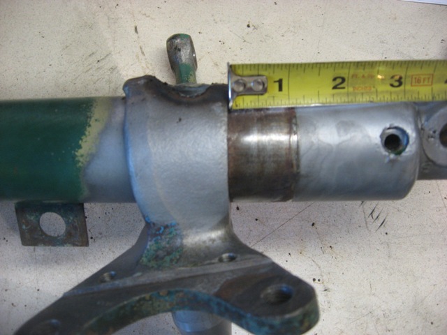 I plan to weld on a lower "arm" onto the strut tube just above the ball joint roll-pin hole so that I can run a long bolt between the factory arm (drilled out to 14mm) and this new arm, with spacers to get the optimal tie-rod height to reduce bumpsteer. Stay tuned for pics of that completed mod as soon as I procure suitable bolts and spin spacers on the lathe in the coming weeks. The rear Bilstein dampers arrived this week, but no pics are necessary. I also tore apart the Suby trans, and everything looks good (it shifted fine when removed). Even so, I ordered new bearings throughout and plan to assemble it this week with the OBX limited slip. Stay tuned for pics of that, too. |
|
|
|
| strawman |
Sep 12 2009, 11:08 PM
Post
#85
|
|
Senior Member Group: Members Posts: 881 Joined: 25-January 08 From: Los Osos, CA Member No.: 8,624 Region Association: Central California |
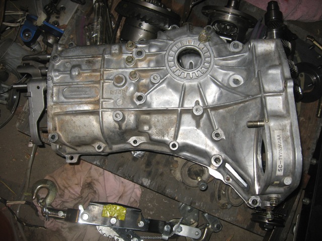
Okay, so I just got another cocktail, and thought I'd take the time to add some more details of the trans teardown.
First up is a pic of the trans on my workbench, with the rear and mid case removed. As noted, you can see the Bremar coupler. You can also see one of the two trans side covers that provide the side-side adjustment of the differential/ring gear to get a good pinion / ring gear pattern. 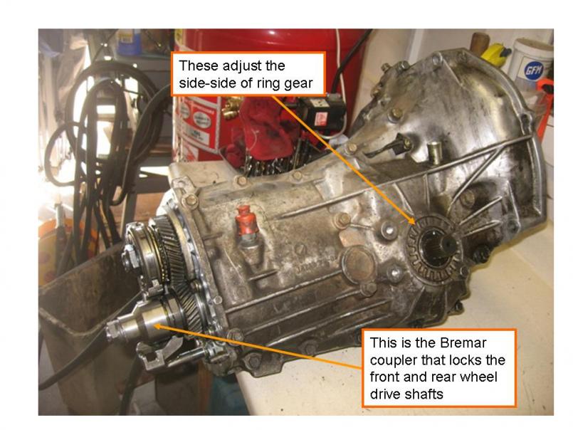 Here is a pic of the mid case draining out the nasty-smelling gear oil. As part of the Bremar FWD conversion, you toss the rear case & guts, which originally housed the center differential. The shift rod is also shown in this pic. 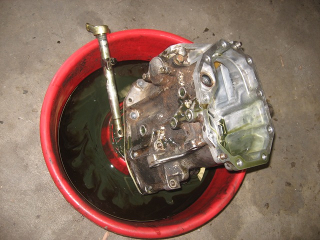 Next is a pic of the guts of the trans. 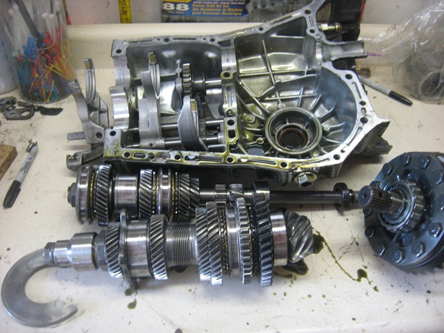 Here is a side-by-side of the factory diff and the OBX limited slip. 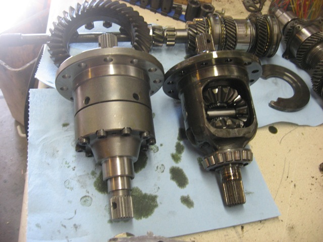 |
|
|
|
| strawman |
Sep 12 2009, 11:12 PM
Post
#86
|
|
Senior Member Group: Members Posts: 881 Joined: 25-January 08 From: Los Osos, CA Member No.: 8,624 Region Association: Central California |
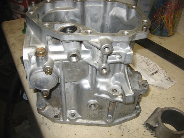
And here are a couple of pics of the main and mid trans cases all cleaned up. Just waiting for the new seals, o-rings and bearings that will hopefully arrive this week.
  |
|
|
|
| charliew |
Sep 17 2009, 11:14 PM
Post
#87
|
|
Advanced Member Group: Members Posts: 2,363 Joined: 31-July 07 From: Crawford, TX. Member No.: 7,958 |
I like the engine cradle it's similiar to Tony's. Looks good.
Are you going to expect the pinion depth to remain the same after you replace the bearings on the pinion shaft? Did you happen to check the backlash on the original setup? Just curious as I am going to put 05 legacy internals in a 02 wrx case with the obx and I saw where suby has a flat plate tool to set pinion depth. It looks like one could be made using a known good setup and using it on later rebuilds. It uses two pins that register in the case bolts and butts against the end of the pinion it seems from pictures I've seen. Since you are not changing the ring and pinion you might be ok just setting the backlash as that seems to be your game plan. Thats seems to be what the guys on nasioc are doing. I guess thats the early tranny from the 93 instead of the 99 tranny you mentioned at the first? It looks like the tt one I have. Is it a 4:11 or 4:44 fd? I read somewhere that the pre 99 tranny were different but the 96 I have looks a lot like the 02 wrx and the 05 legacy other than the clutch arm and the axle stubs missing on the 05 and the removable plate on top of the center case of the early tranny. While you are in there look how much room there is with the center diff out. I'm thinking the cables for the shifter could be internal and that would clean up the rear of the car under the bottom. |
|
|
|
| strawman |
Sep 18 2009, 07:33 PM
Post
#88
|
|
Senior Member Group: Members Posts: 881 Joined: 25-January 08 From: Los Osos, CA Member No.: 8,624 Region Association: Central California |
QUOTE(charliew @ Sep 17 2009, 10:14 PM)  <snip> ... Since you are not changing the ring and pinion you might be ok just setting the backlash as that seems to be your game plan. Thats seems to be what the guys on nasioc are doing. Hi Charlie, Yup, I'm only planning to set the backlash and test to make sure I've got a good gear pattern. QUOTE(charliew @ Sep 17 2009, 10:14 PM) I guess thats the early tranny from the 93 instead of the 99 tranny you mentioned at the first? It looks like the tt one I have. Is it a 4:11 or 4:44 fd? I read somewhere that the pre 99 tranny were different but the 96 I have looks a lot like the 02 wrx and the 05 legacy other than the clutch arm and the axle stubs missing on the 05 and the removable plate on top of the center case of the early tranny. No, I've confirmed from the part number that it is out of a 1998 Forester, with the 4.11 ratio. It has a transmission code of TY753VJ1AA. QUOTE(charliew @ Sep 17 2009, 10:14 PM) While you are in there look how much room there is with the center diff out. I'm thinking the cables for the shifter could be internal and that would clean up the rear of the car under the bottom. I'm not sure that would be possible; where would the cables enter the case? And how would you rotate the rod with the cables inside the case? I think cable shifting at the back of the trans should be fine... Geoff |
|
|
|
| strawman |
Sep 21 2009, 02:16 PM
Post
#89
|
|
Senior Member Group: Members Posts: 881 Joined: 25-January 08 From: Los Osos, CA Member No.: 8,624 Region Association: Central California |
QUOTE(charliew @ Sep 17 2009, 10:14 PM) Are you going to expect the pinion depth to remain the same after you replace the bearings on the pinion shaft? Hi Charlie -- I neglected to state in my previous posting that I am not replacing the bearings on the pinion shaft -- only those of the mainshaft and differential bearings. Finished up the trans reassembly this weekend, and began mocking up the cable shifter setup. I'll try to post pics later today or tomorrow. Geoff |
|
|
|
| charliew |
Sep 22 2009, 07:54 AM
Post
#90
|
|
Advanced Member Group: Members Posts: 2,363 Joined: 31-July 07 From: Crawford, TX. Member No.: 7,958 |
I'm sorry Geoff, by early I meant the 99 and earlier trannys, I think they are the only ones with the inspection cover on top of the gear case.
The 4:11 should give a little relief to the gears regarding the torque applied to them. Also it will have a pretty short low, I'm anxious to see how you like it. I really think the 3:90 is probably the best unless a 3:54 is available because the car is so light, but tire dia could also be used to adjust the fd some be. Of course that puts much more strain on the gears and shafts. The rotational motion would be the same inside the case as the outside but might require more leverage at the shifter as the internal arm inside the case would need to be so short. The cables would need to enter higher than the fluid level, I would think. |
|
|
|
| strawman |
Sep 23 2009, 11:12 PM
Post
#91
|
|
Senior Member Group: Members Posts: 881 Joined: 25-January 08 From: Los Osos, CA Member No.: 8,624 Region Association: Central California |
So I finished up the installation of the OBX limited slip differential, including many new bearings (mainshaft and diff bearings) and all new seals/o-rings. The LSD was $412 delivered, and the bearings/seals was another $200.
First pic is of the guts, including the anaerobic gasket maker. 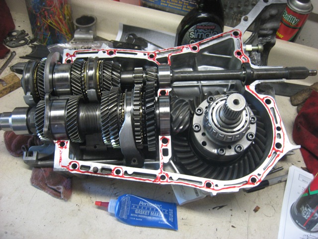 Next up is a pic of the main case halves bolted and torqued, as well as the "mid" case bolted and torqued. Note that the "rear" case is eliminated with the Bremar 2wd kit... 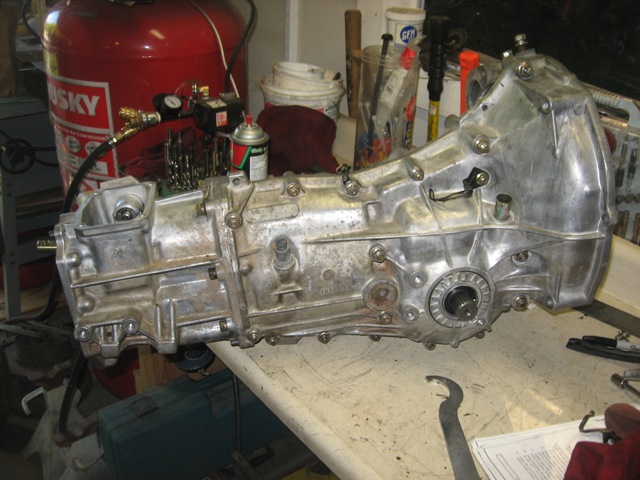 I then bolted up the trans to an engine stand to begin setting the backlash. As you can see in the photo below, you need to weight the differential (in this case, that is a 911 front brake rotor wired to the driver-side axle stub). This essentially pulls the ring gear away from the pinion gear. Note that I didn't replace the pinion bearings, because they looked to be in great shape and I didn't want to mess with the pinion depth... hopefully that decision won't end up biting me in the ass. The passenger side adjuster is installed without its o-ring so that you can easily turn that side's adjuster. 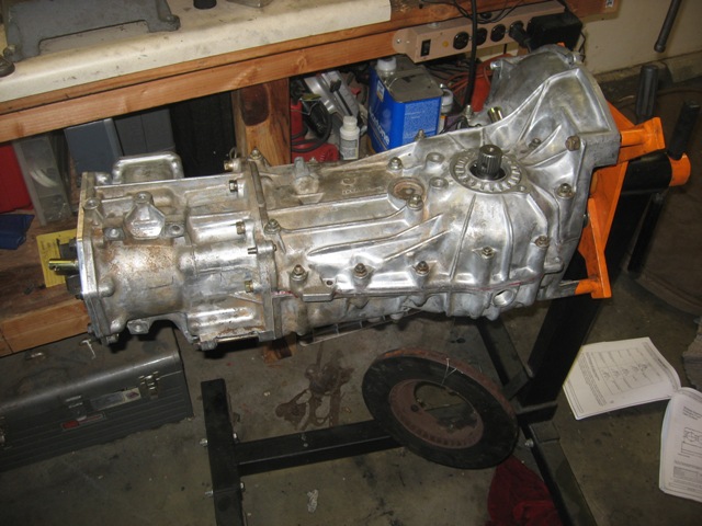 You then screw in the driver side adjuster from below until you make contact between the ring gear and the pinion gear. Then you adjust the passenger side in until you preload the case bearings. Next you back off the driver side 1.5 notches (see the "teeth" on the adjuster?), temporarily tighten the passenger side adjuster 1.5 notches, mark that location, back off the passenger side adjuster enough to install the o-ring, and then tighten the passenger side back to its marked spot. Finally, you secure the adjusters using the locks (I didn't take a pic of those, but they're bolted in the threaded hole that is slightly obscured by the bicycle lock-ring tool in the pic below. 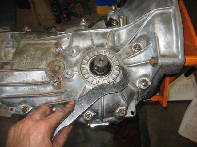 |
|
|
|
| strawman |
Sep 23 2009, 11:32 PM
Post
#92
|
|
Senior Member Group: Members Posts: 881 Joined: 25-January 08 From: Los Osos, CA Member No.: 8,624 Region Association: Central California |
Now that the transmission is ready to go, I started on the mock up of the shifter and cables. I am using an AW11 model Toyota MR2 ('85 to '89) shifter that I picked up at a local Pick-n-Pull for ~$25, including the shifter cables. Here is a pic of the shifter on a module that I welded up and bolted to the top of the transmission.
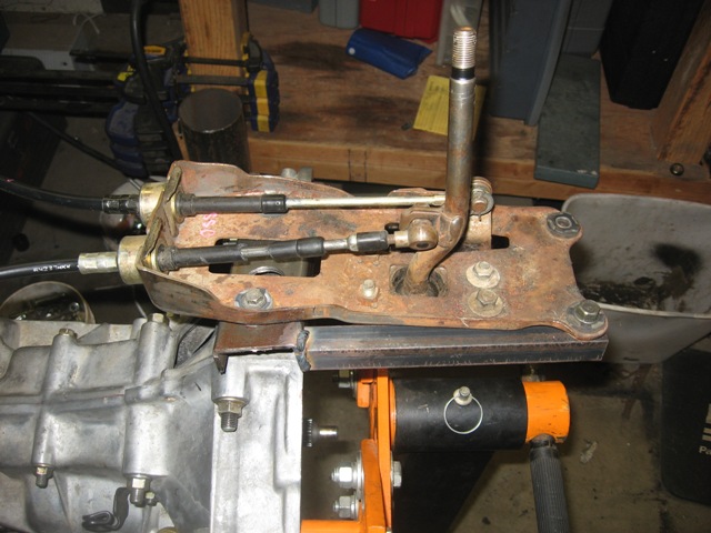 Next up are a couple of pics of the business end of the shifting mechanism. Obviously this is a mickey-mouse mock-up -- but I wanted to see how tall the shifter upright needed to be, and where to locate the left-right stand-off. I clamped the upright to the shift-rod connector using Vise-Grips until I got the height of the upright correct, then tack-welded it. It shifts great, despite the extreme angle of the fore-aft cable. Custom cables will take out the these kinks... 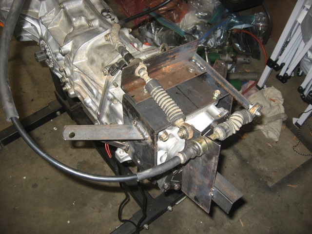 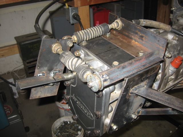 It should be noted that the movement of the shift rod fore-aft and side-side is very acute. Below is a series of four pictures that depicts the side-side (note the rubber boot is scrunched when you compare the top two pics when moving the shifter from the 1-2 gate to the 5-R gate) and fore-aft (note the differing distances of the upright in comparison to the rear of the trans when the shifter is moved from 1st to 2nd). 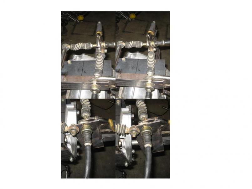 I'll make the whole mechanism much more pretty, and weld the stand-off to the trans-to-body mount. I'll probably have to make up a new module for the shifter, too so that I can accommodate the length of the cables, which will use rod ends at each end. Stay tuned! |
|
|
|
| strawman |
Oct 22 2009, 01:12 AM
Post
#93
|
|
Senior Member Group: Members Posts: 881 Joined: 25-January 08 From: Los Osos, CA Member No.: 8,624 Region Association: Central California |
I finally got around to finishing the rear trunk replacement, including cleaning up the welds, ospho-ing the bare metal, and epoxy primering those prepped areas. While I had the spray gun out, I also epoxy primered the GT chassis kit, the passenger side suspension console, the Tangerine Racing suspension ear reinforcements and the engine mounts. Finally, I sandblasted the front 911 A-arms and epoxy primered 'em. I will take pics and post them this weekend.
I also finished up the raised spindles on the Bilstein struts that I showed in post #84 above. Below is a pic of the lower arm I fabricated and welded on. I made the concave cuts by simply using a 2" hole saw in the middle of a 2-foot piece of 2"x0.1875" flat bar stock; with a little massaging with a rat-tail file, the lower arms fit just about perfectly on the OD of the Bilstein strut housing at the correct angle. I cut a piece of 3/4" black gas pipe on the lathe to ensure it was cut square (2.5" long), and used that as a spacer while I welded the lower arm on each strut housing. I then drilled out the 14mm hole in the lower arm. It fits perfectly and square at the correct angle. I tapered the lower arms toward the rod end so it looks all purty. 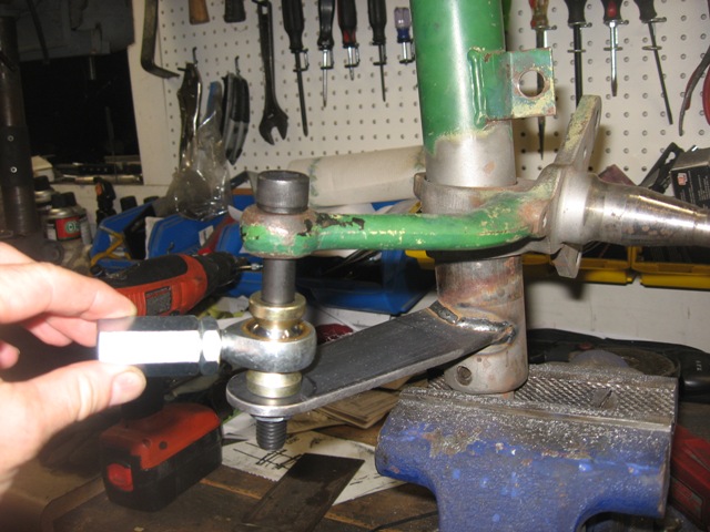 Getting the parts was a PITA, as I had to source stuff from both sides of the pond. I got the 110mm long M14 grade 12.9 Allen bolts from Grainger, as well as the 14mm drill bit. The 14mm female couplers (that mate the male rod end with the turbo tie rods setup) and some M14 castle nuts were sourced from specialty bolt supplier in SoCal. The rod ends, high-angle rod end spacers and jam nuts came from McGill Motorsports in England. I also sourced some cool rubber boots (not shown) that keep grime out of the rod ends from McGill. I still need to drill cotter pin holes in the bottom of the Allen bolts, chuck up some round stock to make the final spacers (after I mock up the front end and see where vertically the rod end should sit to avoid bump-steer), and then the hardware side of things should be wrapped up for steering setup. |
|
|
|
| JazonJJordan |
Oct 22 2009, 10:20 AM
Post
#94
|
|
Member Group: Members Posts: 340 Joined: 6-June 09 From: Atlanta-Augusta, Georgia area Member No.: 10,446 Region Association: South East States |
Awesome work and rustoration! Thanks for documenting it well.
Keep it up! (IMG:style_emoticons/default/laugh.gif) -Jordan |
|
|
|
| Justinp71 |
Oct 22 2009, 10:30 AM
Post
#95
|
|
Senior Member Group: Members Posts: 1,583 Joined: 11-October 04 From: Sacramento, CA Member No.: 2,922 Region Association: None |
Looking good!
|
|
|
|
| charliew |
Oct 22 2009, 11:48 AM
Post
#96
|
|
Advanced Member Group: Members Posts: 2,363 Joined: 31-July 07 From: Crawford, TX. Member No.: 7,958 |
Geoff great pictures, I guess you decided 1.5 notches on the side to side clearance of the diff was a good backlash adj? If that is good it seems easy enough. It will be easy enough to turn in the driver side on the stock setup before I take it apart to see what it is before I take it apart. that way it will bo back the same. The only prob I will see that might change things is I want to put all 05 legacy stuff along with the obx inside a 96 or 02 wrx tranny that I have. The front to rear position of the pinion might be different. In order to use the 05 legacy gears I will also have to use the 05 shafts. The 05 legacy tranny I have has a busted case. I didn't get how you measured side to side bearing load on the diif though.
|
|
|
|
| strawman |
Oct 22 2009, 12:04 PM
Post
#97
|
|
Senior Member Group: Members Posts: 881 Joined: 25-January 08 From: Los Osos, CA Member No.: 8,624 Region Association: Central California |
QUOTE(charliew @ Oct 22 2009, 10:48 AM) ... I didn't get how you measured side to side bearing load on the diif though. Hi Charlie, I simply followed the Suby manual instructions to set the side-side bearing load. PM me with your email, and I'll send a copy to you. Geoff |
|
|
|
| strawman |
Oct 24 2009, 12:35 AM
Post
#98
|
|
Senior Member Group: Members Posts: 881 Joined: 25-January 08 From: Los Osos, CA Member No.: 8,624 Region Association: Central California |
Finally took some pics of my modified trailing arms (with the lateral tube stiffeners that I welded in a couple of weeks ago), along with a 911 e-brake setup. My e-brake setup is a flagrant plagiarism of Paul Seyegh's setup (you can actually see the Excellence Magazine article in the background of the pictures!!!). Thanks Paul...
The first pic is of the arms, with the relocated e-brake cable mounts and the pivots -- one hooked up, and the other laid out to see the various components. With regard to the latter, I used a 3/8" I.D. bronze shouldered bushing and flat 3/8" bronze bushing, along with a 1/2" I.D. collar welded to a bent piece of 3/16" hot-rolled steel stock. I figure I can use the set-screw hole to inject grease, and use the set-screw in the collar to keep it lubed and to keep out gunk. The bronze bushings should allow an easy/unfettered pivot; the Grade-8 3/8" flanged bolt welded to the trailing arm should provide ample strength. 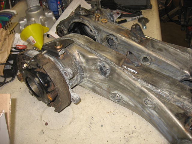 The second pic is a close-up of the various components of the pivot. The black Sharpie line depicts where the pivot will sit when the parking brake handle is released. Obviously, I haven't yet drilled a hole for the e-brake cable hook-up yet in the pivot in this pic. 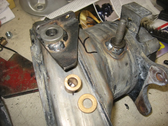 The final pic shows the e-brake cable hooked up, along with a 1/4" x 2.5" SS Allen bolt hooking up the pivot to the e-brake expander. 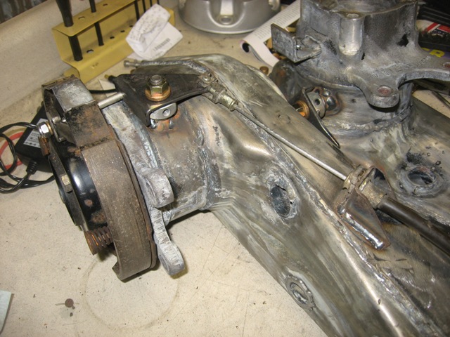 I hope to sandblast the arms and other various components tomorrow, and to epoxy primer everything. I bought some urethane semi-gloss black paint this week, and I hope to also paint all my epoxy primered suspension components tomorrow. I'm gonna forego the Bilstein green on the front struts... I like the idea of black against orange (green and orange would be too "pumpkin" for my liking). |
|
|
|
| DBCooper |
Oct 24 2009, 05:49 AM
Post
#99
|
|
14's in the 13's with ATTITUDE Group: Members Posts: 3,079 Joined: 25-August 04 From: Dazed and Confused Member No.: 2,618 Region Association: Northern California |
Extremely well done. You're knocking out things that I've been planning forever to get around to.
|
|
|
|
| al weidman |
Oct 30 2009, 11:55 PM
Post
#100
|
|
Al Weidman Group: Members Posts: 156 Joined: 22-February 08 From: Oroville, Ca. Member No.: 8,736 Region Association: Northern California |
Geoff, just reviewed the thread so I can remember all you have done and remember to look at. My brother, Harvey will be with me, we will try to be there 2:30 to 3:00. Hasta manana, Al. (IMG:style_emoticons/default/driving.gif)
|
|
|
|
|
1 User(s) are reading this topic (1 Guests and 0 Anonymous Users)
0 Members:

|
Lo-Fi Version | Time is now: 12th May 2024 - 12:40 PM |
Invision Power Board
v9.1.4 © 2024 IPS, Inc.