|
|
|
Porsche, and the Porsche crest are registered trademarks of Dr. Ing. h.c. F. Porsche AG.
This site is not affiliated with Porsche in any way. Its only purpose is to provide an online forum for car enthusiasts. All other trademarks are property of their respective owners. |
|
|

  |

| brer |
 May 24 2008, 02:41 PM May 24 2008, 02:41 PM
Post
#21
|
|
Advanced Member  Group: Members Posts: 2,555 Joined: 10-March 05 From: san diego Member No.: 3,736 Region Association: None |
are those Lobro CV's you are using?
if they are the Empi ones then you will break them. a known fact in dune buggy circles. some get less than an hours use before failure. |
   |

 
|
| davep |
May 24 2008, 02:54 PM
Post
#22
|
|
914 Historian Group: Benefactors Posts: 5,290 Joined: 13-October 03 From: Burford, ON, N0E 1A0 Member No.: 1,244 Region Association: Canada |
Is there any wheel hopping on the course? Something that would put high instantaneous loads on the CV? I wonder if the cryo process would have any benefit? The metallurgy of the parts may have some part in the failure.
|
|
|
|
| yarin |
May 24 2008, 03:26 PM
Post
#23
|
|
'14-X'in FOOL Group: Members Posts: 988 Joined: 13-May 03 From: Guttenberg, NJ Member No.: 693 Region Association: North East States |
QUOTE(davep @ May 24 2008, 04:54 PM)  Is there any wheel hopping on the course? Something that would put high instantaneous loads on the CV? I wonder if the cryo process would have any benefit? The metallurgy of the parts may have some part in the failure. There is really no aggrevated "hopping" as in aggressive wheel spin on launching. However, the when a corner unload on the throttle that wheel will spin a little and catch upon settling the weight distribution. I was discussing heat treating the parts before installation with a few engineers, beneficial?? |
|
|
|
| Eric_Shea |
May 24 2008, 03:37 PM
Post
#24
|
|
PMB Performance Group: Admin Posts: 19,304 Joined: 3-September 03 From: Salt Lake City, UT Member No.: 1,110 Region Association: Rocky Mountains |
Those are German "Meyle" not EMPI. We compared the Meyle and the Lobro side by side in the first few batches and didn't see any differences.
I would think that cryo might help and there's a guy in your neck of the woods (Mass) that does it. Can't think of where they are but the guys name is Robin if I recall and very nice guy to work with. |
|
|
|
| brer |
May 24 2008, 04:00 PM
Post
#25
|
|
Advanced Member Group: Members Posts: 2,555 Joined: 10-March 05 From: san diego Member No.: 3,736 Region Association: None |
Meyle is a German company that does not produce their parts there any longer.
Its better than Empi, but it is still an aftermarket part. Made in Turkey and beyond. I've used their parts on my Benz and the difference in quality is immediately apparent from OEM. They worked well, but still aftermarket. I'm not knocking your work Eric and definitely keep offering them for sure! not like there are other options for our cars. (IMG:style_emoticons/default/sad.gif) I would Install a German Lobro and see how she goes. |
|
|
|
| Eric_Shea |
May 24 2008, 05:20 PM
Post
#26
|
|
PMB Performance Group: Admin Posts: 19,304 Joined: 3-September 03 From: Salt Lake City, UT Member No.: 1,110 Region Association: Rocky Mountains |
I can switch to Lobro no problem if that's deemed the problem but with 2 failures in almost 2 years, I'm not altogether sure there "is" a problem.
Lobro would be about $15-20.00 more. |
|
|
|
| Jeff Hail |
May 25 2008, 12:59 AM
Post
#27
|
|
Senior Member Group: Members Posts: 1,141 Joined: 3-May 07 From: LA/ CA Member No.: 7,712 |
QUOTE(Eric_Shea @ May 24 2008, 10:29 AM) QUOTE P.S. Silence Jeff! Back to that welding thing you do... now! (IMG:style_emoticons/default/tongue.gif) Eric, I have been.... and priming,powdercoating and painting suspension parts. All sorts of good stuff! Better living thru chemicals! I will chime in anyways as I have exposure to CV failure in a broad area. Lots a racing background earlier in life. Have seen my share of axle blow ups over and over again. The stock 914 CV is fine for a stock car with normal day to day driving loads as it was designed. An acceptable failure percentage is all part of the equation in mass produced parts. If 2% or even 5% failed that is usually acceptable to the manufacturer. That’s why new cars have warranties! Many years ago I was working with some Formula Fords and Vee cars. Nothing special. No high horsepower just really light cars that were capable or very high loads for what they were. I have also worked with high HP 911 based race cars and those loads increase exponentially. CV's, Guibos, Tripod joints are all amazing mechanically. They do two things. They allow radial and axial mis-alignment to transmitted rotational energy. Easy enough to comprehend. We can all visualize how it works. Now the complicated part. The design of a CV joint can only contain so much radial stress subject to torque. Radial stress is stress towards or away from the central axis of a curved member (this would be the double ball design of a CV joint) For each axis (3 on a 914 CV) we have 2 balls positioned in a V pattern. One right and one left. Without the double ball V pattern creating equalization the joint would unscrew itself to death. The forces on the outer housing are mechanically manageable. The weakness is the 4 bolt pattern. Roll pins will squish a bit and allow the outer housing to expand and twist even just 1/1000th of an inch! . Sometimes this will cause a failure..Sometimes not. Now we need to look at "Hoop stress". HS is mechanical stress defined for rotationally-symmetric objects being the result of forces acting circumferentially (perpendicular both to the axis and to the radius of the object). Along with axial stress and radial stress, it is a component of the stress tensor in cylindrical coordinates. I know everyone has lost me here. So get a beer and read on. The 914 CV housing is flame heat treated at the bearing contact area but not the entire housing. This is so the bearings don't wear away at the contact area. The rest (outer part) of the housing is not heat treated. This area remains "soft". With only 4 bolts holding everything together the area at the roll pins are outside the "rectangle of strength" are a weak point. No clamping pressure is present to contain the forces dead center between 3 balls radially around the circle . Now let’s look at the bearing cage. It's thin. If the machining of the cage is not an ideal spacing to the outer housing unequal forces get generated. I know, I know it’s just a CV joint but really look at it closer. If the cage does not match the outer housing precisely within its 360 degree circumference problems develop. If the ball bearings are not equal all the way around the joint unequal forces are exhibited. Measure your balls with a caliper! Centrifugal load forces become unequal at 3 points. With torque and rpm's something is going to give. This is usually the result of the bearing cage expanding beyond its elastic limits (ala cracks) and ultimate failure. Matching the cage to the outer housing and uniform bearings are paramount to durability as with any rotating assembly. Taken a step further. Smaller engines tend to have higher gear ratios. The lower gears are very high which get the vehicle "out of the hole" without to much effort but essentially shock the drive train in racing conditions. Even without big horsepower this still takes it toll on CV joints via wind up. The first 2 gears will have highest load on CV's. The wider the gear spacing the higher the "shift shock". High acceleration and continuous hard braking exaggerate this even more. A tight CV will behave differently than a loose CV. The closer the tolerance between housing, cage and balls will be more durable in the long run. Another issue is angle of misalignment. The higher the angle the more stress is placed on the CV joint axially. Add the range of suspension travel in a 914 to this. The higher the angle the higher incidence of failure will occur. Choices? Decrease suspension range of travel or increase CV joint strength for given range of motion. What can be done? I know by experience...You can hone and polish the outer housings to make everything slick & slippery! Any sharp edges can be radiused and polished. Equally done to the bearing cages. All your balls must be matched to the 1/1000th for racing! Failure rate will decrease or you can go with a more robust joint. Tripod joints have a much less rate of failure than standard CV's due to inherent design. A six bolt pattern versus a 4 bolt pattern equalizes housing forces better. A wider outer housing does wonders with an increase in torque. INTERMISSION: I have a big bag of Reese's Pieces I am tearing into. I am back. Being that I am going with late Carrera axles,hubs with spacers stock 914 is not so much of a concern for me. For others I maybe able to help. What is the bolt pattern for a stock 914 CV joint in inches or MM's, also I need the stock 914 axle spline #? The reason is Loebro and other suppliers have been making a 6 bolt racing CV for years that may be workable on the 914. An option is lightweight billet aluminum housings with replaceable steel cages for less than you would think. Ok Eric. I am going back to the welding thing I do now! |
|
|
|
| Joe Ricard |
May 25 2008, 07:32 AM
Post
#28
|
|
CUMONIWANNARACEU Group: Members Posts: 6,811 Joined: 5-January 03 From: Gautier, MS Member No.: 92 |
I think the materails being used these days are not what they used to be.
Not saying I put the most abuse on my but more then 700 autocross runs and 30,000 miles in 5 years. the joints that were in the car were old but lasted until the bigger motor was installed. I had loose joints so I replaced them with with old spares. these spares have been in the car for several years. Big slicks and driving the wheels off it. Like to give a shout out to Eric for being an upstanding guy. I think the good old joints are ging to be worth even more in the near future. |
|
|
|
| davep |
May 25 2008, 09:22 AM
Post
#29
|
|
914 Historian Group: Benefactors Posts: 5,290 Joined: 13-October 03 From: Burford, ON, N0E 1A0 Member No.: 1,244 Region Association: Canada |
Being a physicist, I can understand what Jeff is talking about. Hence my questions about suspension travel and hopping. It may be that Eric will have to offer two types of CV's. One for the street cars and another for the racers. I think an AXer will be harder on the CV vs the track guys.
Even a little slip and grab will be hard on the CV especially if the axle is at an angle. The Loebro may be well worth the extra $$ if it reduces the failure rate farther; say 4 years instead of 2 years use. More heat treatment or perhaps cryo treatment may also help extend life. Basically, the CV will always fail, it is a matter of time. It may be worth inspecting the cages for cracks on a regular basis, and replace them before they fail. I suspect the CV was failing (crack present) for a while before it broke. |
|
|
|
| Eric_Shea |
May 25 2008, 12:31 PM
Post
#30
|
|
PMB Performance Group: Admin Posts: 19,304 Joined: 3-September 03 From: Salt Lake City, UT Member No.: 1,110 Region Association: Rocky Mountains |
QUOTE Ok Eric. I am going back to the welding thing I do now! Alright, alright... so you know everything! (anybody else hate this guy? Welds like he does, knows all this $hit, has all the cool tools... can devour entire bags of Reeses Pieces in a single bound (IMG:style_emoticons/default/dry.gif) ) You should write a book... (IMG:style_emoticons/default/biggrin.gif) Seriously, thanks Jeff. That's about as good-a-info we've gotten so far. What I got, plugging in Yarins autocrossing as the general use, is: QUOTE The first 2 gears will have highest load on CV's. Not too many autocross courses that get beyond those two gears. Thanks Joe... I'm wondering (goofy thought); could it be the older CV's that Joe put in have "polished themselves" a bit through the wear cycle of normal use? (IMG:style_emoticons/default/confused24.gif) |
|
|
|
| yarin |
May 25 2008, 12:41 PM
Post
#31
|
|
'14-X'in FOOL Group: Members Posts: 988 Joined: 13-May 03 From: Guttenberg, NJ Member No.: 693 Region Association: North East States |
Thanks for all the info guys! Joe has put way more autox time and street miles on this stock CVs than I have without any issues. He is also running MUCH more rubber and stickier rubber. The sample size of this experiment is too small, not controlled and has too many variables to come to any real conclusion. I'll put the new joint through its paces and see what happens, odds are you probably won't hear from me for a few years...
Hands down, Eric is one of the best vendors I've ever dealt with. Thanks!! Side question - What's the best method of installing the inner race on the splined shaft? I'd prefer to install it without removing the other CV from the hub, but i doubt that is possible without inducing excess movement into the other CV. So, once removed, what technique do you guys recommend? It's a bitch to get on and off. Some sort of large press with pads? |
|
|
|
| Katmanken |
May 25 2008, 02:43 PM
Post
#32
|
|
You haven't seen me if anybody asks... Group: Members Posts: 4,738 Joined: 14-June 03 From: USA Member No.: 819 Region Association: Upper MidWest |
Eric,
CV joints are a lot like ball and roller bearings, they don't manufacture them rough and expect them to polish themselves. Like bearings, it's a finely balanced mix of tight tolerances, near perfect machining, really round balls, surface finish, and hardened surfaces.... Ken |
|
|
|
| Eric_Shea |
May 25 2008, 02:49 PM
Post
#33
|
|
PMB Performance Group: Admin Posts: 19,304 Joined: 3-September 03 From: Salt Lake City, UT Member No.: 1,110 Region Association: Rocky Mountains |
QUOTE they don't manufacture them rough and expect them to polish themselves. (IMG:style_emoticons/default/blink.gif) Thanks Ken... I was just going off Jeff comments: QUOTE What can be done? I know by experience...You can hone and polish the outer housings to make everything slick & slippery! Any sharp edges can be radiused and polished. Equally done to the bearing cages. All your balls must be matched to the 1/1000th for racing! My line of thinking was years of use may have caused some micro polishing... Back to being a dummy now. |
|
|
|
| Jeff Hail |
May 25 2008, 04:38 PM
Post
#34
|
|
Senior Member Group: Members Posts: 1,141 Joined: 3-May 07 From: LA/ CA Member No.: 7,712 |
QUOTE(Eric_Shea @ May 25 2008, 11:31 AM) QUOTE Ok Eric. I am going back to the welding thing I do now! (anybody else hate this guy?) One more thing. The 914's sheetmetal suspension ears are very prone to lateral movement under cornering loads. If the ears are allowed to teater in and out on side load the entire axle assembly will follow. What does this mean? Axle moves in and out. High range of misalignment is designed into the CV assembly although the cage itself does not allow for that much lateral play. The result may be the ball trying to escape its confinement and popping the cage apart. So why did it pop? Erics your analysis on the prior page shows a good eye for the wear found on the inner race. The cage showed very little contact wear at the cracked area. This can be from a lowered car on the bump stops while corning. Throw in some lateral movement on the trailing arm and kaboom. I do also see two burrs, one on the outer housing to the point where the edge is rolled. The other is on the inner cage at the crack. Notice is right between the bearing reliefs on both parts? Need to figure out primary cause and secondary damage from the failure. I tend to sway towards trailing arm moving in and out under load. More so as it was the inner CV that went away. To help understand the dynamics of a CV in action the first picture shows all parts at rest in a straight line. No stress's. Doesnt really matter whether is an inner or outer CV as the dynamics are the same. The second pic shows an exaggerated angle of attack for the axle shaft and inner race in relation to the cage and outer housing. This would apply to a lowered car. If excessive lateral movement of the outer housing occurs (trailing arm goes in/out on cornering/ acceleration load) the cage will pop. Attached image(s) 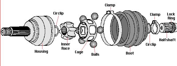 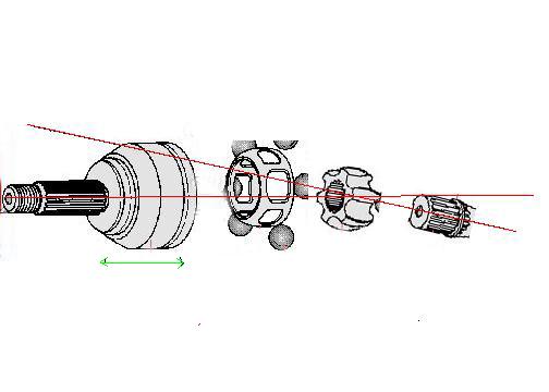 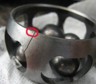 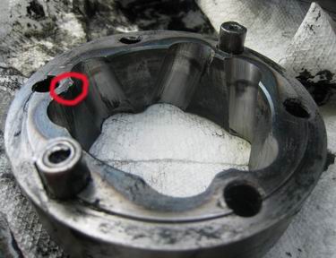
|
|
|
|
| yarin |
May 25 2008, 05:59 PM
Post
#35
|
|
'14-X'in FOOL Group: Members Posts: 988 Joined: 13-May 03 From: Guttenberg, NJ Member No.: 693 Region Association: North East States |
Hey Jeff, thanks for your in depth analysis.. but also don't forget the CV rolled for 50 miles after it failed and likely experienced significant rotational wear due to the cage failure. I would say it would be difficult to extract the root cause of the failure in this situation because additional damage/wear caused by towing after destruction.
|
|
|
|
| Katmanken |
May 25 2008, 07:08 PM
Post
#36
|
|
You haven't seen me if anybody asks... Group: Members Posts: 4,738 Joined: 14-June 03 From: USA Member No.: 819 Region Association: Upper MidWest |
I don't hate Eric....
Anybody who does, is doing him wrong... Eric has stepped up to the plate and is offering us a bolt in replacement for NLA parts and I respect him for it... Personally, I like dialogue that identifies a problem, and a collective group of minds that figures out a problem and makes it go away. Here's a thought.... Hows the bushings in the trailing arm? Tight or loose? If the bushings have slop and yer really doging cones, you might get some inward movement of the ends of the trailing arms which causes inward movement of the axles and REALLY high CV loads. Think that could lead to a CV joint failure???? It makes sense for a 30 year old car to have more than one problem that surfaces at another part........ Gawd, I hope we don't have to do a DOE! So, what kind of bushings and how much slop is in the specific trailing arm???? Load the crap outta it sideways,and measure the deflection If yer really dodging, the inward deflection could be quite high..... Ken |
|
|
|
| ericread |
May 25 2008, 08:50 PM
Post
#37
|
|
The Viper Blue 914 Group: Members Posts: 2,177 Joined: 7-December 07 From: Irvine, CA (The OC) Member No.: 8,432 Region Association: Southern California |
QUOTE(Jeff Hail @ May 25 2008, 03:38 PM) QUOTE(Eric_Shea @ May 25 2008, 11:31 AM) QUOTE Ok Eric. I am going back to the welding thing I do now! (anybody else hate this guy?) One more thing. The 914's sheetmetal suspension ears are very prone to lateral movement under cornering loads. If the ears are allowed to teater in and out on side load the entire axle assembly will follow. What does this mean? Axle moves in and out. High range of misalignment is designed into the CV assembly although the cage itself does not allow for that much lateral play. The result may be the ball trying to escape its confinement and popping the cage apart. So why did it pop? Erics your analysis on the prior page shows a good eye for the wear found on the inner race. The cage showed very little contact wear at the cracked area. This can be from a lowered car on the bump stops while corning. Throw in some lateral movement on the trailing arm and kaboom. I do also see two burrs, one on the outer housing to the point where the edge is rolled. The other is on the inner cage at the crack. Notice is right between the bearing reliefs on both parts? Need to figure out primary cause and secondary damage from the failure. I tend to sway towards trailing arm moving in and out under load. More so as it was the inner CV that went away. To help understand the dynamics of a CV in action the first picture shows all parts at rest in a straight line. No stress's. Doesnt really matter whether is an inner or outer CV as the dynamics are the same. The second pic shows an exaggerated angle of attack for the axle shaft and inner race in relation to the cage and outer housing. This would apply to a lowered car. If excessive lateral movement of the outer housing occurs (trailing arm goes in/out on cornering/ acceleration load) the cage will pop. WOW! Welcome to CSI-Jeff Hail!!! (IMG:style_emoticons/default/smilie_pokal.gif) Until I read this I figured the Butler did it with a Candlestick in the Library... (IMG:style_emoticons/default/confused24.gif) |
|
|
|
| Eric_Shea |
May 25 2008, 09:11 PM
Post
#38
|
|
PMB Performance Group: Admin Posts: 19,304 Joined: 3-September 03 From: Salt Lake City, UT Member No.: 1,110 Region Association: Rocky Mountains |
QUOTE I don't hate Eric.... Anybody who does, is doing him wrong... Eric has stepped up to the plate and is offering us a bolt in replacement for NLA parts and I respect him for it... Personally, I like dialogue that identifies a problem, and a collective group of minds that figures out a problem and makes it go away. Thanks Ken (IMG:style_emoticons/default/wub.gif) But I think Jeff misplaced an endquote in the html, which led to the same in Eric Read's post. I fixed them. I was just taking a (IMG:style_emoticons/default/poke.gif) at Jeff cuase he's so damn smart and he welds like a Motha &^%$er. Make no mistake, he's madly in love with me (he may not know it yet but... thems is the facts). (IMG:style_emoticons/default/biggrin.gif) Thanks all. This has been some pretty good analysis for sure. Big thanks to Jeff. I don't know how you pick this stuff up. I'm still trying to figure out where the little bally looking thingy's go. (IMG:style_emoticons/default/w00t.gif) |
|
|
|
| yarin |
May 25 2008, 10:41 PM
Post
#39
|
|
'14-X'in FOOL Group: Members Posts: 988 Joined: 13-May 03 From: Guttenberg, NJ Member No.: 693 Region Association: North East States |
All great points once again! How can I manually check the side deflection of the trailing arm? I would imagine I need to induce a rather signifcant force to get any form of deflection. I'll take a look though. Bushings are on my list of stuff to do this winter.
(IMG:style_emoticons/default/piratenanner.gif) |
|
|
|
| Jeff Hail |
May 26 2008, 01:28 AM
Post
#40
|
|
Senior Member Group: Members Posts: 1,141 Joined: 3-May 07 From: LA/ CA Member No.: 7,712 |
QUOTE(yarin @ May 25 2008, 09:41 PM) All great points once again! How can I manually check the side deflection of the trailing arm? I would imagine I need to induce a rather signifcant force to get any form of deflection. I'll take a look though. Bushings are on my list of stuff to do this winter. (IMG:style_emoticons/default/piratenanner.gif) Easy to do visually and by grabbing a feel. Bushings, wheel bearings are easy to inspect- just jack up a corner and grab the tire in mid air, rocking back and forth with hands placed 180 degrees horizontally. See what moves. Now change hand position to 180 degrees verticle and try to rock back and forth. If the road wheel assembly still has the same slop or an audible metallic sound wheel bearings are suspect. If only moves in the horizonal grasp look at the bushings. If something structural is suspected measure the inner sidewall or rim to wheelhouse distance directly above the axle line with the car flat on all fours. This can be done rough with a tape measure. Jack the car up about 20 inches on one side enough to get both tires off the ground on the same side. If your car does not have much rear suspension travel (lowered) all the better because it will be bottomed forcing deflection making it easier to identify an issue. Check measurements again on the loaded side. What do you see? Lower jack & repeat procedure for the other side and re-measure. This will only provide a light loading but should identify if something is moving that shouldnt be. If sheemetal is moving from fatigue or fracture (inner console ears) the measurement will close by a lot. You need to figure out what the lateral (sideways) movement is? From here you can get a trusted buddy to slowly raise the jack while your head is under the car focusing on the inner ear as you go from level (static) to load. (IMG:style_emoticons/default/stirthepot.gif) Tomorrow is Eric's Birthday (IMG:style_emoticons/default/bs.gif) |
|
|
|
|
1 User(s) are reading this topic (1 Guests and 0 Anonymous Users)
0 Members:

|
Lo-Fi Version | Time is now: 11th July 2025 - 05:59 AM |
Invision Power Board
v9.1.4 © 2025 IPS, Inc.