|
|
|
Porsche, and the Porsche crest are registered trademarks of Dr. Ing. h.c. F. Porsche AG.
This site is not affiliated with Porsche in any way. Its only purpose is to provide an online forum for car enthusiasts. All other trademarks are property of their respective owners. |
|
|

  |

| burton73 |
 Nov 26 2008, 05:21 PM Nov 26 2008, 05:21 PM
Post
#1
|
|
Senior member, and old dude  Group: Members Posts: 4,050 Joined: 2-January 07 From: Los Angeles Member No.: 7,414 Region Association: Southern California |
As the new car that I have coming to me does not have the master cylinder for the 930 box I called Easy wrecking and went over my options of putting a G-50 Clutch and brake assembly in. They have one for $250. but they think there will be a lot of work to modify it to fit and may not be the best bet. They said Tilton has some Hydraulic clutch set ups. I would like to know of some ideas that you guys may have for the setting up of the Hydraulic clutch on my 930 trans that has dropped some LSD.
Thanks, Bob |
   |

 
|
| Bruce Hinds |
Nov 26 2008, 06:03 PM
Post
#2
|
|
V-8 madness Group: Members Posts: 763 Joined: 27-December 06 From: Port Orchard, WA Member No.: 7,391 Region Association: Pacific Northwest |
I'm sure someone here will direct you to the thread about the Tilton set up. The one thing I noticed is you will loose leg room. That wouldn't work for my long legs, but I bet you could mount a hydrolic cylinder behind a center console and link it to the regular clutch. Personally, I really like the teener pedals for the heal toe dance.
Bruce |
|
|
|
| wbergtho |
Nov 26 2008, 06:11 PM
Post
#3
|
|
Senior Member Group: Members Posts: 1,314 Joined: 28-April 03 From: Roberts, WI Member No.: 623 |
I bought a Tilton MC (15/16") and installed it behind the front firewall and is actuated by the clutch lever (close to the throttle) and bought a Wilwood slave cylinder and hooked it up to the clutch arm on the trans. I'll see if i can find a pic or two.
|
|
|
|
| byndbad914 |
Nov 26 2008, 06:30 PM
Post
#4
|
|
shoehorn and some butter - it fits Group: Members Posts: 1,547 Joined: 23-January 06 From: Broomfield, CO Member No.: 5,463 Region Association: None |
I have the Tilton triple pedal assy - actually one of the first ones they built. I am 5'10" and I had to run the super short masters to get enough leg room with the seat against the firewall. With the tube chassis now I of course moved it a bit further forward. It makes for a slick install, but on the bird board I know there have been a few cars that guys have used the late pedal assemblies with the clutch master and they just have to cut a hole thru the firewall for the clutch master.
If you have reasonable fab skills putting the late pedals in should work out. Try to find a thread where someone did it tho', I think there is something about the clutch slave and clearance to the rack you have to be careful of. Bill probably has a pretty slick setup so check his out of course. I too used a Wilwood slave and simply welded box steel to the original clutch "arm" on the 930, then used that box steel to get some extra length to make clutch actuation a bit easier (the KEP PP is heavily sprung as you will find out). Here is a rather old shot of when I first did it in my tub car before going tube chassis. 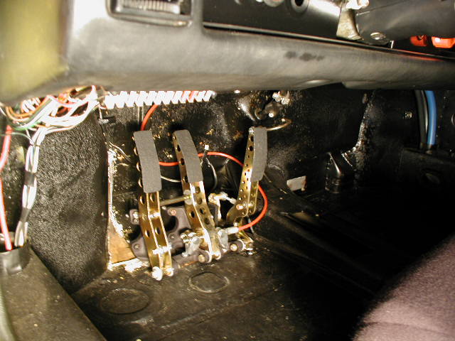 |
|
|
|
| byndbad914 |
Nov 26 2008, 06:33 PM
Post
#5
|
|
shoehorn and some butter - it fits Group: Members Posts: 1,547 Joined: 23-January 06 From: Broomfield, CO Member No.: 5,463 Region Association: None |
note this had a rod end and a super simple bracket to hold the slave to the engine - the clutch was so stiff it bent that rod end day 1 (they aren't supposed to be used in shear and I know better so I expected it), so I instead welded up a steel 90deg bracket to attach to the back of the V8 with the adapter mount bolts.
Point is you can see the mod I did to the stock arm and how I mounted the slave in general (IMG:style_emoticons/default/smile.gif) 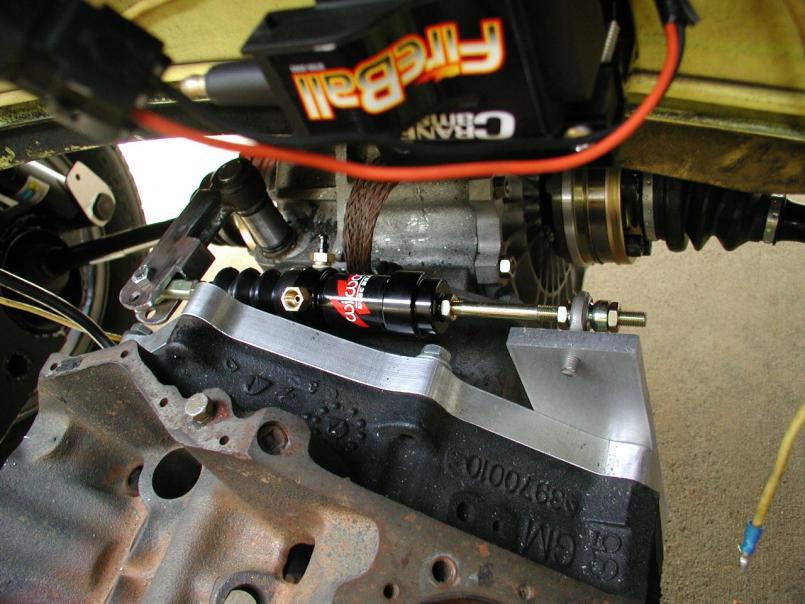 |
|
|
|
| burton73 |
Nov 26 2008, 06:43 PM
Post
#6
|
|
Senior member, and old dude Group: Members Posts: 4,050 Joined: 2-January 07 From: Los Angeles Member No.: 7,414 Region Association: Southern California |
This is the factory floor set up for a G-50 from a junkyard. The clutch pedal looks like it may be turned around. It may be possible to make 2 of these into one.
It may be possible to use a custom clutch cable to pull a master cylinder in the engine compartment to a different clutch master cylinder to the slave. Then I could stay with the standard pedals. Put a new reservoir in the engine compartment just for the hydraulic clutch worked by a clutch cable? Does that sound to weird? I just looked at the pan on a 914 and to put a factory part in right and I you would need to cut and weld in a second piece where the second master would go. Not sure but wanting to know from anyone that has done this. Thanks, Bob 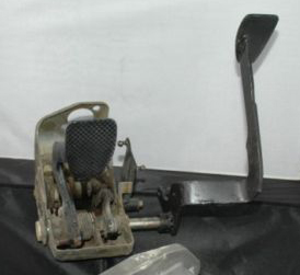 |
|
|
|
| burton73 |
Nov 26 2008, 06:49 PM
Post
#7
|
|
Senior member, and old dude Group: Members Posts: 4,050 Joined: 2-January 07 From: Los Angeles Member No.: 7,414 Region Association: Southern California |
You where on this faster than me.
Bob |
|
|
|
| andys |
Nov 26 2008, 06:55 PM
Post
#8
|
|
Advanced Member Group: Members Posts: 2,165 Joined: 21-May 03 From: Valencia, CA Member No.: 721 Region Association: None |
I mounted a Wilwood clutch master using a bellcrank setup off the stock pedal assembly. The master will eventually hide behind the console that I'm yet to install. This of course requires some amount of fabrication.
Consider also using the stock cable to actuate a master located next to the trans; use a similar bellcrank setup and a short hydraulic line. This avoids messing with stuff in the cramped space by the pedal cluster. Just a thought. Andys Attached thumbnail(s) 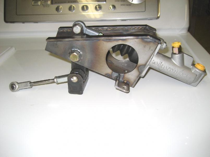 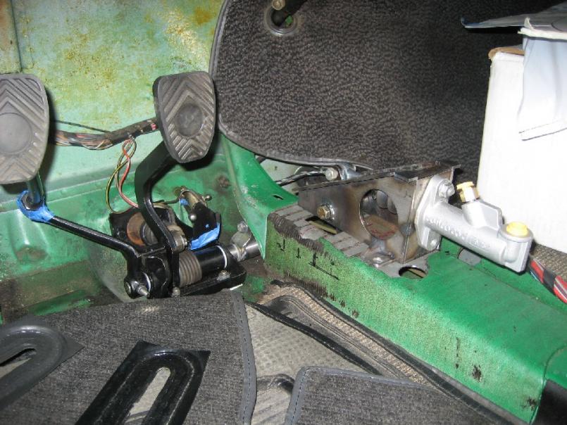
|
|
|
|
| Larry.Hubby |
Nov 26 2008, 07:30 PM
Post
#9
|
|
Member who doesn't post much, but has a long time in 914s Group: Members Posts: 191 Joined: 24-November 04 From: Palo Alto, CA Member No.: 3,172 Region Association: Northern California |
I mounted a stock 944 clutch master cylinder next to the brake master cylinder beneath the steering rack by making an aluminum adapter piece, creating an appropriate hole in the firewall, and then extending the clutch shaft of the stock 914 pedal assembly so it would line up and operate the 944 cylinder push rod with interfering with anything else. To do this you have to make three parts, the firewall adapter, the new pedal clutch shaft, and a spacer to hold the shaft in the right location, but, when you're done, the only part that might ever need replacing (the clutch master) is stock Porsche (and cheap stock Porsche at that, since it's a 944 part). Here's what it looks like from the underside:
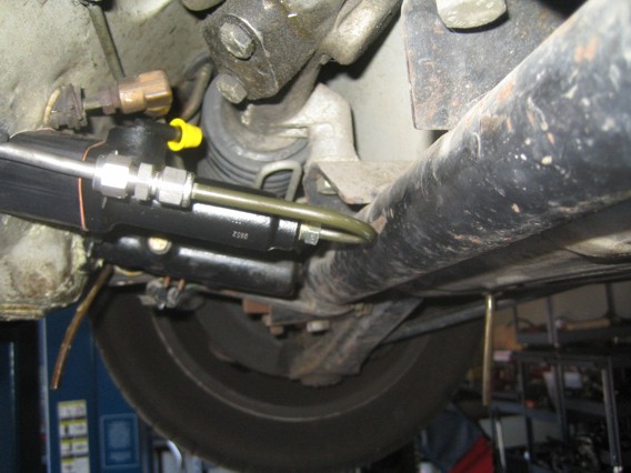 This is a view of the end of the clutch shaft inside the center tunnel in the passenger compartment: 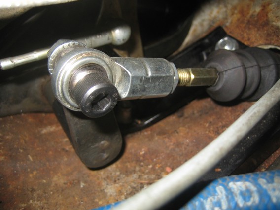 I believe there's some racing parts manufacturer that sells parts to do something similar, if you're not into making parts like this yourself. |
|
|
|
| burton73 |
Nov 26 2008, 09:41 PM
Post
#10
|
|
Senior member, and old dude Group: Members Posts: 4,050 Joined: 2-January 07 From: Los Angeles Member No.: 7,414 Region Association: Southern California |
You guys have given me some great ideas.
Andy’s idea “Consider also using the stock cable to actuate a master located next to the trans; use a similar bellcrank setup and a short hydraulic line. This avoids messing with stuff in the cramped space by the pedal cluster. Just a thought.” I said but could not put my words together. Larry, What is the yellow cap and what do you use for a reservoir on the 944 master if you need one at all? Does the aluminum adapter piece go in the inside? I am not into making any part that I can buy as there is too much to do and I am too old and my back is hurting. byndbad914, “I too used a Wilwood slave and simply welded box steel to the original clutch "arm" on the 930, then used that box steel to get some extra length to make clutch actuation a bit easier (the KEP PP is heavily sprung as you will find out).” All of you thanks for your help. Bob (IMG:style_emoticons/default/sawzall-smiley.gif) |
|
|
|
| Larry.Hubby |
Nov 27 2008, 01:38 AM
Post
#11
|
|
Member who doesn't post much, but has a long time in 914s Group: Members Posts: 191 Joined: 24-November 04 From: Palo Alto, CA Member No.: 3,172 Region Association: Northern California |
The yellow cap is just a plug on the input nipple of the 944 master (I hadn't hooked up the fluid reservoir yet when the picture was taken). The adapter piece is the black anodized aluminum part that the arrow points to in this photo:
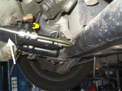 So, as you can see, it goes on the outside (but within the cavity for the steering rack, like the brake master cylinder, which is just behind it). The only thing complex about the part is that the face that goes against the firewall and the one that goes against the clutch master cylinder need to be at an angle of 25° to each other. The reservoir I used is the small one shown below. It's a brake reservoir from a 996 turbo, but I understand essentially the same reservoir was used on the early 356 models (before the advent of the tandem brake master cylinder). 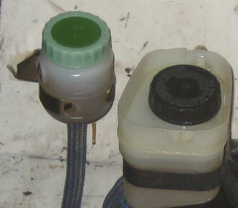 |
|
|
|
| burton73 |
Nov 27 2008, 06:07 PM
Post
#12
|
|
Senior member, and old dude Group: Members Posts: 4,050 Joined: 2-January 07 From: Los Angeles Member No.: 7,414 Region Association: Southern California |
“So, as you can see, it goes on the outside (but within the cavity for the steering rack, like the brake master cylinder, which is just behind it). The only thing complex about the part is that the face that goes against the firewall and the one that goes against the clutch master cylinder need to be at an angle of 25° to each other.”
Larry, It looks like your set up will be the easiest and cost less than the Tilton triple race set up but they sure look cool. It looks from your photo that the master for the brake and master for clutch end up at the same lever to the ground. Was that the 25 degrees you where pointing out and what is the thickness of that adapter? Did you just shape some stock you had around? I have a lot of High Density Polyethylene that sands nice on a 12” disk table grinder and drills very clean. That should work. It works for cutting boards. The backside of the clutch cable attachment point is where you think I will find some racing part made or McMaster Carr may have it. What is the black plate marked with white arrows? Blue arrow is the push side of the factory 944 master clutch cylinder. $100. With shipping on Ebay. Is this right. Thanks, Bob 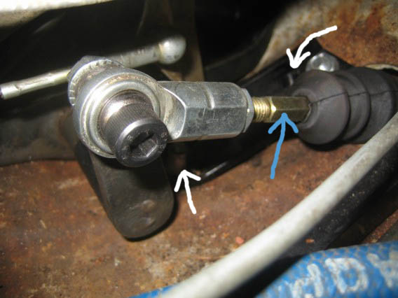 |
|
|
|
| Larry.Hubby |
Nov 29 2008, 03:59 PM
Post
#13
|
|
Member who doesn't post much, but has a long time in 914s Group: Members Posts: 191 Joined: 24-November 04 From: Palo Alto, CA Member No.: 3,172 Region Association: Northern California |
Sorry for the delay in answering your questions, the holiday intervened.
This is a diagram of the cavity for the steering rack and brake master cylinder seen from the passenger side: 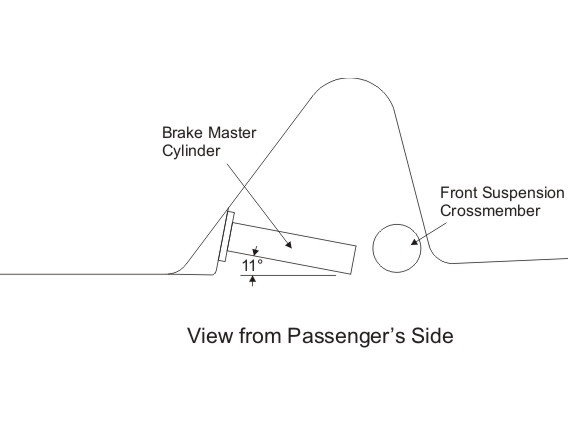 The brake MC is mounted on a specially stamped protrusion in the lower firewall, and is positioned with the front end down at about 11°. Presumably, this is to ensure that no air bubbles get trapped inside when the system is charged with fluid. We’re going to mount the MC for the clutch beside the brake MC, but closer to the passenger side. This means that it will have to mount to the more steeply-sloped part of the firewall, and we’ll need to position it at a downward angle, like the brake MC, for a similar reason. The situation we want to end up with looks like this: 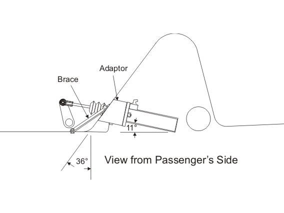 The adaptor required has to mount the clutch MC to the 36° part of the wall, yet leave the MC at an 11° angle, hence a 25° wedge angle is needed in this part. The drawing of the part I made for this is shown below: 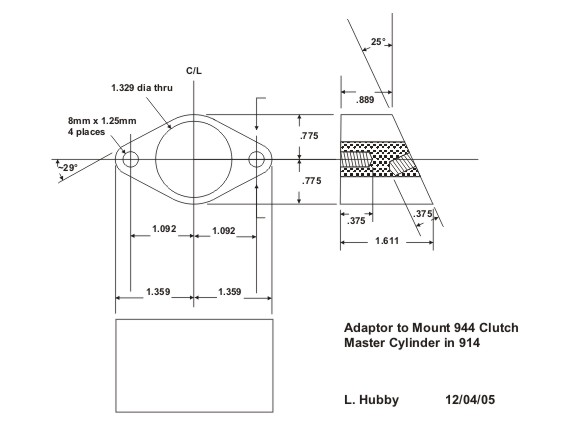 This part could be made simpler. It’s not necessary for the outside to be shaped like the gasket and mounting flange of the MC itself, but there are some nearby things that you will have to clear, such as the brake line to the rear of the car. Also, you could tap the mounting holes straight through (or drill a straight clearance hole and use a through bolt), but in that case you’d need to make some wedged washers or some such thing to go under the nuts or bolt heads on the inside of the firewall to deal with the fact that the bolts would be at 25° to the sheet metal. The black parts you asked about in the photo of the area around the clutch shaft are the braces shown on the second diagram. I added these in an attempt to reduce possible metal fatigue in the area due to repeated flexing from the force of operating the clutch. After getting it all together, however, I’m not sure these are required, as there seems to be very little flexing even with them unbolted. They’re black in the photo because I made them out of aluminum and had them black anodized, like the adaptor, but you could equally well make them from sheet metal, if you use them at all. Once you have the adaptor, you need to know where to mount it. This diagram should help with that: 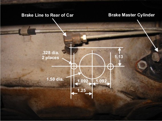 The exact location isn’t terribly critical. If it’s off by a bit in either direction, or in angle, it won’t matter much. There is enough flexibility in the push rod linkage to accommodate some misalignment. A clevis is used in the original 944 application to link the push rod to the clutch pedal. I used a standard 8mm rod end with female threads instead because I wanted to be sure I had as much flexibility as possible to accommodate possible relative miss-location of the clutch shaft and the clutch MC. The rod end will screw right onto the stock push rod, no modifications necessary. The only other thing you need is some form of extended clutch release shaft. I made a new one, following the general design practice of the factory. In the 911 models that use the 915 transmission, the factory extended and lengthened this shaft like we need to. The way that worked is that the shaft is longer, with a longer lever welded to the end, and the way the fact that the shaft is now longer than the bearing tube is handled is with a plastic spacer that goes onto the shaft before it’s inserted into the bearing tube and fills up the extra space. If my description is confusing, have a look at this diagram from PET. The clutch release shaft is 11, the spacer is 34, and the bearing tube is 9: 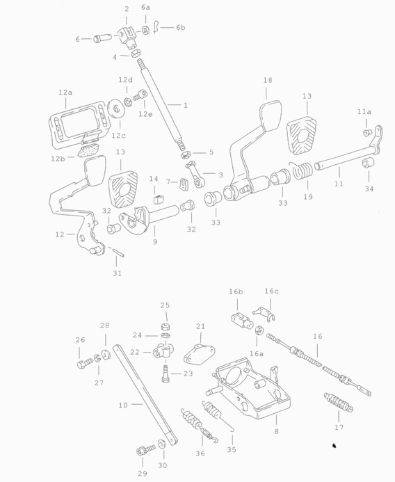 The only reason the shaft needed to be extended in the 911 case, is that the longer arm would otherwise interfere with the throttle linkage right above it. In our case, we have that problem, plus the fact that we need to align with the clutch MC, which is mounted to the right. The drawings for the parts I made are show below: 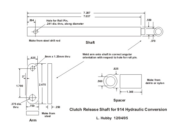 If this is too much machine work for your situation, you could possibly make an extension that bolts or welds onto the stock 914 shaft. Just remember that the offset to the right has to happen no further toward the end of the arm than the stock 914 arm length to avoid interfering with the throttle. If you did it this way, no spacer would be needed. If you make a custom shaft, as I did, you have to align the arm to the shaft with the hole for the roll pin that secures the shaft to the pedal in the right angular position relative to the arm. The same relative orientation as the stock 914 works fine for this arrangement. An easy way to do this is to pin the roll pin holes of both the new shaft and the stock 914 shaft together with a single straight pin (a long 6mm bolt works well), put the arm on the shaft and turn it to be parallel to the 914 arm, mark it, then later use the marks to align the arm and weld it solid. Once again, it doesn’t have to be super accurate – off a degree or two won’t matter. 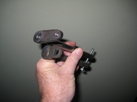 Good luck if you decide to go this way. |
|
|
|
| Dr Evil |
Nov 29 2008, 04:41 PM
Post
#14
|
|
Send me your transmission! Group: Members Posts: 23,044 Joined: 21-November 03 From: Loveland, OH 45140 Member No.: 1,372 Region Association: MidAtlantic Region |
Larry, you are amazing. I am glad you are on our site. I am motivated to do this conversion now just because you make it look correct (IMG:style_emoticons/default/wink.gif)
|
|
|
|
| Wilhelm |
Nov 29 2008, 07:26 PM
Post
#15
|
|
Member Group: Members Posts: 408 Joined: 7-September 07 From: Hooterville, OR Member No.: 8,088 Region Association: None |
I derived a similar solution. This way I can work on my car forever and not get to drive it! (IMG:style_emoticons/default/dry.gif)
Made a template of 16 gauge sheet metal with this pattern. Folded it at the line to 90 degrees. Cut a hurking hole in the floor and welded it in. 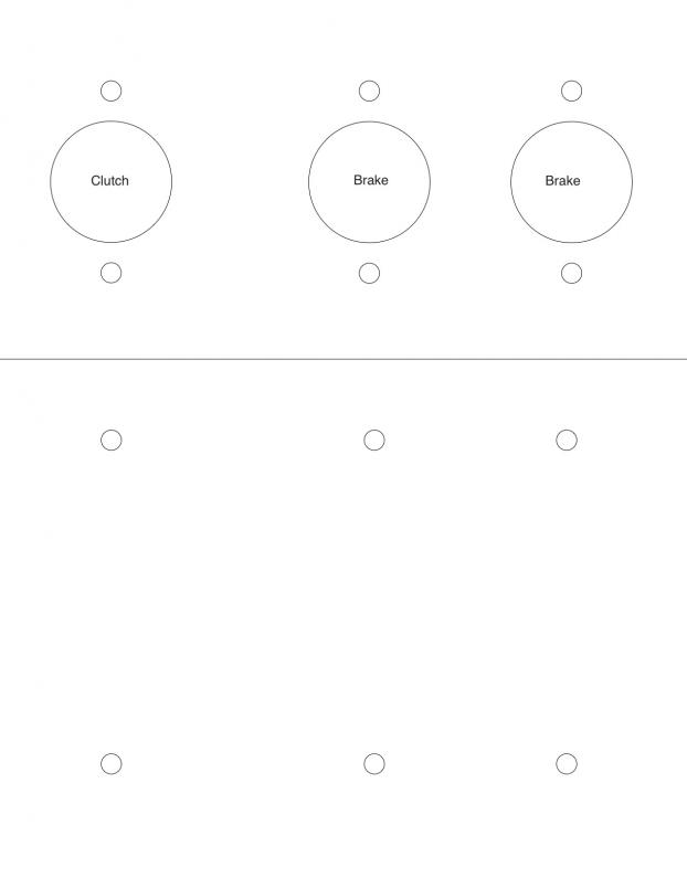 Here is a view from inside the compartment. Using wilwood pedals 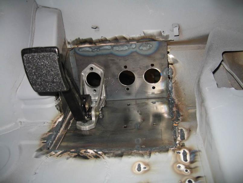 Another view form inside the drivers compartment. 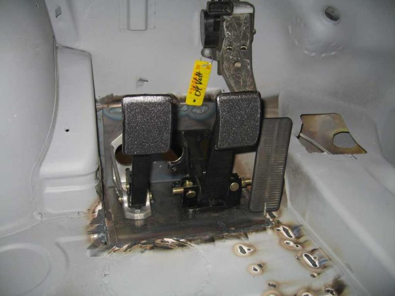 For Cylinders I'm using Tilton 75-series Master Cylinders as they are quite short and won't interfere with the rack. |
|
|
|
| burton73 |
Nov 30 2008, 12:25 PM
Post
#16
|
|
Senior member, and old dude Group: Members Posts: 4,050 Joined: 2-January 07 From: Los Angeles Member No.: 7,414 Region Association: Southern California |
I have decided to install a full late Carrera suspension with the aluminum cross bar. Do you think it will infer with the clearance of the MC, as it is a different shape. If these where machined by someone outside it would cost less if more than one set was made. Evil one, are you up for this? Larry thanks for your drawings and spending the time explaining this to us.
Wilhelm, What is the reason for 2 masters for the brakes? What and how is your throttle cable going to run? Thank to all, Bob |
|
|
|
| burton73 |
Nov 30 2008, 01:25 PM
Post
#17
|
|
Senior member, and old dude Group: Members Posts: 4,050 Joined: 2-January 07 From: Los Angeles Member No.: 7,414 Region Association: Southern California |
Wilhelm,
I find the Clutch pedal Wilwood 340-1289 $62.95 on the web but can not find the double brake unit. If a person were to run a 914-6 GT rear so the brake matches the front, why would you need the double MC? Where did you get your throttle set up? Thanks, Bob |
|
|
|
| burton73 |
Nov 30 2008, 04:16 PM
Post
#18
|
|
Senior member, and old dude Group: Members Posts: 4,050 Joined: 2-January 07 From: Los Angeles Member No.: 7,414 Region Association: Southern California |
I have found the Wilwood Part Number: 340-1285 $112. but is looks a little thinner in the back than yours. It that true?
Bob 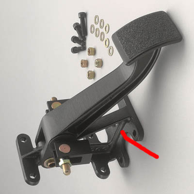 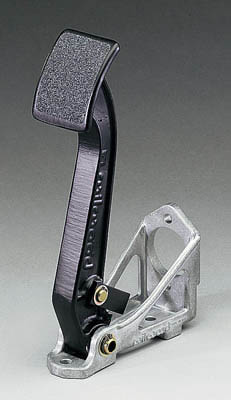 |
|
|
|
| Wilhelm |
Nov 30 2008, 05:44 PM
Post
#19
|
|
Member Group: Members Posts: 408 Joined: 7-September 07 From: Hooterville, OR Member No.: 8,088 Region Association: None |
That would be the correct double cylinder pedal part. I am going two master cylinders, 1 front and 1 rear. The wilwood double cylinder pedal acts as a balance bar to help distribute the correct amount of push to each system. If you look on the http://tiltonracing.com/content.php?page=faq&view=9 site they have a form you fill out listing your cars weight, style of calipers, caliper piston size, etc. Email this to them and within a day they will calculate what sizes of master cylinders you need. If you use the Tilton 75 series master cylinders http://tiltonracing.com/content.php?page=l...p;id=23&m=b , they are very short and you should be able to clear the rack. If you look closely the throttle pedal has a label that says "04 vette". There will be no throttle cable as this is a "drive by wire" throttle pedal for a 05 LS2 GM engine.
|
|
|
|
| burton73 |
Nov 30 2008, 07:16 PM
Post
#20
|
|
Senior member, and old dude Group: Members Posts: 4,050 Joined: 2-January 07 From: Los Angeles Member No.: 7,414 Region Association: Southern California |
If you look closely the throttle pedal has a label that says "04 vette". There will be no throttle cable as this is a "drive by wire" throttle pedal for a 05 LS2 GM engine.
[/quote] I understand now. One question on the drive by wire? Do you get just the pedal and part for the wall for the LS2 GM engine and on the other side what do you need? If you did not use this set up what where you’re thinking for the throttle? Thanks, Bob |
|
|
|
|
1 User(s) are reading this topic (1 Guests and 0 Anonymous Users)
0 Members:

|
Lo-Fi Version | Time is now: 20th July 2026 - 05:58 PM |
Invision Power Board
v9.1.4 © 2026 IPS, Inc.