|
|
|
Porsche, and the Porsche crest are registered trademarks of Dr. Ing. h.c. F. Porsche AG.
This site is not affiliated with Porsche in any way. Its only purpose is to provide an online forum for car enthusiasts. All other trademarks are property of their respective owners. |
|
|

  |

| Rotary'14 |
 Jan 19 2009, 08:36 PM Jan 19 2009, 08:36 PM
Post
#1
|
|
Senior Member  Group: Members Posts: 753 Joined: 24-April 05 From: Los Angeles Member No.: 3,977 |
Porsche Gauge illumination upgrade/modification.
For this write up I’ve used a 914 Tachometer, but the method is similar for other Porsche VDO gauges. Pointers appear dim, but this is a short coming of my camera. In real life pointers are easy to see. Tools you will need: Small flat screwdriver Scissors Soldering Iron Wire stripper Crimp tool Parts you will need: 2 wire connectors wire Small diameter heat shrink tubing Clear packaging plastic(saved from trash) Scotch tape solder 5 feet of Electro Luminesent wire 12v inverter for above wire Gauge Dis-assembly: First thing is to open up the gauge. This is done by prying at the bezel with a small screwdriver. Work around ¾ of the circumference of the gauge. It should be possible to remove the front trim bezel holding the lens in place. Beneath the lens is one or two additional bezel trim pieces (depending upon year of gauge). Examine the rear of the gauge and you should notice 3 or 4 small flat head screws. These hold the gauge mechanism in place. CAREFULLY remove the mechanism by loosening the screws, and set the mechanism aside. Attached image(s) 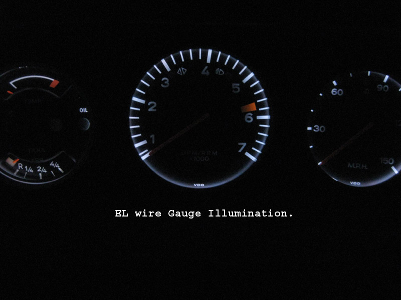 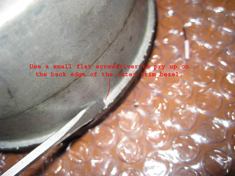 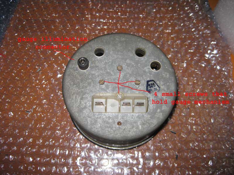 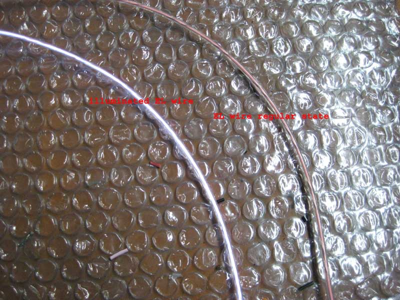
|
   |

 
|
| Rotary'14 |
Jan 19 2009, 08:40 PM
Post
#2
|
|
Senior Member Group: Members Posts: 753 Joined: 24-April 05 From: Los Angeles Member No.: 3,977 |
Material Preparation:
Cut the clear packing plastic into small rectangular strips roughly 3”x2”. Fit to the empty gauge housing and cut to length. Notch one end of the plastic strip to support EL wire. Set aside plastic supports. Attached thumbnail(s) 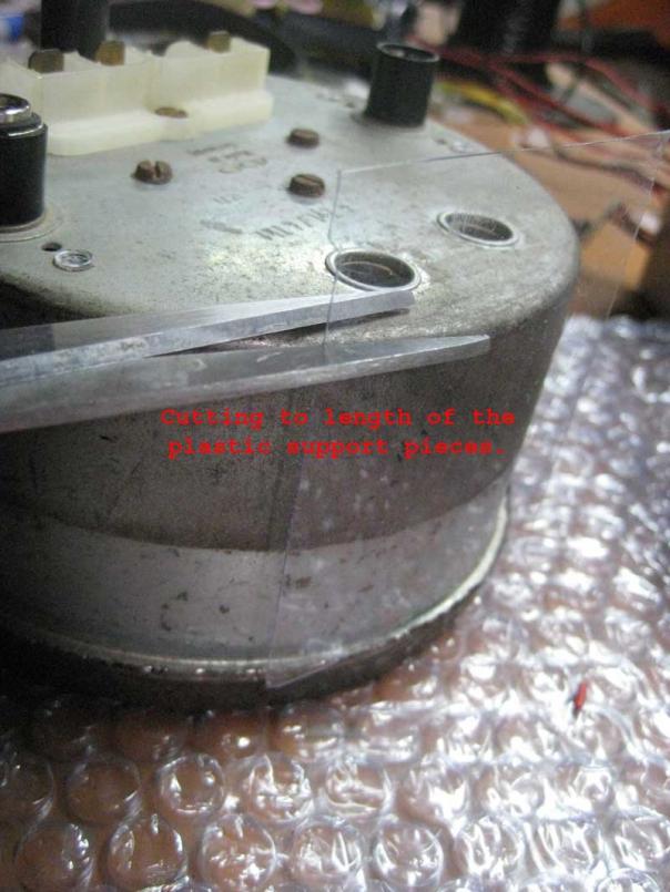 Attached image(s) 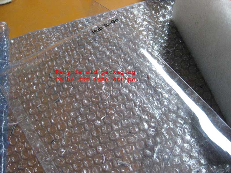 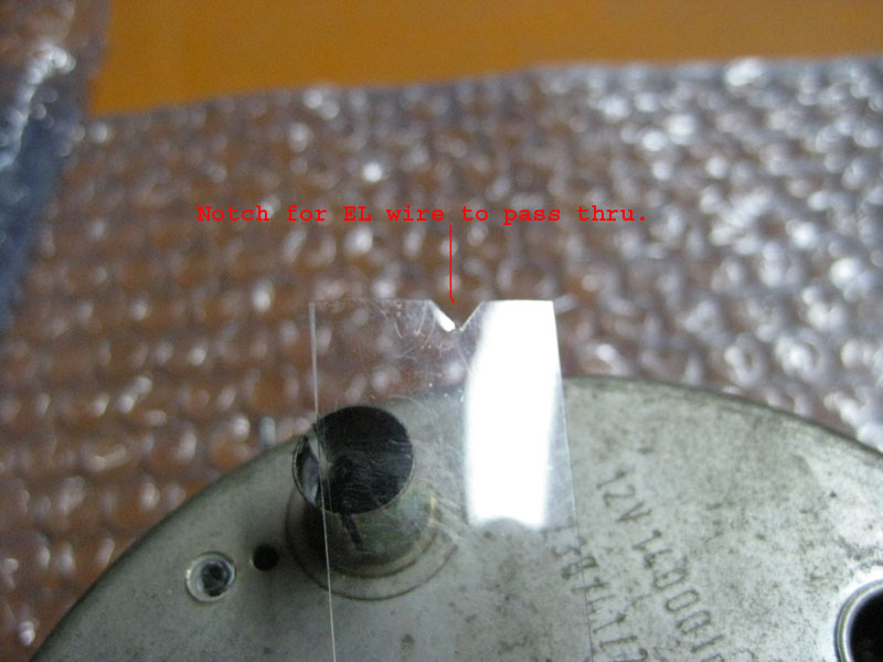
|
|
|
|
| Rotary'14 |
Jan 19 2009, 08:43 PM
Post
#3
|
|
Senior Member Group: Members Posts: 753 Joined: 24-April 05 From: Los Angeles Member No.: 3,977 |
Soldering EL wire:
Strip EL wire. There is a coated core,, and 1 or 2 very small wires. Remove the coating on the core by scratching/stripping/sanding. Connect wires from connector to EL wire, one wire to bare core, and other wire to the 1 or 2 very small wires. After assembling inverter outputs, check assembled wire to make sure things light up as expected. Attached image(s) 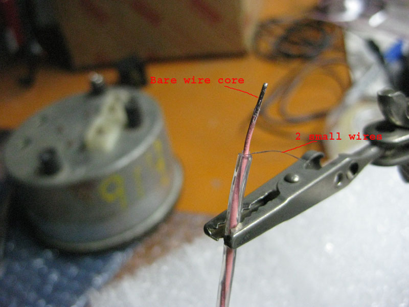 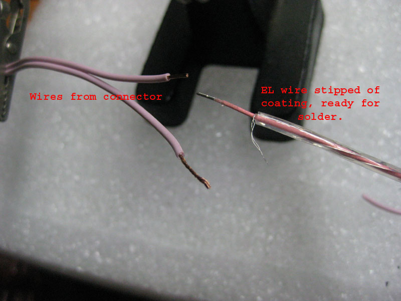 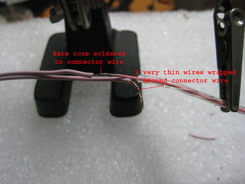 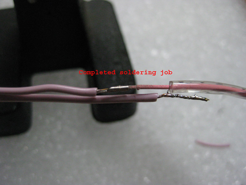
|
|
|
|
| Rotary'14 |
Jan 19 2009, 08:44 PM
Post
#4
|
|
Senior Member Group: Members Posts: 753 Joined: 24-April 05 From: Los Angeles Member No.: 3,977 |
We only need one inverter for any number of gauges. This inverter gets it’s power from the original lighting circuit off the dimmer. Yes the dimmer works too!! It’s a simple 2 wire installation. This inverter’s output needs to be split as many times as there are gauges. I chose to use a quick connect to make service/installation easier. Attached image(s)  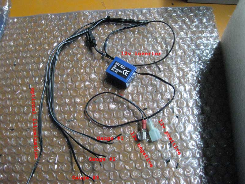
|
|
|
|
| Rotary'14 |
Jan 19 2009, 08:47 PM
Post
#5
|
|
Senior Member Group: Members Posts: 753 Joined: 24-April 05 From: Los Angeles Member No.: 3,977 |
Installation into Gauge:
Route EL wire thru the socket originally used for gauge illumination. Position the un-lit regular wire portion to either top or bottom of the gauge face. Position the EL wire by gently bending it along circumference of gauge. Test fit trim bezel from beneath the lens on the gauge housing. Trim off any overlapping EL wire. Secure in place by taping wire to plastic support. Use 3 or 4 along the circumference of the gauge. Test fit gauge mechanism back into gauge housing. Insure that no wires interfere with the action of the gauge mechanism. Hold lens in place over trim bezels and look for EL wire. It should be tucked up nice and tight beneath trim bezel, and should NOT be visible from the side of an assembled gauge Attached image(s) 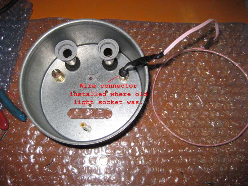 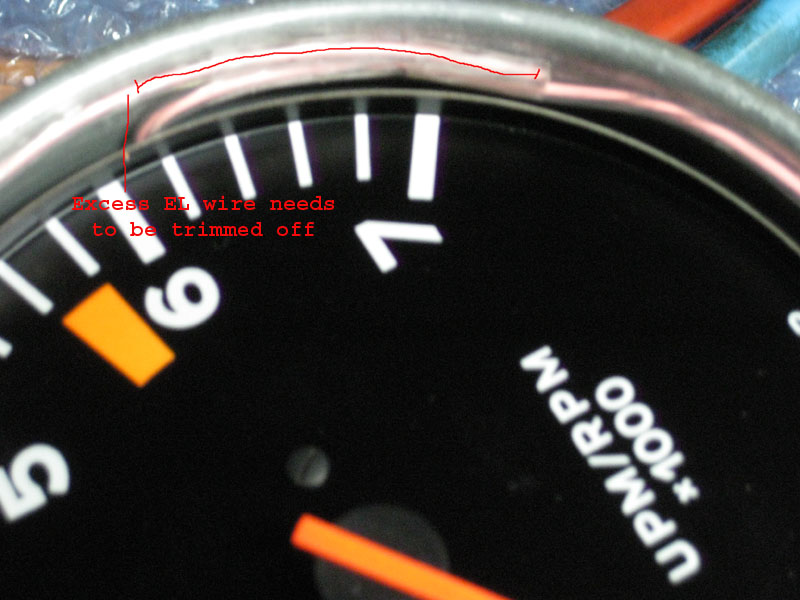 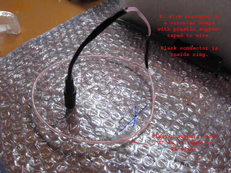 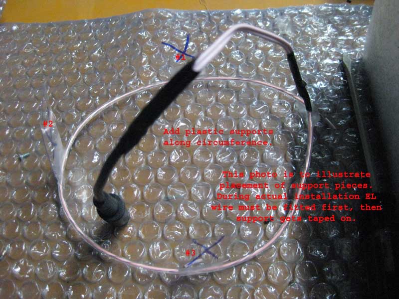
|
|
|
|
| Rotary'14 |
Jan 19 2009, 08:48 PM
Post
#6
|
|
Senior Member Group: Members Posts: 753 Joined: 24-April 05 From: Los Angeles Member No.: 3,977 |
Hold lens in place over trim bezels and look for EL wire. It should be tucked up nice and tight beneath trim bezel, and should NOT be visible from the side of an assembled gauge.
If all things look good, go ahead and re-assemble the gauge, by snapping the outer trim bezel on. Don’t re bend the bezel yet,, we need to test the gauge lighting. After gauge passes lighting test, seal it back up the best you can, by bending over the back of the outer bezel. Repeat above procedure for as many gauges as you have in your car. If you also want to illuminate your glove box,, 2 small holes is all you need. Please remember to be tasteful in the application of accent lighting. Attached image(s)  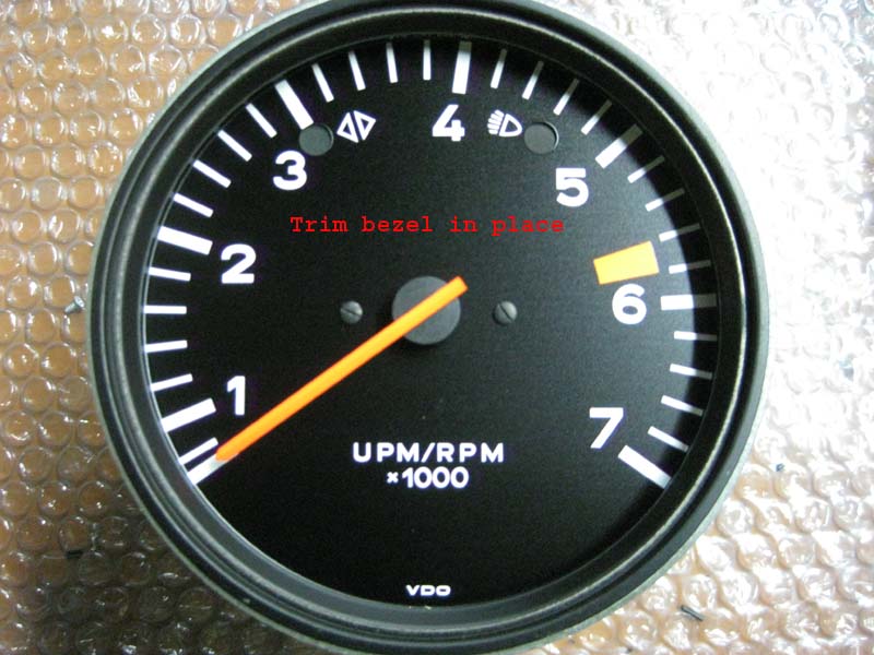
|
|
|
|
| Rotary'14 |
Jan 19 2009, 08:51 PM
Post
#7
|
|
Senior Member Group: Members Posts: 753 Joined: 24-April 05 From: Los Angeles Member No.: 3,977 |
Installation of modded gauges into car:
Disconnect all gauge illumination wires. Black with a Blue tracer in my case. Bundle up all loose ends and leave the very last one free. Insulate the bundled loose ends with black tape. Connect lone free illumination connector to the positive lead of the 12V inverter. Piggy back the ground connector of the 12V inverter to the ground point of the gauge. From the 12V inverter there should be a connector wired up for each of the gauges, as well as any additional points that need illumination. Connect each gauge to each connector. Congratulations, you are done. Flick on the lights and admire your hard work. The gauges illuminates just like a new car. Attached image(s) 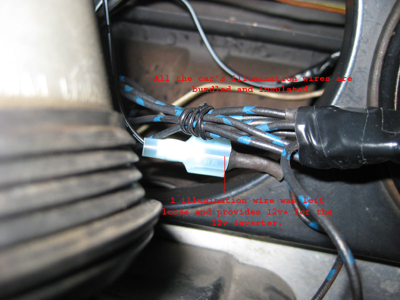 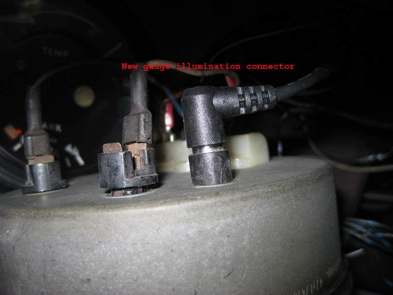 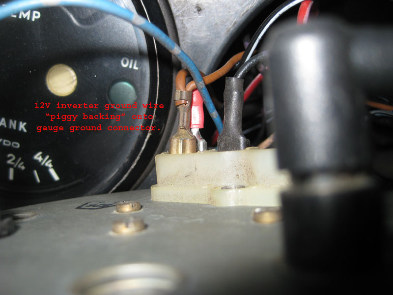 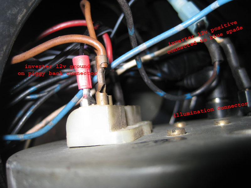
|
|
|
|
| Rotary'14 |
Jan 19 2009, 08:55 PM
Post
#8
|
|
Senior Member Group: Members Posts: 753 Joined: 24-April 05 From: Los Angeles Member No.: 3,977 |
And if you found the above a little too daunting,, I would be happy to offer a service of fitting these nifty light rings in. Drop me an email with your needs.
Can anybody give me any information on a "professional" gauge trim ring crimper? I'd love to crimp the trim rings back on in a professional manner. And before I get asked,, yes this set up works with the original dimmer. -Rob |
|
|
|
| StratPlayer |
Jan 19 2009, 10:29 PM
Post
#9
|
|
StratPlayer Group: Members Posts: 3,265 Joined: 27-December 02 From: SLC, Utah Member No.: 27 Region Association: Rocky Mountains |
(IMG:style_emoticons/default/smilie_pokal.gif) Very good..
|
|
|
|
| Dr Evil |
Jan 19 2009, 10:40 PM
Post
#10
|
|
Send me your transmission! Group: Members Posts: 22,995 Joined: 21-November 03 From: Loveland, OH 45140 Member No.: 1,372 Region Association: MidAtlantic Region |
Very novel and cool!
|
|
|
|
| 913B |
Jan 19 2009, 11:30 PM
Post
#11
|
|
Senior Member Group: Members Posts: 845 Joined: 25-April 05 From: South Bay/SoCal Member No.: 3,983 Region Association: None |
Robert, looks very good, so does it come in different colors ? Does it draw too much power to tax the factory wiring or is it wise to run another set of wires for it ?
Thanks for the info. |
|
|
|
| StratPlayer |
Feb 14 2009, 11:57 AM
Post
#12
|
|
StratPlayer Group: Members Posts: 3,265 Joined: 27-December 02 From: SLC, Utah Member No.: 27 Region Association: Rocky Mountains |
Great idea and it works very well, I used the 5m orange el wire, it fit in the gauges just fine and can't be seen. I used a 3 way pigtail coming off the inverter and its just a quick disconnect to plug or unplug the gauges.
I'm including a pic of the gauges lite up, the picture doesn't do the lighted gauges any justice. The gauges came out great very happy with the results and it was an easy job. Thanks for the thread on how this is done. Attached image(s) 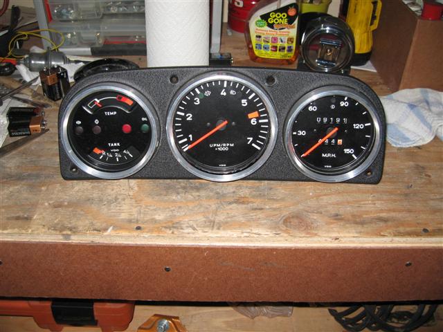 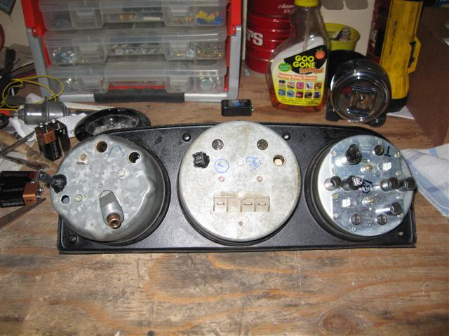 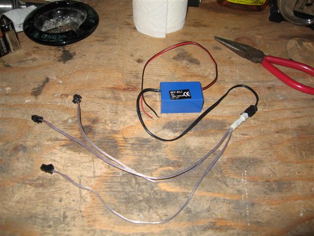
|
|
|
|
| StratPlayer |
Feb 14 2009, 11:59 AM
Post
#13
|
|
StratPlayer Group: Members Posts: 3,265 Joined: 27-December 02 From: SLC, Utah Member No.: 27 Region Association: Rocky Mountains |
jlkjlkjlk
Attached image(s) 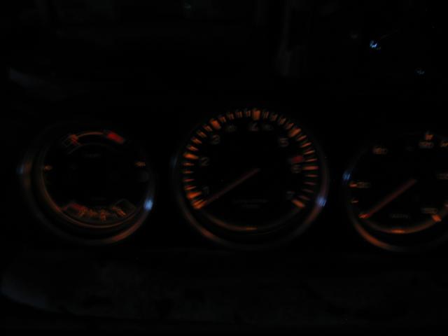
|
|
|
|
| charliew |
Feb 14 2009, 12:32 PM
Post
#14
|
|
Advanced Member Group: Members Posts: 2,363 Joined: 31-July 07 From: Crawford, TX. Member No.: 7,958 |
Do the plastic supports just sorta stand up on the sides and the gauge insides hold them against the sides? Could you use hot glue to glue the strip to the clear plastic as the scotch tape will age and fall apart I would think.
I found this: http://www.vibelights.com/elwiin.html Did you use the 3.2mm diameter wire? Will the 5mm fit? Does the wire you used go brighter than you would normally want so that it is adjustable? Nice job good idea! |
|
|
|
| Joe Bob |
Feb 14 2009, 12:50 PM
Post
#15
|
|
Retired admin, banned a few times Group: Members Posts: 17,427 Joined: 24-December 02 From: Boulder CO Member No.: 5 Region Association: None |
BTW, painting the inside of the buckets, white, is a big help.....
|
|
|
|
| ssstikircr |
Feb 14 2009, 01:02 PM
Post
#16
|
|
Member Group: Members Posts: 199 Joined: 11-January 09 From: Fair Oaks, Ca Member No.: 9,920 Region Association: Northern California |
Guys , WAY COOL job!! Gonna have to try that on my guages. (IMG:style_emoticons/default/beerchug.gif)
|
|
|
|
| StratPlayer |
Feb 14 2009, 01:29 PM
Post
#17
|
|
StratPlayer Group: Members Posts: 3,265 Joined: 27-December 02 From: SLC, Utah Member No.: 27 Region Association: Rocky Mountains |
I didn't use the plastic to hold the wire in place. I used the el wire holders. You can http://cgi.ebay.com/10-pieces-of-adhesive-...p4634.c0.m14get these on ebay. You can get your inverter from them as well.
The wire fits into these and then I just glue these in place, I used elmers glue and then held them with the el wire in the holders in place using clothes pins till the glue dries. I got the 5m orange wire and pigtails from here. http://www.thatscoolwire.com/store/subcate...bCategoryID=105. I ordered 5' of the orange wire, they cut the wire in equal sections then connected the clip on the end. Made it easy for the install. |
|
|
|
| Rotary'14 |
Feb 14 2009, 01:51 PM
Post
#18
|
|
Senior Member Group: Members Posts: 753 Joined: 24-April 05 From: Los Angeles Member No.: 3,977 |
I am so happy somebody else decided to give this a try!! Stratplayer,, my hat's off to you.
QUOTE(mikez @ Feb 14 2009, 10:50 AM)  BTW, painting the inside of the buckets, white, is a big help..... Hi Mr Z (IMG:style_emoticons/default/biggrin.gif) I'm sure that helps when the bulbs are in the buckets,,,, but these light wires are above the face behind the bezel and shines down on the face. -Rob (IMG:style_emoticons/default/biggrin.gif) |
|
|
|
| Rotary'14 |
Sep 15 2010, 05:46 PM
Post
#19
|
|
Senior Member Group: Members Posts: 753 Joined: 24-April 05 From: Los Angeles Member No.: 3,977 |
Anybody want a kit or have this done to their gauges? Feel free to PM me or reply here. I have about 5 kits of white EL wire parts lying around.
3 gauge kit $55 shipped. 5 gauge kit $60 shipped. |
|
|
|
| StratPlayer |
Sep 15 2010, 06:39 PM
Post
#20
|
|
StratPlayer Group: Members Posts: 3,265 Joined: 27-December 02 From: SLC, Utah Member No.: 27 Region Association: Rocky Mountains |
I had a chance to show how well this set up works at the RRC in moab last weekend. The folks that saw my gauges were impressed and I explained how easy it was to do this to the gauges. Great Idea, Works Great..... (IMG:style_emoticons/default/smilie_pokal.gif) (IMG:style_emoticons/default/smilie_pokal.gif)
|
|
|
|
|
1 User(s) are reading this topic (1 Guests and 0 Anonymous Users)
0 Members:

|
Lo-Fi Version | Time is now: 27th April 2024 - 05:42 AM |
Invision Power Board
v9.1.4 © 2024 IPS, Inc.