|
|
|
Porsche, and the Porsche crest are registered trademarks of Dr. Ing. h.c. F. Porsche AG.
This site is not affiliated with Porsche in any way. Its only purpose is to provide an online forum for car enthusiasts. All other trademarks are property of their respective owners. |
|
|


| FourBlades |
 Jan 21 2009, 08:54 PM Jan 21 2009, 08:54 PM
Post
#561
|
|
From Wreck to Rockin  Group: Members Posts: 2,056 Joined: 3-December 07 From: Brevard, FL Member No.: 8,414 Region Association: South East States |
I am finally starting on the build thread for the IMSA 914. This is a 1971 914-4
that was bought in 1975 or 6 as a used car and turned into an IMSA GTU car. It is a well crafted but not big budget car with a lot of clever touches that helped it to beat a lot of more famous and undoubtedly better financed teams. My wife and I plan to restore the car to racing condition and then enjoy the heck out of it without abusing it any further (its clearly had a hard life). Our priorities are (1) make it safe and legal for current vintage rules (2) keep it original as practical (3) keep it period correct, in that order. We also want to avoid over restoring it too much, but it is easy to understand the temptation to cad plate, power coat, and perfectly repaint everything. I think this last issue will be the biggest, other than going broke or insane first (either one would be a short trip at this point). I plan to post way too many photos, the best quality I can, until people flame me big time to stop. I also expect you, yes YOU!, to help me figure out what to do and give me ideas and comments. I may not always do everything people want, but I will consider all ideas. I'm really just a novice restorer and I know I can't do this without your help. OK, so screw the BS, lets see some pictures. (IMG:style_emoticons/default/aktion035.gif) Competing at Sebring as a 4-cylinder (changed to a six soon after). 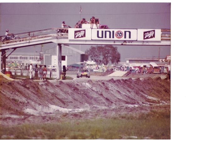 T.C., who found the car in a barn, passes it on to me (what luck!). 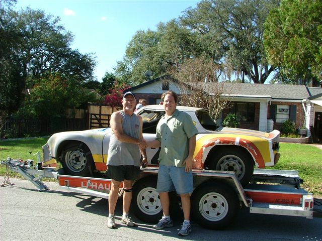 I had to turn to a close friend for the financing, but it worked out.  Huge ATL 500A fuel cell. The hood just closes over this.  TC, URY914, SMG914, and I working on my Explorer flat six conversion. 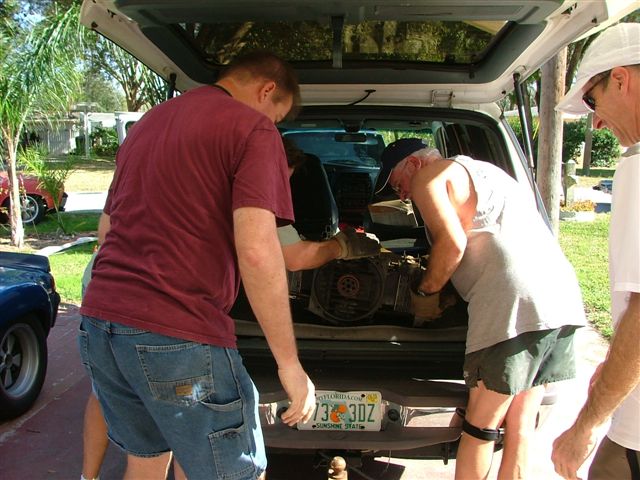 Fiberglass flares and paintwork need a little bit of work. 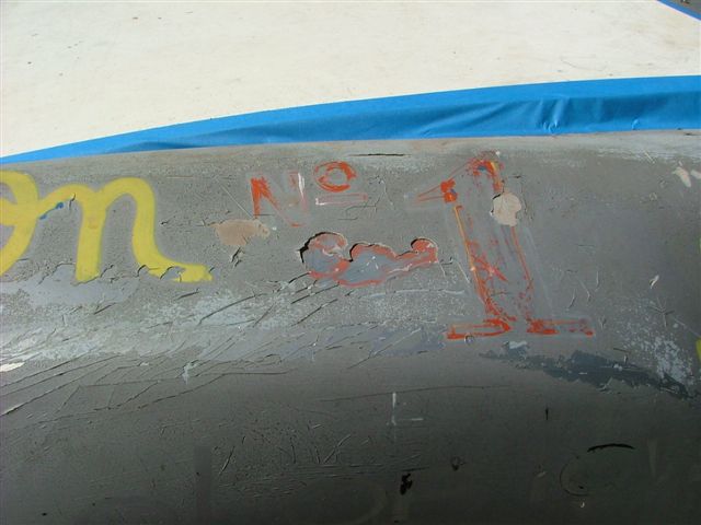 Wife: Are you sure we are buying the right car? Why don't we just buy this one from T.C., it actually has an engine inside the car. (IMG:style_emoticons/default/laugh.gif) 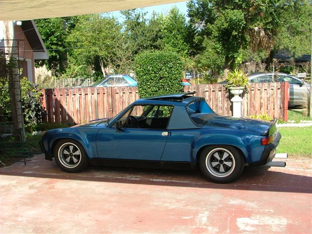 I have started to dissassemble the car so it can be soda blasted and I have tons of pictures to post. So what do you all think? John |
   |

 
|
Posts in this topic
 FourBlades Starting a 1971 IMSA 914 Restoration Jan 21 2009, 08:54 PM
 slow914 :flag1: :flag1: :flag1:
Post all the pictures ... Jan 21 2009, 09:00 PM championgt1 Cool project. Post lots of pics! :trophy: Jan 21 2009, 09:04 PM Todd Enlund This is gonna be awesome... :popcorn: Jan 22 2009, 01:27 AM Phoenix 914-6GT :agree: :Qarl: Jan 22 2009, 01:35 AM PanelBilly THe whole over restoration thing is a difficult on... Jan 22 2009, 01:55 AM carr914 Encouragement is right here across the State. Advi... Jan 22 2009, 06:35 AM FourBlades Thanks everyone for the encouragement.
Billy: I t... Jan 22 2009, 07:22 AM carr914 John, I told you I would dig up a picture of a Maz... Jan 22 2009, 07:27 AM sixnotfour
I think the term is sympathetic restoration.
Ke... Jan 22 2009, 08:06 AM Eric_Shea Did you take detailed photos of the graphics? Do ... Jan 22 2009, 03:41 PM JmuRiz Cool, and take/post all the pictures you want, the... Jan 22 2009, 03:47 PM sixnotfour I did a car with hand painted graphics and used tr... Jan 22 2009, 06:35 PM
slow914 :flag1: :flag1: :flag1:
Post all the pictures ... Jan 21 2009, 09:00 PM championgt1 Cool project. Post lots of pics! :trophy: Jan 21 2009, 09:04 PM Todd Enlund This is gonna be awesome... :popcorn: Jan 22 2009, 01:27 AM Phoenix 914-6GT :agree: :Qarl: Jan 22 2009, 01:35 AM PanelBilly THe whole over restoration thing is a difficult on... Jan 22 2009, 01:55 AM carr914 Encouragement is right here across the State. Advi... Jan 22 2009, 06:35 AM FourBlades Thanks everyone for the encouragement.
Billy: I t... Jan 22 2009, 07:22 AM carr914 John, I told you I would dig up a picture of a Maz... Jan 22 2009, 07:27 AM sixnotfour
I think the term is sympathetic restoration.
Ke... Jan 22 2009, 08:06 AM Eric_Shea Did you take detailed photos of the graphics? Do ... Jan 22 2009, 03:41 PM JmuRiz Cool, and take/post all the pictures you want, the... Jan 22 2009, 03:47 PM sixnotfour I did a car with hand painted graphics and used tr... Jan 22 2009, 06:35 PM
 FourBlades
I did a car with hand painted graphics and used t... Jan 22 2009, 08:20 PM turboman808 That's an awesome project :Qarl: Jan 22 2009, 06:48 PM Aaron Cox That will be a sick project! Jan 22 2009, 08:02 PM ericread So... Where the hell are the pictures <_<
... Jan 22 2009, 08:15 PM carr914 The Sponsor was Le Trianon Jewelry Corp - 3807 NW ... Jan 22 2009, 08:31 PM FourBlades No, T.C., I have not done that yet. I have worked... Jan 22 2009, 08:43 PM carr914 John, That Par filter was actually in-line for the... Jan 22 2009, 08:57 PM wertygrog COOL!
More pictures! :) Jan 24 2009, 12:05 AM FourBlades Thanks T.C. for the pictures. You know I will be ... Jan 24 2009, 07:32 PM FourBlades Found some wide, three piece Gotti wheels with Por... Jan 24 2009, 08:04 PM FourBlades Time to pull the fuel cell.
A vintage racing ra... Jan 24 2009, 08:11 PM FourBlades If anyone out there has pictures of this car from ... Jan 24 2009, 08:15 PM Lavanaut This is sweet, keep on posting them pics! :tr... Jan 24 2009, 09:23 PM FourBlades
This is sweet, keep on posting them pics! :t... Jan 24 2009, 10:16 PM markb
This is sweet, keep on posting them pics! :t... Jan 24 2009, 10:43 PM jc914 :popcorn: I will be following your rebuild you ha... Jan 25 2009, 08:46 AM FourBlades Pulled the fuel cell and checked it out. Might ne... Jan 29 2009, 07:42 PM FourBlades I screwed up the pictures in that last post about ... Jan 29 2009, 07:50 PM ssstikircr The pics are great keep them comming. Jan 29 2009, 07:57 PM carr914 I'd send that Fuel Cell back to ATL for warran... Jan 29 2009, 08:21 PM FourBlades Don't laugh, I am going to try it...
I read... Jan 29 2009, 08:24 PM FourBlades I need some help from you all. I am planning to u... Feb 26 2009, 08:22 AM carr914 John, I'll look through my receipts on my last... Feb 26 2009, 08:35 AM KevinP John,
Have you thought about the engine yet? I kn... Feb 26 2009, 08:46 AM FourBlades T.C. Glenn came by and took a bunch of pictures a... Feb 26 2009, 10:01 AM Al Meredith About 4 years ago I bought a 2.4L "T" en... Feb 26 2009, 05:43 PM FourBlades Al,
I would be very interested in an IMSA motor. ... Feb 28 2009, 07:44 PM sixnotfour I was thinking these would be cool on your car. Mar 1 2009, 09:55 PM carr914 Damn, what are those off, a Boeing 747?
And John,... Mar 2 2009, 07:35 AM sixnotfour
They were actually sold for 911's. 3 1/2 spac... Mar 2 2009, 09:52 PM FourBlades Those are some beefy looking calipers. Can you te... Mar 2 2009, 10:03 PM sixnotfour
:wacko:
BTW ralph m and company has the mold for... Mar 2 2009, 10:37 PM FourBlades Do you mean front caliper or bumper? I don't ... Mar 3 2009, 07:25 AM sixnotfour
Do you mean front caliper or bumper? I don't... Mar 3 2009, 09:33 AM ChicagoPete Doesn't Bernie Buschen have some 908 calipers ... Mar 3 2009, 06:21 PM sixnotfour http://www.roadglue.com/forum/showthread.php?t=521 Mar 3 2009, 09:02 PM krazykonrad :drooley: :drooley: :drooley: :drooley: !... Mar 3 2009, 09:50 PM FourBlades I have seen Bernie's thread on 908 calipers. ... Mar 4 2009, 08:10 AM carr914 Any updates John?
Here's an idea to update yo... Jul 14 2009, 07:04 PM ghuff That thing is *awesome*
Talk about a good find. P... Jul 14 2009, 09:39 PM FourBlades TC: I like the metal rocker, no termites or rot to... Jul 15 2009, 03:17 PM Cupomeat I am looking forward to the restart of the restora... Jul 15 2009, 03:57 PM gms get to work on this car :D Dec 3 2009, 10:31 PM FourBlades Hey Glenn,
Good to hear from you again! I ne... Dec 3 2009, 10:50 PM gms Here is some motivation, I finished one of my IMSA... Dec 4 2009, 09:02 PM carr914 Glenn, stick some Meats in the rear
T.C. Dec 5 2009, 06:50 AM gms
Glenn, stick some Meats in the rear
T.C.
That ... Dec 5 2009, 06:36 PM Racing916 spacers Dec 5 2009, 08:31 AM carr914 Glenn I have some 100mm studs if you need them.
T... Dec 6 2009, 06:52 AM FourBlades Glenn,
That looks great, you most be stoked! ... Dec 7 2009, 06:20 AM gms T.C. Thanks for the offer, I already have a set, j... Dec 7 2009, 08:37 AM FourBlades A picture Eric sent me today of the 908 repro cali... Mar 6 2010, 04:48 PM gms
A picture Eric sent me today of the 908 repro cal... Mar 7 2010, 10:03 PM Al Meredith John, I still have that 2.5L GTU engine, not a due... Mar 6 2010, 06:12 PM Eric_Shea One thing is done for this car... :D
Mar 7 2010, 10:22 AM kg6dxn
One thing is done for this car... :D
Those su... Mar 7 2010, 11:02 AM number6
One thing is done for this car... :D
YEOWSTER... Mar 7 2010, 08:08 PM carr914 That's some serious PORN right there. Deserves... Mar 7 2010, 05:53 PM Eric_Shea I know of another GT build that needs these... (be... Mar 7 2010, 06:07 PM carr914 I Don't Need No Stinkin Brakes :evilgrin:
... Mar 7 2010, 06:17 PM FourBlades Been stripping the car getting it ready for some r... Aug 22 2010, 09:57 AM URY914 John,
What do ya think, a month maybe 2 to get it... Aug 22 2010, 12:36 PM FourBlades I was thinking maybe a few hours and probably 3-4 ... Aug 22 2010, 01:55 PM carr914 Nevermind my post on your other thread, I thought ... Aug 22 2010, 02:59 PM FourBlades Looking at the struts and sway bars on the car. D... Nov 9 2010, 06:30 PM gms
Looking at the struts and sway bars on the car. ... Nov 9 2010, 08:14 PM FourBlades More hideous rust and damage pictures. The front... Nov 9 2010, 06:39 PM tscrihfield
More hideous rust and damage pictures. The fron... Nov 11 2010, 04:52 PM FourBlades
Thanks Thomas, that is great.
John Nov 13 2010, 08:58 PM FourBlades Been planning how the oil system will work. This ... Nov 9 2010, 06:53 PM gms John here is a diagram of oil system with cooler.
... Nov 9 2010, 08:09 PM FourBlades Thanks Glenn, I was hoping you would chime in.
Do... Nov 9 2010, 08:27 PM bcheney You're doing a great job John. This project is... Nov 9 2010, 09:04 PM sixnotfour Thats an old H&H sway bar Nov 9 2010, 09:57 PM gms
Thats an old H&H sway bar
You are right Jeff... Nov 10 2010, 08:07 AM pete000 I might have seen that car run at Sebring when I w... Nov 10 2010, 12:01 AM FourBlades They ran it as a 4 cylinder for a while and then w... Nov 10 2010, 06:26 AM FourBlades I wonder if the arms would fit on the new GPR bar?... Nov 10 2010, 10:29 AM URY914 John,
Anything you do to this car will be an imp... Nov 10 2010, 07:33 PM FourBlades Paul,
You have really put your finger on the prob... Nov 10 2010, 09:18 PM Racer Chris
If people have advice or opinions then please pos... Nov 13 2010, 07:54 AM URY914 John,
I'm glad you understand where I'm c... Nov 11 2010, 04:45 PM ME733 ......I think you have a great project there....an... Nov 13 2010, 01:14 PM sixnotfour
I thought they owned a jewlery business? The big... Nov 13 2010, 04:05 PM FourBlades
> Yes exactly, some regular guys go racing a... Nov 13 2010, 08:53 PM FourBlades Thanks very much for all the comments. It helps m... Nov 13 2010, 08:47 PM KELTY360
Today my buddy Sean (the Prawn) was over and we ... Nov 13 2010, 08:57 PM
FourBlades
I did a car with hand painted graphics and used t... Jan 22 2009, 08:20 PM turboman808 That's an awesome project :Qarl: Jan 22 2009, 06:48 PM Aaron Cox That will be a sick project! Jan 22 2009, 08:02 PM ericread So... Where the hell are the pictures <_<
... Jan 22 2009, 08:15 PM carr914 The Sponsor was Le Trianon Jewelry Corp - 3807 NW ... Jan 22 2009, 08:31 PM FourBlades No, T.C., I have not done that yet. I have worked... Jan 22 2009, 08:43 PM carr914 John, That Par filter was actually in-line for the... Jan 22 2009, 08:57 PM wertygrog COOL!
More pictures! :) Jan 24 2009, 12:05 AM FourBlades Thanks T.C. for the pictures. You know I will be ... Jan 24 2009, 07:32 PM FourBlades Found some wide, three piece Gotti wheels with Por... Jan 24 2009, 08:04 PM FourBlades Time to pull the fuel cell.
A vintage racing ra... Jan 24 2009, 08:11 PM FourBlades If anyone out there has pictures of this car from ... Jan 24 2009, 08:15 PM Lavanaut This is sweet, keep on posting them pics! :tr... Jan 24 2009, 09:23 PM FourBlades
This is sweet, keep on posting them pics! :t... Jan 24 2009, 10:16 PM markb
This is sweet, keep on posting them pics! :t... Jan 24 2009, 10:43 PM jc914 :popcorn: I will be following your rebuild you ha... Jan 25 2009, 08:46 AM FourBlades Pulled the fuel cell and checked it out. Might ne... Jan 29 2009, 07:42 PM FourBlades I screwed up the pictures in that last post about ... Jan 29 2009, 07:50 PM ssstikircr The pics are great keep them comming. Jan 29 2009, 07:57 PM carr914 I'd send that Fuel Cell back to ATL for warran... Jan 29 2009, 08:21 PM FourBlades Don't laugh, I am going to try it...
I read... Jan 29 2009, 08:24 PM FourBlades I need some help from you all. I am planning to u... Feb 26 2009, 08:22 AM carr914 John, I'll look through my receipts on my last... Feb 26 2009, 08:35 AM KevinP John,
Have you thought about the engine yet? I kn... Feb 26 2009, 08:46 AM FourBlades T.C. Glenn came by and took a bunch of pictures a... Feb 26 2009, 10:01 AM Al Meredith About 4 years ago I bought a 2.4L "T" en... Feb 26 2009, 05:43 PM FourBlades Al,
I would be very interested in an IMSA motor. ... Feb 28 2009, 07:44 PM sixnotfour I was thinking these would be cool on your car. Mar 1 2009, 09:55 PM carr914 Damn, what are those off, a Boeing 747?
And John,... Mar 2 2009, 07:35 AM sixnotfour
They were actually sold for 911's. 3 1/2 spac... Mar 2 2009, 09:52 PM FourBlades Those are some beefy looking calipers. Can you te... Mar 2 2009, 10:03 PM sixnotfour
:wacko:
BTW ralph m and company has the mold for... Mar 2 2009, 10:37 PM FourBlades Do you mean front caliper or bumper? I don't ... Mar 3 2009, 07:25 AM sixnotfour
Do you mean front caliper or bumper? I don't... Mar 3 2009, 09:33 AM ChicagoPete Doesn't Bernie Buschen have some 908 calipers ... Mar 3 2009, 06:21 PM sixnotfour http://www.roadglue.com/forum/showthread.php?t=521 Mar 3 2009, 09:02 PM krazykonrad :drooley: :drooley: :drooley: :drooley: !... Mar 3 2009, 09:50 PM FourBlades I have seen Bernie's thread on 908 calipers. ... Mar 4 2009, 08:10 AM carr914 Any updates John?
Here's an idea to update yo... Jul 14 2009, 07:04 PM ghuff That thing is *awesome*
Talk about a good find. P... Jul 14 2009, 09:39 PM FourBlades TC: I like the metal rocker, no termites or rot to... Jul 15 2009, 03:17 PM Cupomeat I am looking forward to the restart of the restora... Jul 15 2009, 03:57 PM gms get to work on this car :D Dec 3 2009, 10:31 PM FourBlades Hey Glenn,
Good to hear from you again! I ne... Dec 3 2009, 10:50 PM gms Here is some motivation, I finished one of my IMSA... Dec 4 2009, 09:02 PM carr914 Glenn, stick some Meats in the rear
T.C. Dec 5 2009, 06:50 AM gms
Glenn, stick some Meats in the rear
T.C.
That ... Dec 5 2009, 06:36 PM Racing916 spacers Dec 5 2009, 08:31 AM carr914 Glenn I have some 100mm studs if you need them.
T... Dec 6 2009, 06:52 AM FourBlades Glenn,
That looks great, you most be stoked! ... Dec 7 2009, 06:20 AM gms T.C. Thanks for the offer, I already have a set, j... Dec 7 2009, 08:37 AM FourBlades A picture Eric sent me today of the 908 repro cali... Mar 6 2010, 04:48 PM gms
A picture Eric sent me today of the 908 repro cal... Mar 7 2010, 10:03 PM Al Meredith John, I still have that 2.5L GTU engine, not a due... Mar 6 2010, 06:12 PM Eric_Shea One thing is done for this car... :D
Mar 7 2010, 10:22 AM kg6dxn
One thing is done for this car... :D
Those su... Mar 7 2010, 11:02 AM number6
One thing is done for this car... :D
YEOWSTER... Mar 7 2010, 08:08 PM carr914 That's some serious PORN right there. Deserves... Mar 7 2010, 05:53 PM Eric_Shea I know of another GT build that needs these... (be... Mar 7 2010, 06:07 PM carr914 I Don't Need No Stinkin Brakes :evilgrin:
... Mar 7 2010, 06:17 PM FourBlades Been stripping the car getting it ready for some r... Aug 22 2010, 09:57 AM URY914 John,
What do ya think, a month maybe 2 to get it... Aug 22 2010, 12:36 PM FourBlades I was thinking maybe a few hours and probably 3-4 ... Aug 22 2010, 01:55 PM carr914 Nevermind my post on your other thread, I thought ... Aug 22 2010, 02:59 PM FourBlades Looking at the struts and sway bars on the car. D... Nov 9 2010, 06:30 PM gms
Looking at the struts and sway bars on the car. ... Nov 9 2010, 08:14 PM FourBlades More hideous rust and damage pictures. The front... Nov 9 2010, 06:39 PM tscrihfield
More hideous rust and damage pictures. The fron... Nov 11 2010, 04:52 PM FourBlades
Thanks Thomas, that is great.
John Nov 13 2010, 08:58 PM FourBlades Been planning how the oil system will work. This ... Nov 9 2010, 06:53 PM gms John here is a diagram of oil system with cooler.
... Nov 9 2010, 08:09 PM FourBlades Thanks Glenn, I was hoping you would chime in.
Do... Nov 9 2010, 08:27 PM bcheney You're doing a great job John. This project is... Nov 9 2010, 09:04 PM sixnotfour Thats an old H&H sway bar Nov 9 2010, 09:57 PM gms
Thats an old H&H sway bar
You are right Jeff... Nov 10 2010, 08:07 AM pete000 I might have seen that car run at Sebring when I w... Nov 10 2010, 12:01 AM FourBlades They ran it as a 4 cylinder for a while and then w... Nov 10 2010, 06:26 AM FourBlades I wonder if the arms would fit on the new GPR bar?... Nov 10 2010, 10:29 AM URY914 John,
Anything you do to this car will be an imp... Nov 10 2010, 07:33 PM FourBlades Paul,
You have really put your finger on the prob... Nov 10 2010, 09:18 PM Racer Chris
If people have advice or opinions then please pos... Nov 13 2010, 07:54 AM URY914 John,
I'm glad you understand where I'm c... Nov 11 2010, 04:45 PM ME733 ......I think you have a great project there....an... Nov 13 2010, 01:14 PM sixnotfour
I thought they owned a jewlery business? The big... Nov 13 2010, 04:05 PM FourBlades
> Yes exactly, some regular guys go racing a... Nov 13 2010, 08:53 PM FourBlades Thanks very much for all the comments. It helps m... Nov 13 2010, 08:47 PM KELTY360
Today my buddy Sean (the Prawn) was over and we ... Nov 13 2010, 08:57 PM  |
1 User(s) are reading this topic (1 Guests and 0 Anonymous Users)
0 Members:

|
Lo-Fi Version | Time is now: 14th June 2026 - 04:33 PM |
Invision Power Board
v9.1.4 © 2026 IPS, Inc.