|
|
|
Porsche, and the Porsche crest are registered trademarks of Dr. Ing. h.c. F. Porsche AG.
This site is not affiliated with Porsche in any way. Its only purpose is to provide an online forum for car enthusiasts. All other trademarks are property of their respective owners. |
|
|


| Cevan |
 May 11 2009, 11:47 AM May 11 2009, 11:47 AM
Post
#1
|
|
Senior Member  Group: Members Posts: 1,079 Joined: 11-December 06 From: Western Massachusetts Member No.: 7,351 |
I've completed my 1.8 to 2.0 motor swap and have my car running really good, except the TPS is worn right around the partially open throttle position.
I've cleaned the surface and the contacts with 2000 grit sandpaper and then used Deoxit electrial contact cleaner. This helped as it only hesitates/bucks at the barely open throttle position and cleared up the issue at positions further along the path of travel. I imagine that it's worn right at the spot where you're most often running at. I searched but couldn't find any threads on repairing this. What I want to do is move the circuit board to the right or left, so that the contacts run on a fresh part of the board. Any ideas on how to separate the circuit board from the metal body and how best to reattach it? It looks like it may be soldered at the bottom right corner. 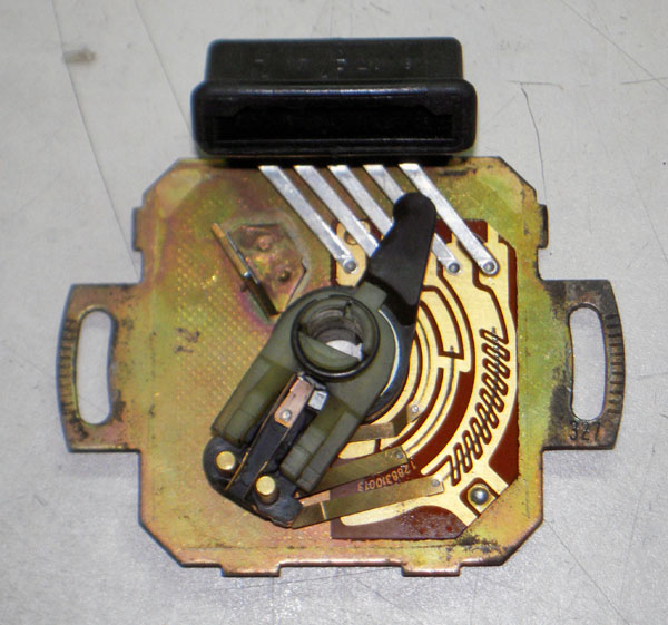 |
   |

 
|
Posts in this topic
 Cevan Throttle position switch (TPS) repair May 11 2009, 11:47 AM
 McMark Using careful pressure, you can slightly bend the ... May 11 2009, 11:50 AM
 Gint Using careful pressure, you can slightly bend the ... Jun 15 2009, 08:54 PM Cevan Thanks McMark. I did as you suggested and gently ... May 12 2009, 05:39 AM Derek Seymour I think this may have already been mentioned, but ... Jun 15 2009, 02:20 PM rjames
I think this may have already been mentioned, but... Jun 15 2009, 02:23 PM Cevan I fixed mine in about 10 minutes, from start to fi... Jun 15 2009, 02:31 PM Derek Seymour It may kill it for some but for others I suspect t... Jun 15 2009, 03:29 PM r_towle Isnt that gold?
Could gold leafbe applied tofix th... Jun 15 2009, 05:11 PM worn
Isnt that gold?
Could gold leafbe applied tofix t... Sep 27 2018, 01:28 AM davesprinkle I have a board house manufacturing these circuit b... Jun 15 2009, 07:14 PM Derek Seymour
I have a board house manufacturing these circuit ... Jun 15 2009, 08:09 PM mikeg4 [quote name='davesprinkle' date='Jun 1... Feb 16 2010, 08:31 PM davesprinkle
I have a board house manufacturing these circuit... Feb 16 2010, 09:02 PM Pat Garvey The the original on my 72 was never as worn as you... Jun 15 2009, 08:37 PM davesprinkle Circuit boards arrived. Here's a pic. Testin... Jun 22 2009, 08:49 AM davesprinkle More pics of initial board installation in this th... Jun 22 2009, 03:37 PM johnwmrvw Hello, I'm interested in your circuit board. I... Feb 10 2010, 09:44 PM McMark <_< Posting pictures here is apparently dif... Jun 23 2009, 01:00 AM davesprinkle
<_< Posting pictures here is apparently di... Jun 23 2009, 09:50 AM kwales Yeah, that's a really good picture on the othe... Jun 23 2009, 09:46 AM davesprinkle A business card makes a good ramp for getting the ... Jun 23 2009, 09:51 AM davesprinkle Here's a pic of the board with the business ca... Jun 23 2009, 09:51 AM davesprinkle Rivet installed. I would urge you to fend off the... Jun 23 2009, 09:54 AM davesprinkle Here is a pic with the connector reinstalled onto ... Jun 23 2009, 09:56 AM McMark
:rotfl: Yeah, about 1% of the same content and s... Jun 23 2009, 11:08 AM Jeff Bowlsby Thanks for making these Dave...we have been in nee... Jun 23 2009, 01:51 PM davesprinkle
Thanks for making these Dave...we have been in ne... Jun 23 2009, 02:19 PM Jeff Bowlsby That seems well thought out Dave. While a screw c... Jun 23 2009, 02:36 PM davesprinkle
That seems well thought out Dave. While a screw ... Jun 23 2009, 02:39 PM Jeff Bowlsby Thats great! I would be happy to be a 2.0L mu... Jun 23 2009, 03:17 PM warrenoliver
Thanks for making these Dave...we have been in n... Jun 24 2009, 05:02 PM davesprinkle
How about JB Weld? Wouldn't that work even... Jun 25 2009, 12:53 AM warrenoliver
How about JB Weld? Wouldn't that work eve... Jun 25 2009, 11:25 AM kwales Gee Jeff,
The answer to that is obvious....
Con... Jun 23 2009, 01:59 PM RoadGlue Subscribed to this thread. This looks awesome. Nic... Jun 23 2009, 03:12 PM Tom Dave,
Outstanding job. I remember doing some sma... Jun 23 2009, 03:49 PM Cevan Even though I fixed mine (at least temporarily), I... Jun 23 2009, 04:30 PM davesprinkle
Question: Is the conductive material on the board... Jun 23 2009, 06:45 PM davesprinkle Everyone, I still haven't found a suitable tes... Jun 29 2009, 10:23 PM sixnotfour dave a ,local shop told me AA has the boards too ?... Jun 29 2009, 11:27 PM davesprinkle
dave a ,local shop told me AA has the boards too ... Jun 29 2009, 11:44 PM davesprinkle I've got a late 1.7liter TPS here. It appears... Jun 30 2009, 02:26 PM Derek Seymour :bump: Jul 1 2009, 11:46 AM rjames I'm wishing my Seattle teener was in Portland ... Jul 1 2009, 01:36 PM davesprinkle Jeff Bowlsby installed the board on his 2.0liter. ... Jul 6 2009, 09:29 PM sixnotfour
Thanks for helping Mark . Jeff Jul 6 2009, 09:45 PM Mikey914 I have a 76 2.0 that is local. Unfortunately, I st... Jul 6 2009, 09:55 PM RoadGlue Bump! I REALLY want two of these ASAP. :) Any ... Jul 19 2009, 12:08 AM davesprinkle OK everybody, sorry for the delay. I've compl... Aug 24 2009, 10:53 PM RoadGlue Hooray! How do we order? Aug 24 2009, 11:49 PM davesprinkle
Hooray! How do we order?
You can either sen... Aug 25 2009, 08:42 AM RoadGlue I ordered two! Who's next?
*bump* Aug 25 2009, 03:35 PM davesprinkle
I ordered two! Who's next?
*bump*
Rand... Aug 25 2009, 06:37 PM davesprinkle I just received the boards for the late 1.7liter c... Jan 28 2010, 09:15 PM Rod
I just received the boards for the late 1.7liter ... Jan 29 2010, 12:29 PM davesprinkle
I just received the boards for the late 1.7liter... Jan 29 2010, 07:12 PM pbanders Dave, this is all great stuff! Awesome enginee... Jan 29 2010, 10:44 AM McMark Dave, could you add something in the Member Vendor... Feb 3 2010, 11:29 PM ericread I purchased and installed the new TPS, but I'l... Feb 17 2010, 05:19 PM davesprinkle
I purchased and installed the new TPS, but I... Feb 17 2010, 10:52 PM ericread
Eric, the switch is designed with hysteresis (ba... Feb 18 2010, 08:41 AM hushpuppy dave,
do you still have any of the boards left 7... Sep 21 2018, 06:57 PM jagalyn
dave,
do you still have any of the boards left ... Sep 26 2018, 08:17 PM ChrisFoley
dave,
do you still have any of the boards left... Sep 27 2018, 06:37 AM Mikey914
[quote name='jagalyn' post='2652419' date='Sep 26... Sep 29 2018, 10:31 PM davesprinkle
dave,
do you still have any of the boards left ... Sep 30 2018, 01:11 AM Tbrown4x4 914Rubber has the boards in stock.
Oops. I didn... Sep 27 2018, 02:44 AM jagalyn https://shop.914rubber.com/Porsche-914-Thro...m?ca... Sep 27 2018, 07:14 AM
Gint Using careful pressure, you can slightly bend the ... Jun 15 2009, 08:54 PM Cevan Thanks McMark. I did as you suggested and gently ... May 12 2009, 05:39 AM Derek Seymour I think this may have already been mentioned, but ... Jun 15 2009, 02:20 PM rjames
I think this may have already been mentioned, but... Jun 15 2009, 02:23 PM Cevan I fixed mine in about 10 minutes, from start to fi... Jun 15 2009, 02:31 PM Derek Seymour It may kill it for some but for others I suspect t... Jun 15 2009, 03:29 PM r_towle Isnt that gold?
Could gold leafbe applied tofix th... Jun 15 2009, 05:11 PM worn
Isnt that gold?
Could gold leafbe applied tofix t... Sep 27 2018, 01:28 AM davesprinkle I have a board house manufacturing these circuit b... Jun 15 2009, 07:14 PM Derek Seymour
I have a board house manufacturing these circuit ... Jun 15 2009, 08:09 PM mikeg4 [quote name='davesprinkle' date='Jun 1... Feb 16 2010, 08:31 PM davesprinkle
I have a board house manufacturing these circuit... Feb 16 2010, 09:02 PM Pat Garvey The the original on my 72 was never as worn as you... Jun 15 2009, 08:37 PM davesprinkle Circuit boards arrived. Here's a pic. Testin... Jun 22 2009, 08:49 AM davesprinkle More pics of initial board installation in this th... Jun 22 2009, 03:37 PM johnwmrvw Hello, I'm interested in your circuit board. I... Feb 10 2010, 09:44 PM McMark <_< Posting pictures here is apparently dif... Jun 23 2009, 01:00 AM davesprinkle
<_< Posting pictures here is apparently di... Jun 23 2009, 09:50 AM kwales Yeah, that's a really good picture on the othe... Jun 23 2009, 09:46 AM davesprinkle A business card makes a good ramp for getting the ... Jun 23 2009, 09:51 AM davesprinkle Here's a pic of the board with the business ca... Jun 23 2009, 09:51 AM davesprinkle Rivet installed. I would urge you to fend off the... Jun 23 2009, 09:54 AM davesprinkle Here is a pic with the connector reinstalled onto ... Jun 23 2009, 09:56 AM McMark
:rotfl: Yeah, about 1% of the same content and s... Jun 23 2009, 11:08 AM Jeff Bowlsby Thanks for making these Dave...we have been in nee... Jun 23 2009, 01:51 PM davesprinkle
Thanks for making these Dave...we have been in ne... Jun 23 2009, 02:19 PM Jeff Bowlsby That seems well thought out Dave. While a screw c... Jun 23 2009, 02:36 PM davesprinkle
That seems well thought out Dave. While a screw ... Jun 23 2009, 02:39 PM Jeff Bowlsby Thats great! I would be happy to be a 2.0L mu... Jun 23 2009, 03:17 PM warrenoliver
Thanks for making these Dave...we have been in n... Jun 24 2009, 05:02 PM davesprinkle
How about JB Weld? Wouldn't that work even... Jun 25 2009, 12:53 AM warrenoliver
How about JB Weld? Wouldn't that work eve... Jun 25 2009, 11:25 AM kwales Gee Jeff,
The answer to that is obvious....
Con... Jun 23 2009, 01:59 PM RoadGlue Subscribed to this thread. This looks awesome. Nic... Jun 23 2009, 03:12 PM Tom Dave,
Outstanding job. I remember doing some sma... Jun 23 2009, 03:49 PM Cevan Even though I fixed mine (at least temporarily), I... Jun 23 2009, 04:30 PM davesprinkle
Question: Is the conductive material on the board... Jun 23 2009, 06:45 PM davesprinkle Everyone, I still haven't found a suitable tes... Jun 29 2009, 10:23 PM sixnotfour dave a ,local shop told me AA has the boards too ?... Jun 29 2009, 11:27 PM davesprinkle
dave a ,local shop told me AA has the boards too ... Jun 29 2009, 11:44 PM davesprinkle I've got a late 1.7liter TPS here. It appears... Jun 30 2009, 02:26 PM Derek Seymour :bump: Jul 1 2009, 11:46 AM rjames I'm wishing my Seattle teener was in Portland ... Jul 1 2009, 01:36 PM davesprinkle Jeff Bowlsby installed the board on his 2.0liter. ... Jul 6 2009, 09:29 PM sixnotfour
Thanks for helping Mark . Jeff Jul 6 2009, 09:45 PM Mikey914 I have a 76 2.0 that is local. Unfortunately, I st... Jul 6 2009, 09:55 PM RoadGlue Bump! I REALLY want two of these ASAP. :) Any ... Jul 19 2009, 12:08 AM davesprinkle OK everybody, sorry for the delay. I've compl... Aug 24 2009, 10:53 PM RoadGlue Hooray! How do we order? Aug 24 2009, 11:49 PM davesprinkle
Hooray! How do we order?
You can either sen... Aug 25 2009, 08:42 AM RoadGlue I ordered two! Who's next?
*bump* Aug 25 2009, 03:35 PM davesprinkle
I ordered two! Who's next?
*bump*
Rand... Aug 25 2009, 06:37 PM davesprinkle I just received the boards for the late 1.7liter c... Jan 28 2010, 09:15 PM Rod
I just received the boards for the late 1.7liter ... Jan 29 2010, 12:29 PM davesprinkle
I just received the boards for the late 1.7liter... Jan 29 2010, 07:12 PM pbanders Dave, this is all great stuff! Awesome enginee... Jan 29 2010, 10:44 AM McMark Dave, could you add something in the Member Vendor... Feb 3 2010, 11:29 PM ericread I purchased and installed the new TPS, but I'l... Feb 17 2010, 05:19 PM davesprinkle
I purchased and installed the new TPS, but I... Feb 17 2010, 10:52 PM ericread
Eric, the switch is designed with hysteresis (ba... Feb 18 2010, 08:41 AM hushpuppy dave,
do you still have any of the boards left 7... Sep 21 2018, 06:57 PM jagalyn
dave,
do you still have any of the boards left ... Sep 26 2018, 08:17 PM ChrisFoley
dave,
do you still have any of the boards left... Sep 27 2018, 06:37 AM Mikey914
[quote name='jagalyn' post='2652419' date='Sep 26... Sep 29 2018, 10:31 PM davesprinkle
dave,
do you still have any of the boards left ... Sep 30 2018, 01:11 AM Tbrown4x4 914Rubber has the boards in stock.
Oops. I didn... Sep 27 2018, 02:44 AM jagalyn https://shop.914rubber.com/Porsche-914-Thro...m?ca... Sep 27 2018, 07:14 AM  |
1 User(s) are reading this topic (1 Guests and 0 Anonymous Users)
0 Members:

|
Lo-Fi Version | Time is now: 2nd April 2026 - 01:27 PM |
Invision Power Board
v9.1.4 © 2026 IPS, Inc.