Help - Search - Members - Calendar
Full Version: Conversion wiring/ 911 Senders
914World.com > The 914 Forums > 914World Garage
RiqueMar
I need to do the conversion wiring, seeing how messed up the 911 harness is, I've decided to take the four harness and match the connections, using the 911 wires if I have to.

My question is, how do I know which sender is which? It seems as simple as connecting the wires to the senders, and then adding them to the /4 harness connector in the right position to connect to the relay board.


IPB Image

IPB Image

IPB Image

IPB Image
SLITS
Sensor near thermostat is for the "idiot light"

Big can on oil line is pressure ... 914 doesn't have it ... use spare wire for Sportomatic to drive a gauge.

One next to the above is temperature ... wire it to the /4 temp gauge if you have one.

One in front cover is not used.

Ground is a ground (one near dizzy).

I believe you are using carbs so you won't need to wire in power to the warm up regulator.

IronHillRestorations
What year is the 914 you are converting?

If it's a '73 or later, you run the black and green wire to the oil temp sender lead below the battery tray, it used to connect to the wire from the taco plate.

The red and green wire you can connect to the green wire that had been used to power the heater fan, then you can pick up that wire at the heater fan switch in the cabin and run it to your oil pressure gauge. You'll also have to take the cover off the forward 12 pin connector, and remove the solid green and the wire to the switch and just connect them together (I'll post the colors later).

There's already a lead in the harness for the oil pressure warning light. Like Ron said, that's the sender at the rear of the case, near the crancase breather.
RiqueMar
QUOTE(9146986 @ May 6 2011, 05:54 AM) *

What year is the 914 you are converting?

If it's a '73 or later, you run the black and green wire to the oil temp sender lead below the battery tray, it used to connect to the wire from the taco plate.

The red and green wire you can connect to the green wire that had been used to power the heater fan, then you can pick up that wire at the heater fan switch in the cabin and run it to your oil pressure gauge. You'll also have to take the cover off the forward 12 pin connector, and remove the solid green and the wire to the switch and just connect them together (I'll post the colors later).

There's already a lead in the harness for the oil pressure warning light. Like Ron said, that's the sender at the rear of the case, near the crancase breather.


Perry, thanks for the input, I have a 70' car and I'm pretty sure, a 70 relay board. Does any of this change having the 914/6 type wiring harness that connects to the ignition switch? I'm referring to the one that has the black plastic circle connector.
RiqueMar
Small update, I'll be running the wiring almost the same and adding the green/black to position 3 on the connector. Just have to figure out the Alternator now!

IPB Image

IPB Image

IPB Image
IronHillRestorations
For altenator wiring check this other 6 conversion wiring thread. http://www.914world.com/bbs2/index.php?sho...p;#entry1476000
Cap'n Krusty
Permadoom CDI? Last time I saw one of those it was in my trash barrel. Off it, get a quality reman Bosch unit, or switch to one of the more common American made systems.

The Cap'n
RiqueMar
QUOTE(Cap'n Krusty @ May 10 2011, 10:03 PM) *

Permadoom CDI? Last time I saw one of those it was in my trash barrel. Off it, get a quality reman Bosch unit, or switch to one of the more common American made systems.

The Cap'n


But SLITS saiiiiid.... hahahaha.


Different people are telling me to either use one or the other, why is Perma-Tune better than Bosch or Bosch better than Perma-Tune?
RiqueMar
QUOTE(9146986 @ May 10 2011, 09:16 PM) *

For altenator wiring check this other 6 conversion wiring thread. http://www.914world.com/bbs2/index.php?sho...p;#entry1476000


Thank you Perry! That's going to help alot! I think I'll just take the 3 pin connector from the 'donor' harness (the 911 harness). If I need to I can extend it 3 inches, and then re-wrap them into the harness when done.
SLITS
Why is one better than the other? It all has to do with components. Bosch is not perfect by any means.

A Capacitive Discharge Ignition is just that. Some have cheap components, some don't.

Regardless of which one you decide to use, always carry a spare.

or

Buy a Crane Hyfire, MSD 6 or 6AL or whatever ... they all perform the same function as a Capacitor saturates much quicker than a coil.

Also, you do not use a coil ... it's a transformer. Point style ignitions use a coil that is fed 9 - 12 VDC (depending whether the coil is internally resisted or not). A lot of cars used an external resistor to drop 12V to 9V.

A CDI unit feeds the transformer 400 Volts. A "standard" coil won't like that voltage much.

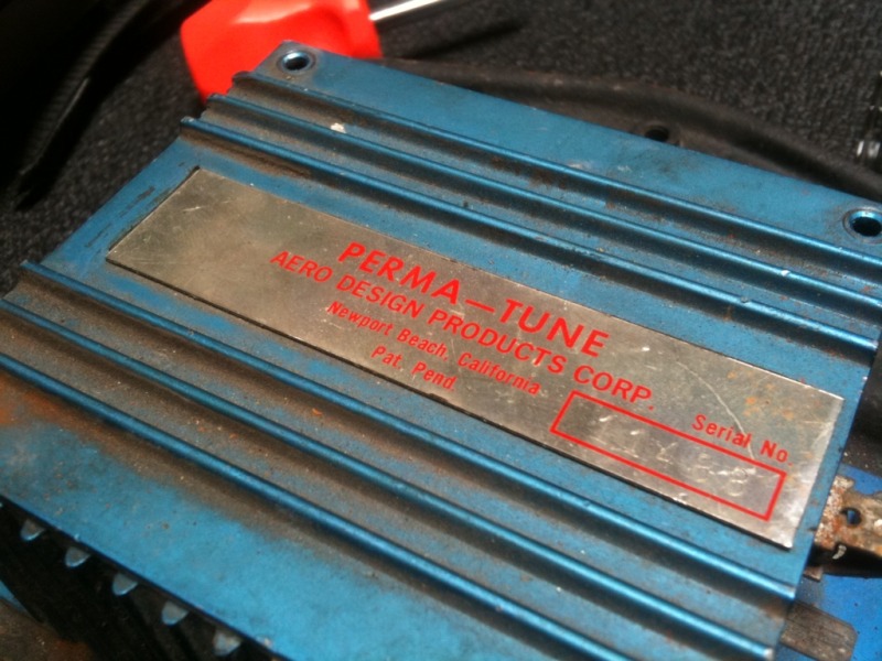
Hell, I'll trade you a Bosch unit for the "Permadoom"..... they're all the same to me.

But then I am not a professional mechanic .... just a backyard, shadetree parts changer ... huh.gif

Maybe the early Permadooms aren't that great ... I've run the silver one, blue one and I don't know if there are any other colors.
Eric_Shea
Please take a picture of your cousin holding the Permatune and the Bosch... then we can decide.
Eric_Shea
Slits... I will trade you a non working Bosch unit for a working one. (I know... generous. It's just the kinda guy I am) wink.gif
RiqueMar
QUOTE(Eric_Shea @ May 11 2011, 09:19 AM) *

Please take a picture of your cousin holding the Permatune and the Bosch... then we can decide.


Just as soon as you get your model to take a picture with the GT calipers you're going to 'donate' to my project! biggrin.gif
Eric_Shea
LOL... you can have Jeff's GT calipers that are in house. Pics to follow. biggrin.gif
PeeGreen 914
QUOTE(Eric_Shea @ May 11 2011, 03:26 PM) *

LOL... you can have Jeff's GT calipers that are in house. Pics to follow. biggrin.gif

drooley.gif
sixnotfour
QUOTE
LOL... you can have Jeff's GT calipers that are in house. Pics to follow.


Say What ????????

I have two red permatunes , what you all say about that ?
SLITS
QUOTE(sixnotfour @ May 11 2011, 03:40 PM) *

QUOTE
LOL... you can have Jeff's GT calipers that are in house. Pics to follow.


Say What ????????

I have two red permatunes , what you all say about that ?


Uhhhhh ..... they're Communist?

And Eric, I will trade you 3 non-working 3 pin CDI units + 2 non-working 6 pin units for one FACTORY PERIWINKLE CDI unit. No, you can't paint it 'cause I'll know. It has to be Factory Original.
RiqueMar
QUOTE(SLITS @ May 11 2011, 03:52 PM) *


Uhhhhh ..... they're Communist?


.... damn Commies...

Click to view attachment
RiqueMar
Ok, so all good on the wiring, just doing the alternator now. Problem is, I see no D+ confused24.gif

Also, there was many more connections when I disconnected this. From the thread Perry was referencing, it's my understanding that I should only have 3 wires from the relay board to the Alternator, is this correct?
SLITS
Yes .... tres, troi, drei, III, 3,

There is a ground strap, but it runs from one of the studs that holds the air guide to back of the alternator to the engine case.

RiqueMar
QUOTE(SLITS @ May 11 2011, 06:56 PM) *

Yes .... tres, troi, drei, III, 3,

There is a ground strap, but it runs from one of the studs that holds the air guide to back of the alternator to the engine case.


Ok, cool! So then I'm good!

The only thing I have left is to find which wire connects to the sender near the thermostat, the 'idiot light' and how to connect the blue wire to the number 2 position on the 14 pin connector.

I was reading this thread as well, and it was a bunch of help as well.... here
RiqueMar
This is basically where I'm at now, and I'm not sure how to include the blue wire into the pin 2 position of the 14-pin connector....

IPB Image
SLITS
The Red wire in your harness is already connected to pin 2 of the main harness thru the relay board traces. No need for the extra "blue" wire. Pin 2 of your main harness (14 pin connector) is the blue wire to the gauge lite. It run s from the relay board 14 pin connector thru the center tunnel and up behind the dash and connects to the lite with a diode inline.

Ok?

Now, if the blue wire is an extra, wire it to the oil pressure idiot lite via pin 1 on the 12 pin connector on the relay board. If you use a /4 engine harness, splice it into the green w/ red trace wire in the 12 pin connector. It again is automatically connected to pin 5 of the 14 pin main body harness connector which is green w/ red trace going to the oil idiot lite on the combo gauge.
Jeffs9146
Dont you also need to remove the Voltage Regulator?
SLITS
QUOTE(Jeffs9146 @ May 12 2011, 09:57 AM) *

Dont you also need to remove the Voltage Regulator?


No .... he is using an externally regulated alternator. The VR sits on pins in the relay board and is connected electrically by the traces underneath the goo on the back side of the relay board to the main harness for all the functions it needs.
RiqueMar
QUOTE(SLITS @ May 12 2011, 10:06 AM) *

QUOTE(Jeffs9146 @ May 12 2011, 09:57 AM) *

Dont you also need to remove the Voltage Regulator?


No .... he is using an externally regulated alternator. The VR sits on pins in the relay board and is connected electrically by the traces underneath the goo on the back side of the relay board to the main harness for all the functions it needs.


Thanks SLITS, that actually clarifies alot. I had seen the trace to pin two, but didnt know the red wire carried that signal as well. So there should only be 3 wires connected to the alternator.

It also answers my confusion about the Oil idiot light, I didnt realize it was spliced!
This is a "lo-fi" version of our main content. To view the full version with more information, formatting and images, please click here.
Invision Power Board © 2001-2024 Invision Power Services, Inc.