Hey All,
I swapped all of my bulbs for LEDs from Autolumination and/or
superbrightleds, and have encountered some unexpected issues. Replacing the
turn signal flasher was a known. I tried TimK's hack on the CF13 GL-02
flasher, and when installed and engaged, it just sat there, although the
hazard flashers worked fine (it seems to work on the same relay). I noticed
this aftermarket "LED" compatible relay design leaves out the "C" ground
pin, so I have a different one on order from Autolumination that has it.
When I raise my headlights, the tachometer dials up to 3-4K and then returns
to rest. My dash instrument lights have also been replaced with tiny LEDs
to match the originals, but they only flash once briefly when the light
switch is pulled. My blue high beam indicator is lit when the parking
lights are on, and my license plate lights never come on.
I picked up a 1974 color wiring diagram from Prospero's Garage (
http://stores.ebay.com/Prosperos-Wiring-Di...sid=p4340.l2563 ) and
noticed that many of the wires that connect to the computer are tied
together. I cut that part of the harness off and tied off all of those
wires individually (see image). I'm wondering if I need to reconnect some
of those wires to preserve the original circuit path.
<http://914electric.files.wordpress.com/2011/06/elect_danglies.jpg>
http://914electric.files.wordpress.com/201...ct_danglies.jpg
Does anybody have similar experiences? Also, is there a good source for the
factory color wiring diagram (Prospero's diagrams do not give terminal
designations for any switches - i.e. 56A, 56, C, 32, etc.).
Much thanks for any help.
(I was informed by Mikey at 914Rubber that there is another markb, so from
now on I will be:)
MCBrems
Full Version: LED Conversion - snafus?
I have used LEDs for all lights except the dash gauges without any problems.I did have a issue with the turn signals not functioning very well. I tried the LED compatible flasher unit with no luck, so I installed Superbrightled's load resistor (RL-650) on all four turn signal LED's and now they flash just like the stock lights. This is on a 73 2.0.
Full color factory wiring diagrams are available, for free, on the Pelican Parts website. www.pelicaparts.com
You'll have to do your own navigating when you get there, but it's pretty intuitive.
BTW, a number of the wires you cut and capped off are important to the operation of the car, and none of them are FI related.
Look at the diagram.
The Cap'n
You'll have to do your own navigating when you get there, but it's pretty intuitive.
BTW, a number of the wires you cut and capped off are important to the operation of the car, and none of them are FI related.
Look at the diagram.
The Cap'n
QUOTE
BTW, a number of the wires you cut and capped off are important to the operation of the car, and none of them are FI related.
Look at the diagram.
The Cap'n
Sorry - I wasn't clear that I am dumping the gas motor for an EV drive. Whoops.
Pelican offers only the current flow for the '74. I can make it work , but I was hoping for a wiring diagram.
What do you mean by "FI" ?
MCBrems
Fuel Injection.
Not applicable to your EV setup, of course.
--DD
Not applicable to your EV setup, of course.
--DD
This mantra is gonna become reality sometime. Or maybe not: Ask good questions, get good answers.
The Cap'n
The Cap'n
"Ask good questions, get good answers."
Here are the current flow diagrams. Couldn't find wiring diagrams for the '74.
http://www.pelicanparts.com/914/914_electrical_diagrams.htm
MCBrems
Here are the current flow diagrams. Couldn't find wiring diagrams for the '74.
http://www.pelicanparts.com/914/914_electrical_diagrams.htm
MCBrems
That's because Porsche didn't produce conventional wiring diagrams for cars after 1973 .........
Might find some in Mitchell On Demand, but they won't be in color.
The Cap'n
Might find some in Mitchell On Demand, but they won't be in color.
The Cap'n
Current flow diagrams ARE wiring diagrams. They are quite easy to read if you putt them all together. The legend on the left side talls you what the numbers are.
I only replaced the gauge illumination lights with LEDs and have no issues. What's the purpose in replacing turn signal, hand brake bulbs, etc? Perhaps I am missing something... which is very likely.
QUOTE(kg6dxn @ Jun 23 2011, 08:22 PM) 
Current flow diagrams ARE wiring diagrams. They are quite easy to read if you putt them all together. The legend on the left side talls you what the numbers are.
I agree wholeheartedly. Mine is a 73 but I frequently use the 74 diagrams because they are easier to follow.
Like the Capn said - there is more on the relay panel than just the fuel injection. I seem to remember that the Voltage Regulator has an influence up front some how. I think with an EV you are going to have to do a lot of planning for the entire electrical system. There have been a number of folks on this board that have done the EV conversion. Hopefully they will find this thread and add the benefit of their experience. Maybe put 'EV' in your title.
QUOTE(RickS @ Jun 23 2011, 09:40 PM)
I only replaced the gauge illumination lights with LEDs and have no issues. What's the purpose in replacing turn signal, hand brake bulbs, etc? Perhaps I am missing something... which is very likely.
Well, this is an EV conversion, and I want to minimize my power consumption as much as possible.
I think the issues I am seeing with the gauge illumination may have something to do with the dimmer on the parking/headlight switch. I was considering swapping all the bulbs back to incandescent for troubleshooting purposes.
Does the dimmer work for your gauge lighting?
MCBrems
QUOTE(Cap'n Krusty @ Jun 23 2011, 01:39 PM)
BTW, a number of the wires you cut and capped off are important to the operation of the car, and none of them are FI related.
Yeah - Looking at the diagram, a number of these wires are tied together on the relay panel, and I have isolated all of them (see image below).
http://914electric.files.wordpress.com/201...ct_danglies.jpg
My gut is telling me to at least reconnect the ones that are tied on the diagram.
MCB
Dang, your picture is big!! No wonder you couldn't upload it here...
Grey/brown are the reverse lights. Short those two together and the reverse lights should come on.
Fat red is always hot.
Brown is always always always ground. Always.
The fat yellow with a red stripe gets +12V when the key goes to "start".
Blue goes to the alternator warning light.
Black/purple is the tach signal wire.
Black/red is the coil power wire.
Green/red is the oil pressure light sender. (I think. Could be the oil temp sender wire, but I think that one is green/black.)
Not sure about the two solid green wires or the white wire. White is usually fuel injection related though.
--DD
Astounding! If I wash your feet with my tears, will I be upgraded from "newbie?"
I appreciate it, thanks!
I appreciate it, thanks!
Nope - not in the least. I have to have it on full illumination for them to work. Anything less and they will not work.
Does the dimmer work for your gauge lighting?
MCBrems
QUOTE
Does the dimmer work for your gauge lighting?
MCBrems
QUOTE(mcbrems @ Jun 23 2011, 04:19 PM)
"Ask good questions, get good answers."
Here are the current flow diagrams. Couldn't find wiring diagrams for the '74.
http://www.pelicanparts.com/914/914_electrical_diagrams.htm
MCBrems
Current flow is the best wiring diagram once you get used to it. Every circuit starts at the top with +12V and ends at the bottom with ground. And _EVERY_ detail is drawn.
With the early standard diagrams there are lots of confusing parallel runs and dead ends with numbers that go to a different page, and grounds just pop up wherever they want. The layout with everything positioned as it is in the car is nice, but ultimately just adds to the confusion.
If the RoadGlue forum ever gets put up here, there are lots of pics of my EV conversion process in the Alternate Power sub-forum. I'm still taking pics, but have no place to put them as yet. I have done a complete conversion to LEDs as well, and there are two gotchas:
1) The flasher relay (must be replaced with electronically timed version, which will not drive the dash turn signal bulb(s), or you must add load resistors). My solution used a GL-02 flasher, and for the dash turn signal bulbs involved adding a pair of arrow shaped LEDs to the trim plate, wired to the turn signal wires rather than the missing 4th pin on the flasher.
2) The headlight switch only runs the dash lights full brightness. LEDs can be dimmed, but simply cut off when using a simple rheostat like the headlight switch contains.
It sounds like you have mixed up some of the wiring on the gauges...
QUOTE(mcbrems @ Jun 24 2011, 09:37 AM)
Well, this is an EV conversion, and I want to minimize my power consumption as much as possible.
MCBrems
If you calculate the added range from replacing every bulb in the car with LED's you will find that you might actually gain on the order of 100's of feet of range over the incandescent bulbs, certainly not miles. I converted to LEDs for the look (added brightness IF you get the right bulbs) and the bragging rights, not for added range.
Headlights are the major draw, converting to HID ($$$) is currently the only lower-current alternative that are bright enough, IMO.
Indeed, I did convert to HID. I am still trying to locate a good lamp housing that replaces the standard H6024 7 inch stock sealed beam. There are so many choices out there. The one in my profile picture has developed a lens crack for unknown reasons, so I am replacing both (so they match). I haven't even powered the lamps up yet!
These conversion housings were made of a thick grey plastic, and I'm now wondering if I should switch to a metal reflector. I was told by HID Country that 35W HID bulbs are fine in the plastic housing, but the 55W bulbs may crack the lens. If the plastic serves as an insulator, then I'm concerned that a metal housing may cause my headlight cover paint to scorch. I'm also concerned about the plastic headlight shroud melting or warping.
Any advice or experience?
Thanks,
MCBrems
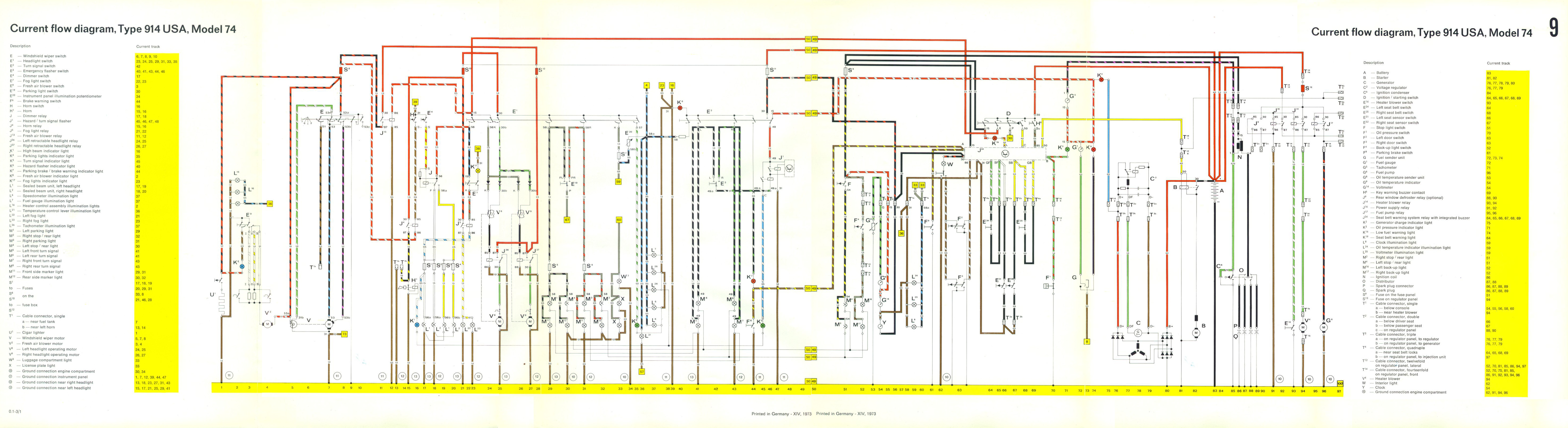
Here is a full composited color current flow diagram that I combined from all the sectional files on Pelican Part Tech forum:
http://www.pifflesquit.com/914_EV_Conversi...tric_74_ALL.jpg
Cheers,
MCBrems
http://www.pifflesquit.com/914_EV_Conversi...tric_74_ALL.jpg
Cheers,
MCBrems
QUOTE(Dave_Darling @ Jun 24 2011, 03:50 PM)
Dang, your picture is big!! No wonder you couldn't upload it here...
Grey/brown are the reverse lights. Short those two together and the reverse lights should come on.
Fat red is always hot.
Brown is always always always ground. Always.
The fat yellow with a red stripe gets +12V when the key goes to "start".
Blue goes to the alternator warning light.
Black/purple is the tach signal wire.
Black/red is the coil power wire.
Green/red is the oil pressure light sender. (I think. Could be the oil temp sender wire, but I think that one is green/black.)
Not sure about the two solid green wires or the white wire. White is usually fuel injection related though.
--DD
Resuscitating a year-old thread! I'm getting to the final stretch of my EV conversion, and am now spelunking into the wiring harness. This is what I discovered about the above:
There are two red primaries that are always hot, regardless of the key switch.
There is a black 12 gauge wire that is only hot when the key is on.
I thought for sure the coil wire (black/red) would also be hot when the key was on,
but it is not. That doesn't seem right.
I also expected at least the alternator warning light (blue) to also be hot when the key is on, but all wires are cold except for the black and two reds.
I will dig back into it tonight, with meter and wiring diagram in hand, but any thoughts here are welcome.
McB
The coil power wire looks a lot like the tach signal wire. The power wire is fatter than the signal wire, and goes on the other side of the coil.
I believe the blue alt light wire gets power any time the alt is charging.
--DD
I believe the blue alt light wire gets power any time the alt is charging.
--DD
I guess it makes sense that many of the wires I expected to be hot when the key is on - are not. The reason is the 2 red primaries coming directly from the battery are feeding the circuit board, which then decides where to send 12v when the ignition is on.
Looking over my diagram, I see you were correct about the blue wire. It is there to send 12v from the circuit board to the alternator light in the speedometer.
The coil wires are also run by the circuit board, and would be part of the engine harness, which I'm not using.
More digging to do.
McB
Looking over my diagram, I see you were correct about the blue wire. It is there to send 12v from the circuit board to the alternator light in the speedometer.
The coil wires are also run by the circuit board, and would be part of the engine harness, which I'm not using.
More digging to do.
McB
got any details about the conversion?
As a matter of fact, here is the blog address:
914electric.wordpress.com
Enjoy.

914electric.wordpress.com
Enjoy.
Very nice! Great research and fabrication. Looks like you are doing it up right! I'll follow with interest and no small degree of jealosy.
mcbrems - WOW; I checked out your site and though I do not desire an electric 914, I am seriously impressed by all of the fabrication and thought you have put into that car. It should be very cool and I am glad to see you have given a 914 a new lease on life. Congratulations.
Thanks! Hopefully, the car will be around for another 30 years (or longer).
QUOTE(mcbrems @ Jul 8 2011, 11:11 AM)
Here is a full composited color current flow diagram that I combined from all the sectional files on Pelican Part Tech forum:
http://www.pifflesquit.com/914_EV_Conversi...tric_74_ALL.jpg
Cheers,
MCBrems
PERFECT I was missing the key
If anyone is looking to replace gauge illumination bulbs with LED's, here's the ones I used:
Note that there are 4 different bulb holders in our gauges;
2 are body ground & 2 are separate wire ground.
2 different bulb base styles as well.
Barefoot
Click to view attachment
Click to view attachment
Note that there are 4 different bulb holders in our gauges;
2 are body ground & 2 are separate wire ground.
2 different bulb base styles as well.
Barefoot
Click to view attachment
Click to view attachment
This is a "lo-fi" version of our main content. To view the full version with more information, formatting and images, please click here.