McMark
Nov 12 2014, 12:30 PM
QUOTE(mr2by4 @ Nov 11 2014, 07:43 PM)

Mark,
How much does this sort of deluxe, COP, prewired EFI system cost?
Roughly $3000 for:
- New Custom Wiring Harness
- New Injectors
- New Ignition Coils (Coil-on-plug)
- New Throttle Position Sensor
- New MAP Sensor
- MicroSquirt v3
- Mounting and Blockoff Brackets
I'm sure there's a few more things I can't think of off the top of my head.
QUOTE(Vacca Rabite @ Nov 12 2014, 09:15 AM)
I did not hear the fuel pump turn on. But I was not listening for it either. I was only there for a few minutes. Long enough to plug in my laptop to see if there was communication.
If I can get time, I'll go back and run more tests, but I'm not sure tony would want me working on my car at his garage.
Zach
If the fuel pump isn't running, the MicroSquirt isn't turning on. PM me the Tony's number again and I'll call him.
peteyd
Mar 28 2015, 03:37 PM
Any updates on your car Zach?
You have this thing running and on the road?
Pete
VaccaRabite
Mar 30 2015, 07:46 PM
I need to call Tony tomorrow and find out. He said he'd have it running by the end of march.
Zach
Dr Evil
Mar 30 2015, 07:55 PM
r_towle
Mar 30 2015, 08:20 PM
QUOTE(Dr Evil @ Mar 30 2015, 09:55 PM)
What is that glass house throwing stones saying?
toon1
Mar 31 2015, 11:11 AM
QUOTE(Vacca Rabite @ Mar 30 2015, 06:46 PM)
I need to call Tony tomorrow and find out. He said he'd have it running by the end of march.
Zach
Whats wrong with it?
VaccaRabite
Mar 31 2015, 12:08 PM
Nothing in particular aside from me not having time to mess with it for the better part of 2 years. I gave it to Tony thinking it would be a summer project for his team. That turned into a year project. It's not like I'd suddenly have time to start working on it, so I have not made a fuss. When I get it it should be a dyno tuned system.
Zach
VaccaRabite
Mar 31 2015, 02:04 PM
I talked to Tony. Not running and he is stumped.
He can't get the ECU to connect to TunerStudio. Can't get to first base as it were. It's got power and ground but won't sync.
It did sync at one point. Lost connection in the middle of an operation and communication has not been able to be reestablished. I'm going over Friday to futz with it and could use whatever help I can get.
McMark
Mar 31 2015, 02:16 PM
Zach, will you confirm they tried the tips I sent them. If they did, I'm gonna drop a spare ECU in the mail for you. PM me their address. The ECU has a bad tach_out, but everything else works.
crash914
Mar 31 2015, 03:43 PM
Harness I think is different, but you are welcome to try my MSII to see if it works, we can swap the firmware easily....Marks solution is better, but anyway, mine is sitting here awaiting a car to put it in...oops, no vr circuit though...
McMark
Mar 31 2015, 03:53 PM
Yeah, MSII is very different. Nice offer though.

VaccaRabite
Mar 31 2015, 04:30 PM
Mark, when I talked with Tony today they said they had tried everything you had told them about.
Mail the ECU to me if you dont mind. If I cant get mine to connect this week, I'm going to pull it and send it to you to see if it works on an otherwise known good system.
Seriously thinking of towing my car back home. as long as I'm going to be working on it again, I'd rather walk out to my garage then take days off work to work at tony's shop. Nothing against Translog, but I just dont want them burning shop hours fighting a connection. I want them burning shop hours tuning.
Zach
VaccaRabite
Mar 31 2015, 04:33 PM
My plan of action thus far is to do a loopback test on the ECU. This will let me know if the laptop and ECU even see each other.
Then reload the firmware onto the ECU.
I'm putting together a checklist of parts and tests to run, since I will have limited time.
Going to bring full set of tools, and multimeter, and my laptop.
VaccaRabite
Apr 1 2015, 08:02 PM
Heading to Translog tomorrow. (thursday).
Packing up tools and I cant find my damn multimeter.
Guess I'll be stopping by the hardware store on the way there.
Zach
scotty b
Apr 1 2015, 08:07 PM
you realize you could have shipped the car to Mark
a year 3 years ago and be driving it right now don't you ?

r_towle
Apr 1 2015, 08:24 PM
QUOTE(scotty b @ Apr 1 2015, 10:07 PM)
you realize you could have shipped the car to Mark
a year 3 years ago and be driving it right now don't you ?
are you thinking about shipping your car to mark to get it done? Seems like a good plan Scotty, and we are supportive of you finally making the decision.
VaccaRabite
Apr 2 2015, 09:03 AM
Looks like the issue is a miswired factory serial cable!!!
I'm going out to find if I can buy a new minijack to DB9 cable.
On mine pin 2 is wired to pin 4. Only 2 pins used. Man I hope this is the issue!
ChrisFoley
Apr 2 2015, 10:10 AM
QUOTE(scotty b @ Apr 1 2015, 10:07 PM)
you realize you could have shipped the car to Mark
a year 3 years ago and be driving it right now don't you ?

Tangerine Racing is a whole lot closer.
I have Tunerstudio on my laptop and two customer cars at the shop running MS which we installed.
...just saying...
And no disrespect intended to McMark.

VaccaRabite
Apr 2 2015, 10:18 AM
QUOTE(Racer Chris @ Apr 2 2015, 11:10 AM)
QUOTE(scotty b @ Apr 1 2015, 10:07 PM)
you realize you could have shipped the car to Mark
a year 3 years ago and be driving it right now don't you ?
Tangerine Racing is a whole lot closer.
I have Tunerstudio on my laptop and two customer cars at the shop running MS which we installed.
...just saying...
And no disrespect intended to McMark.
Scott is starting rumors. :-/.
Car is not leaving York. I'm going to back the serial cable in a few minutes to fix the wireing. Then will see if it will connect. IF it does the car will start tuning at Translog.
Zach
scotty b
Apr 2 2015, 11:14 AM
QUOTE(Racer Chris @ Apr 2 2015, 08:10 AM)
QUOTE(scotty b @ Apr 1 2015, 10:07 PM)
you realize you could have shipped the car to Mark
a year 3 years ago and be driving it right now don't you ?
Tangerine Racing is a whole lot closer.
I have Tunerstudio on my laptop and two customer cars at the shop running MS which we installed.
...just saying...
And no disrespect intended to McMark.
No offense intended Chris. I was just busting Sach's sack by making an exaggerated point.
AndyB
Apr 2 2015, 11:22 AM
QUOTE(scotty b @ Apr 1 2015, 10:07 PM)
you realize you could have shipped the car to Mark
a year 3 years ago and be driving it right now don't you ?
Or you could of sent to CFR three years ago and driven it three years ago IMHO.
ChrisFoley
Apr 2 2015, 11:42 AM
QUOTE(scotty b @ Apr 2 2015, 01:14 PM)
No offense intended Chris. I was just busting Sach's sack by making an exaggerated point.
I know. I just wanted to throw in my $.02.

VaccaRabite
Apr 2 2015, 02:22 PM
Back at home again. Here is where I am at.
I hacked apart the DB9 end of the cable to "correct" the pin wiring. I have to say it in quotes as (after I hacked it up) I found other information that said it was correct the first time. But I get ahead of myself. I hacked up the cable, soldered the pins to the wires and tried to reinstall them into the DB9 head. This was not successful. The cable was never intended to be taken apart, and getting the pins back into the body resulted in mostly mangled pins. Then back to google to find information suggesting that the cable was right in the first place. *grumble*
At this point I packed up my stuff, grabbed the ECU out of my car and came home after doing a small favor for Tony by fixing a computer glitch he had on his office machine.
This was the pic that got me thinking my cable was wired wrong.
In this picture the wire that should have been on Pin 2 was on Pin 4.
HOWEVER
After I hacked the cable apart I found this:
WTF right?! Well I found the problem. The pic up top is of a MALE serial cable, and the pic below is of the FEMALE cable. I was just using google image search, and the pictures were not labeled as male/female. I had to figure that out on my own. My cable had the female end. Which means it was likely correct in the first place and I just ruined a okay cable.
So here is my plan.
buy a female 35 pin ampseal plug, new serial cable, and the Microsquirt mini-jack connector. With this I can bench test the ECU, and hopefully bring it up. At which point we can put it back in the car and start tuning.
I tested connectivity at the harness and its good. There may be a bad connection at the fuse block - I got a fault there unless I wiggled it around.
I also got more information on the failure mode in the first place. Tony said that they had connected to the ECU for a minute or two. The dashboard came up in tunerstudio, and the ECU was auto-detected. He turned around, and when he turned back connection had been lost.
Its not outside the realm of possibility that a bad connection at the fuse panel cut power to the ECU while it was connected to the laptop, corrupting the ECU. At this point I really don't know. I'm going to build the bench test rig and go from there.
I do have a JimStim which I may be able to wire into the bench test harness. That may be more trouble then its worth though. We shall see.
Zach
McMark
Apr 2 2015, 02:28 PM
Just left you a message Zach. Don't buy anything.
VaccaRabite
Apr 2 2015, 05:45 PM
So right now this is my plan for the test board.
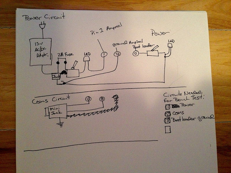
Please look and see if I have something glaring. Do I need to add a circuit?
I think I only need 3 circuits at this time.
1) Power
2) Coms
3) Bootloader Ground
I have a 15 volt, 1.4 amp power AC to DC power converter on hand. This will allow me to plug the test box into a wall and not have to fiddle with batteries.
The numbers inside circles are the pins to the Ampseal jack.
Boot loader will be on a switch instead of plugging and unplugging a wire, with an LED to show when it is grounding.
Zach
VaccaRabite
Apr 2 2015, 07:10 PM
On a whim, as there is little else I can do right now, I just checked continuity on the ECU. I got no connection between pin 1 (power) and pins 19-23 (all ground pins).
Should I have continuity between Power and Ground pins while no power is applied to the ECU?
Zach
McMark
Apr 2 2015, 08:06 PM
I don't know for sure, can't test till Saturday. But I'm doubtful. There shouldn't be a clean path from power to ground because that would be a dead short. It's also unlikely there are any resistor type connections from power to ground. Most of the stuff is IC and does things with the power only when it's on.
r_towle
Apr 2 2015, 08:08 PM
QUOTE(Vacca Rabite @ Apr 2 2015, 09:10 PM)
On a whim, as there is little else I can do right now, I just checked continuity on the ECU. I got no connection between pin 1 (power) and pins 19-23 (all ground pins).
Should I have continuity between Power and Ground pins while no power is applied to the ECU?
Zach
no
You might want tp bend Mark Skalas ear on testing this....he may be of help...
I recall he is a hardware guy.
Rich
VaccaRabite
Apr 2 2015, 08:17 PM
QUOTE(McMark @ Apr 2 2015, 09:06 PM)
I don't know for sure, can't test till Saturday. But I'm doubtful. There shouldn't be a clean path from power to ground because that would be a dead short. It's also unlikely there are any resistor type connections from power to ground. Most of the stuff is IC and does things with the power only when it's on.
QUOTE(r_towle @ Apr 2 2015, 09:06 PM)
no
You might want tp bend Mark Skalas ear on testing this....he may be of help...
I recall he is a hardware guy.
Rich
I suspected as much. Thanks guys.
Zach
okieflyr
Apr 3 2015, 05:46 AM
Some power converters do not produce a clean enough voltage signal that sensitive electronics require.
A dedicated power supply may be better for the job if you can get your hands on one.
Spoke
Apr 3 2015, 06:38 AM
QUOTE(Vacca Rabite @ Apr 2 2015, 07:45 PM)
So right now this is my plan for the test board.
Please look and see if I have something glaring. Do I need to add a circuit?
I think I only need 3 circuits at this time.
1) Power
2) Coms
3) Bootloader Ground
I have a 15 volt, 1.4 amp power AC to DC power converter on hand. This will allow me to plug the test box into a wall and not have to fiddle with batteries.
The numbers inside circles are the pins to the Ampseal jack.
Boot loader will be on a switch instead of plugging and unplugging a wire, with an LED to show when it is grounding.
Zach
If pin 1 is the power pin, the LED should not be in series with it unless the manufacturer says so. If you want an LED to let you know when power is on, the LED should be connected between the switched power and ground through a resistor of about 5-10k ohms.
A couple of things from previous posts: You 'may' be able to see some resistance from power to ground with the power off. If it was a dead short, it would show up as zero ohms. This is not a conclusive test.
About the power supply noise, chances are the automotive voltage rails are about as noisy as can be. The electronics in the MS run off a low voltage like 5V or 3.3V or lower and likely have significant filtering from the input power to the conditioned digital power.
Still a good idea to have as quiet a power supply as possible. If you're going to have a fuse in the path, why not use a car battery? The load on the battery has to be minor and should give hours of running just the MS.
VaccaRabite
Apr 3 2015, 06:43 AM
I don't have a spare car battery. My 914 and its battery are at Tony's shop.
Spoke
Apr 3 2015, 07:12 AM
Your power supply should be ok.
What exactly happened that the MS stopped working? I read through your thread but couldn't tell when the ECU stopped working.
I'll offer to take a look at it and see what's wrong. We do electronic solution development at work and have a lot of experience with small systems like MS.
Here's one we just finished. It's a camera on a needle for probing knees and shoulders. Pretty cool. We did the camera board (me) and the base processor and software. It runs Android.
 Trice Medical Mi-Eye
crash914
Apr 3 2015, 08:06 AM
crash914
Apr 3 2015, 08:06 AM
it could be just the rs232 chip that is no good....
McMark
Apr 3 2015, 08:38 AM
Careful of changes by version. That schematic is v2.2, the ECU is v3.
crash914
Apr 3 2015, 08:40 AM
yea, i thought about that.....ver 3.0 is also available...
VaccaRabite
Apr 3 2015, 09:12 AM
QUOTE(Spoke @ Apr 3 2015, 08:12 AM)
Your power supply should be ok.
What exactly happened that the MS stopped working? I read through your thread but couldn't tell when the ECU stopped working.
I'll offer to take a look at it and see what's wrong. We do electronic solution development at work and have a lot of experience with small systems like MS.
Here's one we just finished. It's a camera on a needle for probing knees and shoulders. Pretty cool. We did the camera board (me) and the base processor and software. It runs Android.
Trice Medical Mi-EyeI don't know. I was not there. All I know is what was stated. They had it connected, ad then it stopped communicating.
Could I get you to draw out the circuit (so a dummy layman like me could build it) so that I can have the LEDs light up when there is power to their circuit?
Zach
Spoke
Apr 3 2015, 10:29 AM
QUOTE(crash914 @ Apr 3 2015, 10:06 AM)
Thanks but the link just takes me to a logo.gif file. I looked on the MS website but still didn't find the schematic. Got another link to the schematic?
Spoke
Apr 3 2015, 10:43 AM
QUOTE(Vacca Rabite @ Apr 3 2015, 11:12 AM)
Could I get you to draw out the circuit (so a dummy layman like me could build it) so that I can have the LEDs light up when there is power to their circuit?
Zach
Here's the main part of the circuit. The LED with the bootloader is not in the right place but I don't have a schematic to add this to it.
When you connect the power from the wall wart, do not connect the MS to it yet. Connect the fuse, switch, LED and resistor and try the power. If the LED doesn't light when you close the switch, the voltage is backwards. If the LED lights when the switch is closed, then the power is correct. Then turn the switch off and connect the MS.
When you're done with this and it doesn't work, you can give it to me and perhaps I can get it running and give it to you at Hershey. BTW, I pass through Harrisburg 2 times a week if you want to drop it off.
McMark
Apr 3 2015, 12:07 PM
QUOTE(Vacca Rabite @ Apr 3 2015, 05:43 AM)
I don't have a spare car battery. My 914 and its battery are at Tony's shop.
Motorcycle batteries are pretty cheap and make great tester batteries for all sorts of automotive projects.

crash914
Apr 3 2015, 05:07 PM
Let's try this one.
Never mind......can't cut and paste
VaccaRabite
Apr 3 2015, 05:55 PM
Herb, i may come to pick your brain when I get the tester built. Youve done this before and that may come inhandy trying to get the ECU back on line.
Zach
crash914
Apr 3 2015, 06:14 PM
No problem...Jim stim and unit on my bench. I think I have everything to fab a cable if needed...
VaccaRabite
Apr 9 2015, 07:16 PM
Well, I built the breadboard for the power circuit, and found an issue.
My 15 volt power supply (which would have been perfect for this) is actually a 20 volt power supply. Glad I checked it with a multimeter before connecting the MS unit.
Microsquirt can take a 9V to 17v supply. Looks like its time to go get a lawn tractor battery. At least I'll have a hot spare when the battery on my tractor dies.
Zach
VaccaRabite
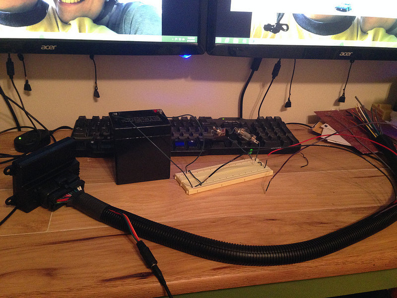
Apr 11 2015, 09:18 PM
Tester for power built.
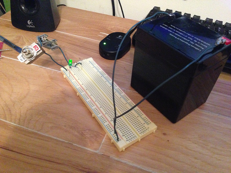
tested with the meter: 12.68 volts. In business.
Attach the leads and put 12 volts on the Microsquirt controller. No problem.
Turn that off, and go to hook up laptop.
Zach
VaccaRabite
Apr 11 2015, 09:34 PM
My laptop has sucessfully communicated with Microsquirt!!!!!!!!
WOOOO!
Now I just need to figure out why it won't on my car... My laptop detected the microsquirt ecu within second of plugging it in, so I know the ECU is good. I also know my laptop is good.
Harness? Ground loop?
zach
VaccaRabite
Apr 11 2015, 09:54 PM
So here is my theory.
This test circuit only has power and ground and communications. Nothing else is hooked up.
I recall in the startup file I was reading again last night it said to unhook all the sensor leads and make sure they are not grounding anywhere. I bet this is the issue. The leads are unplugged but were just laying in the engine bay. I bet they are grounding and creating some sort of connection problem.
The other possibility is a fault in the harness. Maybe a bad crimp somewhere. Though I tested continuity on the harness and I got a solid tone each time, so this is not a strong theory.
Wont know till I can get back to the 914, which may have to wait till after Hershey - depending on Tony's schedule.
Zach
VaccaRabite
Apr 14 2015, 10:21 AM
Brain goes back in the catr on Thursday for further testing. I had taken thursday off for Hershey anyhow, so this will be good timing.
Still, excited that I was able to get my laptop to talk to it, eleminating the ECU and my laptop as the issue.
Zach
VaccaRabite
Apr 16 2015, 10:47 AM
No dice. Once in the car the ECU failed to connect again. I pulled everything that could be causing a ground loop out, still no love.
Finally pulled the wire harness to bench test at home. I may do this tonight at the Knights Inn, since the whole mess is in my car already.
Stuff I tested: there is power for sure. 12 volts.
Grounds are clean. Grounds go from the engine block to 1 place on the engine harness - so we should be getting a clean ground to the ECU.
The harness is the only thing I can think of at this point that would be causing a problem. Hopefully I will be able to figure that out tonight or tomorrow.
Zach
This is a "lo-fi" version of our main content. To view the full version with more information, formatting and images, please
click here.

