Didn't get to work on the 914 as much as I hoped over my vacation, but still made some good progress over the last couple of days...
Frame rails in the engine comp. are stripped naked
They still need some minor detailing here and there and the "hell holes" still need to be cleaned, but most of the hard work is done
Tonight I welded the rear shock towers to the frame rails
Quite a gap to fill...
Full Version: Frame rails...
Welded up...

Top of the drivers side still needs to be welded, will do that later this week
Oh, the rust brown is just grinding dust. It's only visible in the pics
Oh, the rust brown is just grinding dust. It's only visible in the pics
Last pic for now...
I wanted to buy a better welding machine, but we also needed a new couch for the living room
I wanted to buy a better welding machine, but we also needed a new couch for the living room
Damn, the trunk is GONE and the engine shelf...
Looking good....
Looking good....
Gotta have room for that 917 motor! 
Good lookin work Jeroen.
Good job Charlie Brown 
Perfect pic to show people WHY our cars split the outer frame rail in the inner fender. I have a hard time explaining to people that the frame rails end in front of the shock tower. This will make life much easier. Thanks for the pics.
B
Perfect pic to show people WHY our cars split the outer frame rail in the inner fender. I have a hard time explaining to people that the frame rails end in front of the shock tower. This will make life much easier. Thanks for the pics.
B
Wow, I never realized how those towers are attached to the frame rails. Thank you for the pictures. Brad, Now i know what you were talking about in one of the previous threads. You were explaining about the weak area's and how some of the frame stiffening kits don't really address the problems. Good stuff 
You got it.
The GT stiff kit pieces that go inside the fenderwell are worthless. They weld onto a cover for the frame rail. Cut the cover off and install the stiff kit... then it would actually do something. You have to tie the frame rail to the shock tower better than the factory did. These pics show how the frame rail is only attached on front side of the shock tower. Over time the shock tower tries to rip away from the frame rail (Jeroen listened and welded it all up)
B
Is there a way to do this without cutting out part of the trunk? Also, do you have to take the engine out to do this?
Damn.. nice job Jeroen.
I plagerized some of your ideas from the past and recently just got my car back from paint with the same seam welding...
I cut our access hole with a plasma torch to this same seam... welded it, and then welded in a bracket that tied the two parts together. I was able to put the cover back on and weld it closed again... ground down the welds and had the paint shot, so that you can barely even tell that cavity was opened up...
wish I had a digital camera (again)
brant
Damn day lae and a dollar short. Wish I would have seen this before I did all my welding of the hell hole.
You know while you are in there stuff.
You know while you are in there stuff.
I confused 
w/o seeing the original back eng. wall in place Im not understanding.
Are you saying the seam shown as unwelded in the first pic (rail to tower ) is how the factory left it? No spots nuthin?
w/o seeing the original back eng. wall in place Im not understanding.
Are you saying the seam shown as unwelded in the first pic (rail to tower ) is how the factory left it? No spots nuthin?
It has small tabs that are folded over and spot welded to the front of the shock tower.
B
B
Maybe this pic helps you get a better idea...
Here you can also clearly see that the firewall is actually double walled
(hence, no need for one of those rear shock braces that you see sometimes)
Here you can also clearly see that the firewall is actually double walled
(hence, no need for one of those rear shock braces that you see sometimes)
I'm going to revive this thread from August.
I looked at a bare tub today and it looks as though the longitudinal is spot welded to the shock tower along that seam that is clearly visable in Jeroen's 1st picture. It looks as though it is spot welded from the inside. I was able to look up into the shock tower and see spot welds where the longitudinal would terminate.
Question 1:
Is this correct? Has anyone seen inside the longitudinal at this point? Brad? Brandt? Jeroen?
Question 2:
That being the case, are you seam welding this area for strength?
Question 3:
That not being the case, did the factory forget to weld the longitudinal to the shock tower in this area?
Question 4:
Brandt, any further info on your procedure?
Thanks in advance!
E.
Eric,
1) Actually I have not looked inside a longitudinal at this point... I've looked at it from the outside (both the inboard and out board outsides)
2) Yep.. that was my intent. Seam welding for strength.
The tube frame cars all run the roll cage to the top of the shock tower for the same reason. The top of the shock tower wants to pull up from the longitudinal and shears the factory spot welds...
3) I think the factory spot welded it a little bit, but with the BIG high rate springs the race cars use these days the factorys welds are not adequate.
4) I just seam welded the inside (from within the spring tower cavity) and then opened up the cavity on the engine side and seam welded the outside from there....
I'm not allowed to run my roll cage to the suspension points.. thus the reason I tried it this way.
Also, I think my one picture on my thread that shows the seam welding inside the tower... That picture only shows one half of the inside, and I went all the way around on the inside (but didn't get a good picture of it...)
brant
 Please? This is for my tub.
Hey Eric,
Brant posted this in his thread:
QUOTE(brant Posted on Nov 16 2004 @ 08:22 AM)
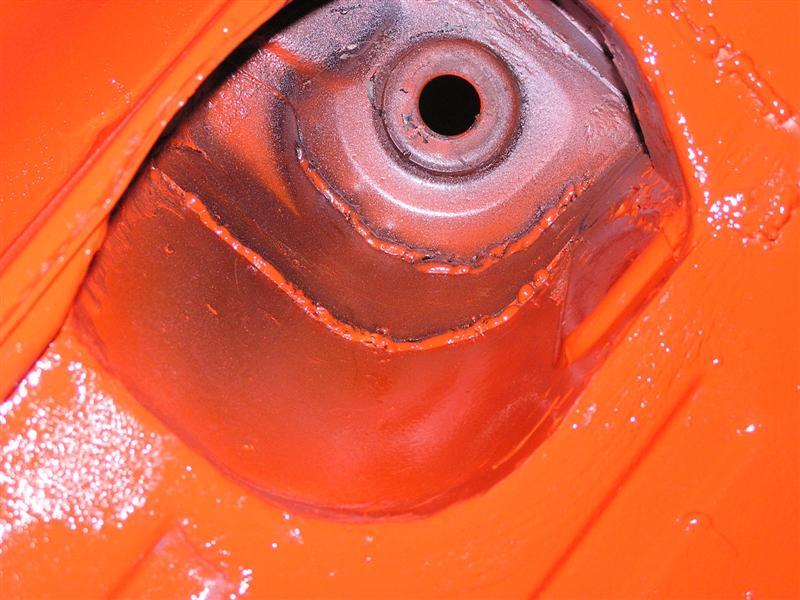
Jeroen,
this one is for you.
I mentioned this previously, but I used a plasma cutter to open the frame cavity and do some welding inside to brace the rear towers..... Then closed it back up.
You can see my welding seam.. Its kinda a big triangle (about 6inches long):
this one is for you.
I mentioned this previously, but I used a plasma cutter to open the frame cavity and do some welding inside to brace the rear towers..... Then closed it back up.
You can see my welding seam.. Its kinda a big triangle (about 6inches long):
Here is the other picture Brant referred to of the inside of the shock tower.
QUOTE(brant Posted: Nov 1 2004 @ 09:18 PM)
Here is the seam welding on the rear towers inside..
Jeroen, I mentioned this once a while back... I don't have to tell you not to over look this area. 1/2 of the rear seams are inside. You can't see them due to all the body filler the factory puts in there. you can grind that crud out with a wire wheel and then get to them.
I don't have a pic of it, but I also cut open to access the frame end in the engine bay. Right where it butts up to this tower. We welded that and then closed the access portal back up.. Welded it closed and you can barely tell after a bit of grinding
here she is from beneath:
Thanks Brant!
Don't stop there.
Jeroen, interested in hearing your perspective on this as well. In fact anyone who has been in this area, please let us know your thoughts about strengthening it.
Don't stop there.
Jeroen, interested in hearing your perspective on this as well. In fact anyone who has been in this area, please let us know your thoughts about strengthening it.
Mike,
one more thing and then I'll shut up and let Jeroen and others reply....
I don't think that you have too worry tooo much about this area on a street car.
Brad always used to say it was only problematic on cars with around 300# springs...
I talked to AJ, and he kinda reinforced Brads statements.
AJ said that on the HUGE tube frame cars (with Downforce) they have to run Big springs (due to the downforce) and so they go ahead and reinforce those cars....
What I'm trying to say is that on a street car its not a common failure.
brant
I hear ya, but if I want to do it, now is the time.
I don't baby my cars.
This car will see the track, even if it isn't much for the first few years.
It will get Mueller bearings which may necessitate stiffer springs.
It may also get much more motor and some point in the future.
And it could very well see significant track time after the shine of the resto wears a bit.
Me agrees with Brandt.
Here's what we (Mike and I) discussed over the phone:
I thouhgt the longitudinal was spot welded there. A visual inspection of the tub kinda bears that out. As a "while we're in there" philosophy for a street 914-6 that might get driven hard, I thought that seam welding all the factory GT points like what Brandt has done (both inside and out of the shock tower) would be good. I also thought that one who knows how to weld very well could lay a bead down that line inside the rear shock tower where the longitudinal meets. With proper penetration of the weld it would make it stronger. You can see the spot weld so you can follow the joint, effectively seam welding from the backside.
Either that or not worry about that seam and seam weld all those other areas previously discussed.
Thoughts?
I know I said that I'd shut up, but oh well.....
my thoughts:
-probably not totally necessary
-better bearings should acually reduce the effective spring rate...
but if it was mine, I'd do a little bit of it since your there and it hasn't been painted yet.
brant
my thoughts:
-probably not totally necessary
-better bearings should acually reduce the effective spring rate...
but if it was mine, I'd do a little bit of it since your there and it hasn't been painted yet.
brant
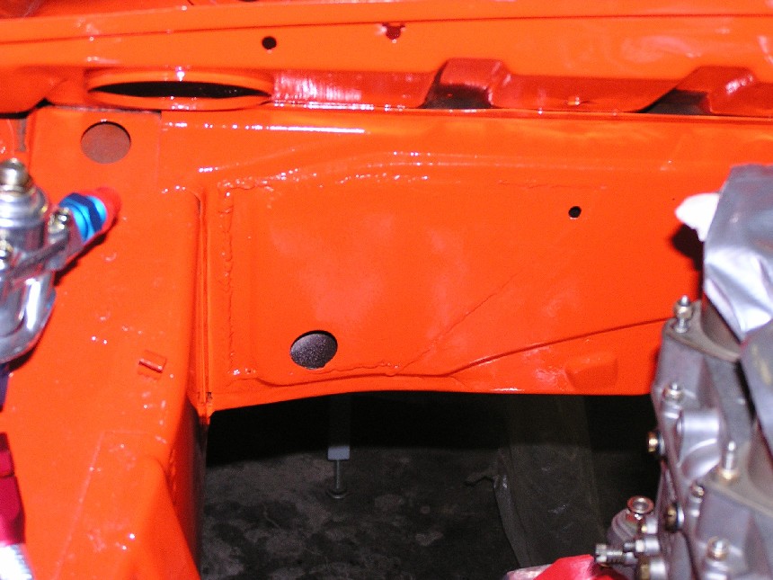
Ok, I'll try and explain best as I can...
In the pic below, the sheetmetal plate marked "A" is basically the outside of the engine bay/reartrunk firewall. With outside, I mean the part that you look at when viewing from the rear trunk.
This piece runs from inner fenderwell to inner fenderwell.
At the seam marked "B" you can see how part "A" bends inward toward the rear window.
It sorta bends over the top of the long and is spotwelded there.
These spotwelds can be seen if you remove the seamsealer around the shock tower.
At the seam marked "C" the long has a small lip (aprox 1/4") that is folded to the inside of the long. This lip is spotwelded to part "A" from the outside (shocktower side).
They must have done that before the shocktower was welded in place.
So basically, part "A" is welded in between the shocktower and the long.
The seamweld I made on top, directly welds the long to the shocktower (because I grinded part A flush there)
Hope this makes sense... If not, shoot some more questions
If you wanna keep the firewall in place, like Brant. Doing what he did is a very good option.
In addition (I'm not sure if Brant did this) you can do some extra seamwelds on seam "B"
Seamweld part "A" to the long (from the engine bay) and seamweld part "A" to the top of the shocktower (from the rear trunk)
By doing so, you basically seamweld the top of the long to the top of the shocktower
In addition (I'm not sure if Brant did this) you can do some extra seamwelds on seam "B"
Seamweld part "A" to the long (from the engine bay) and seamweld part "A" to the top of the shocktower (from the rear trunk)
By doing so, you basically seamweld the top of the long to the top of the shocktower
So you are referring to all of the area highlighted in yellow plus an area that can't be seen in the picture, which would be just below the letter D, right.
Jeroen,
Isn't the sheet metal on the shock tower a heavier (thicker) gage than other areas?
It seems like it when I tap on it (I know, not real scienific)
Paul
Isn't the sheet metal on the shock tower a heavier (thicker) gage than other areas?
It seems like it when I tap on it (I know, not real scienific)
Paul
I'm going to cut my firewall out. and I'm going to cut the sheetmetal out that the tranny mounts to. I'm gonna run 1" tubing from the shock towers down to hold the rear od the tranny. 
Paul
Paul
QUOTE(Jeroen Posted on Nov 16 2004 @ 05:32 PM)
Ok, I'll try and explain best as I can...
Thanks my friend. I think we have the info we need now.
One more picture and commentary from another of Jeroen's threads. Just for completeness. This picture will help those like me who originally had trouble envisioning all of this without an actual 914 in the garage to look at. The cutaway of the firewall was especially helpful I thought.
I think this entire thread is a pretty good pictorial and description of the issue.
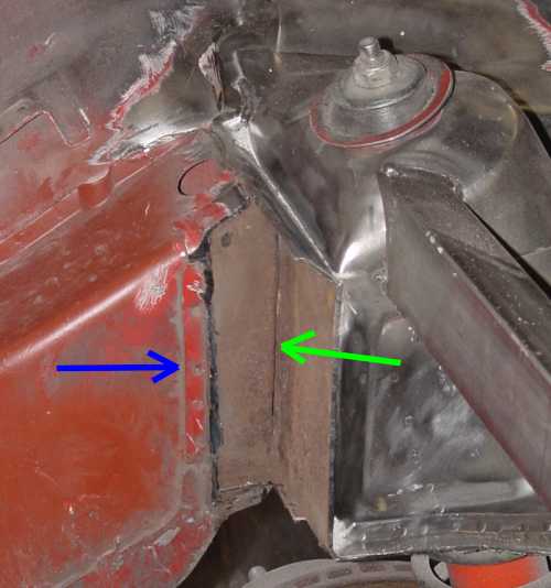
QUOTE(Jeroen Posted on Oct 11 2003 @ 08:43 AM)
It's because the crappy connection from the framerails to the shock towers
Look at the picture below... the firewall has been cut out and shows the crappy connection from the framerails to the shock towers (green arrow)
The spotwelded seam from the firewall (blue arrow) is supposed to take care of all the stress... and like you noticed, it won't do a very good job at that...
QUOTE(URY914 @ Nov 17 2004, 03:16 AM)
Isn't the sheet metal on the shock tower a heavier (thicker) gage than other areas?
Not as far as I know. I believe that all the sheetmetal on the car is the same gauge
I have a cool pic of a disected (sp?) shocktower on my home computer.
It shows just how amazingly complex the 914 is
I'll post it when I get home.
QUOTE(hargray2 @ Nov 17 2004, 03:11 AM)
So you are referring to all of the area highlighted in yellow plus an area that can't be seen in the picture, which would be just below the letter D, right.
Daniel,
The weak spot is seam "B" and "C"
Some aditional welding round the shocktower wouldn't hurt of course...
I think a fully dissected set of views would be really helpful. Something to think about at the next sawzall party. Mark up all the pieces the factory used and kind of sequence the build process. Part B is spot welded to Part A along seam X. That would help us visualize the strengths and weaknesses of the construction. Then we can determine various fixes for street, track and race cars. Knowing where all the cavities are helps. I imagine the design engineers had a lot of fun trying to figure out how to build these cars.
Here's the disected shocktower pic
This is just on example of how complex the bodystructure of the 914 is
It's just a briliant piece of design, even to today's standards
Then imagine the figured this out in the late sixties. No fancy CAD computers, nothing but a piece of paper and a pencil
When you're at a resto shop, you should take a look at some other cars of similar vintage. They're a joke compared to the ingenuity of the 914
I should have some more pics like this, I'll do a search...
(I can't take credit for this pic)
That is a great shot.
Some sawzall pics, courtesy of Mike Mueller
Driver side shocktower
Driver side shocktower
drivers side front shoch tower
drivers side front shock tower - close up
firewall (passenger/engine)
rear trunk, x-section of the dogbone, near the tranny mount
last one...
Targa/roll bar inner reinforcement
Targa/roll bar inner reinforcement
QUOTE
At the seam marked "C" the long has a small lip (aprox 1/4") that is folded to the inside of the long. This lip is spotwelded to part "A" from the outside (shocktower side). They must have done that before the shocktower was welded in place.
OK... That's the answer I was looking for. It is welded, just not very well. Thanks.
I've looked at Gint's tub again this morning. Here's some things I'll throw out there as was my discussion with Gint a few hours ago:
1. Brad is right. (first time for everything
 ). The factory stiffening kit gets welded to a cover plate not to the actual longitudinal and shock tower area. This is an area of sheet metal that is pressed into the inner fender well and it sticks up about 1/8" to 1/4" depending upon the area. Those who have been there know what I'm talking about.
After looking at that area, I believe there is a fix for this that will make the factory kit "VERY" useful. That fix is this:
Tack weld the ends of the factory piece or use clamps to hold it in place (this is the long piece that ties the longitudinal into the shock tower). It is drilled rosette. With the appropriate drill, drill out all the rosettes in the "outer layer" that Brad talks about. Next, rosette weld through both pieces to the actual longitudinal and shock tower.
2. I'm not sold on the need for seam welding the shock towers. After looking at this car and Jeroen's recent photo I believe the factory was simply chasing after whatever they thought might solve their problem. The seam in the shock tower has "2 rows" of spot welds and we've never seen one split there.
I do believe that Brad, Jeroen whomever "did" find the problem area and I think we've found another way to strengthen it "IF" you so care to do so without the surgery seen here (not that that's bad... just that some application would probably forbid this method). This is it...
3. Using a die grinder and a burr from the "inside" of the shock tower that seam can be accessed (seam marked C). A bead can then be applied from the backside and closed upon itself all within the shock tower.
So...
The factory kit can be made to work (I think, and so does Troy who would be doing the welding). I really think that a factory kit installed this way (weld the rosettes through to the actual longitudinal and shock tower) would do away with the need for most of this welding and reinforcing.
Seam welding the shocktowers looks like it wouldn’t be that effective based upon the massive amounts of spot welds there.
Most of the elusive "seam marked C" can be welded from the inside of the shocktower if you have a stockish vehicle and want to preserve the cosmetic integrity while strengthening that area.
Thoughts?
Thanks Eric...
Great pics guys! 'Saved' them all!!
I had no idea that there were that many double-walled areas on our cars.......looks like I'll be needing another gallon of Ospho!
I had no idea that there were that many double-walled areas on our cars.......looks like I'll be needing another gallon of Ospho!
Anybody have any pics of the shock tower seperated or damaged?
QUOTE(Eric_Shea @ Nov 17 2004, 12:32 PM)
rosette weld through both pieces to the actual longitudinal and shock tower.
This is what I've had in mind for a while.
Ok, maybe this is more clear
The pic below shows how I think it is best to weld "seam B" if you leave the firewall in place
Weld a bead from each side of the firewall over the width of the long
To get to "seam C" it's best to do it the way Brant did
Cut a small section of the inner wall of the firewall (inner = looking from the engine bay)
Weld up "seam C" and close the firewall back up
Guys,
Something to keep in mind. Seam welding can actually make a part weaker by creating a stress point along the line of the weld. You are much better off running small short "plug" welds. These would be about 1-2 inches in length seperated by the same length. This will be much stronger.
Something to keep in mind. Seam welding can actually make a part weaker by creating a stress point along the line of the weld. You are much better off running small short "plug" welds. These would be about 1-2 inches in length seperated by the same length. This will be much stronger.
QUOTE
To get to "seam C" it's best to do it the way Brant did
Why?
I'm asking because I was told by an "very" experienced fabricator that it's 6's at that point, meaning a toss up. That rear firewall piece "is" your rear shock tower brace and an intrigal part of the backbone of the car as you have pointed out. By cutting it with a torch and then rewelding it you fatigue and harden the metal.
He also said "exactly" what Brett just said about the seam welding. Same thing goes there. With literally dozens of welds (double spot rows) on the shock towers he looked at me like I was crazy when I said we wanted to seam weld there (sorry Brandt, not panning on your ride... it's absolutely beautiful. Actually, it's buttfuckingugly and I hate your guts! Had to have a reason for Miles to chime in here
).Jeroen, I like your idea about the welds into the seams at the back of the shock tower. I wondered about that area myself.
If there is a real reason that "it's best" to do it that way, please let us know now because Gint's tub is going into paint in the next week or two. Gint, correct me if I'm wrong here but this is a street car that will be driven hard at a couple DE events per year. I'm guessing it will get "spirited" driving on the street as well (based on the way you abused my poor little car with me right there in the passengers seat!
).Thanks!
E.
Remove the cover. Weld stiff kit to frame rail. Weld cover back on. This also leaves you more room for TIRE. I hate seeing comp cars with the kit installed and the tires rubbing the stiff kit. It ads material and takes away space if you do it the way the factory did.
B
B
This is a "lo-fi" version of our main content. To view the full version with more information, formatting and images, please click here.