Hey, awesome stuff. If you are OK with it, I am going to toss in some other info for others who might use this as a guide in the future. I don't think I am saying anything counter to what you are doing.

QUOTE(mrbubblehead @ Mar 14 2013, 02:45 PM)

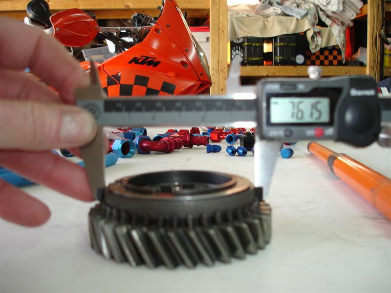
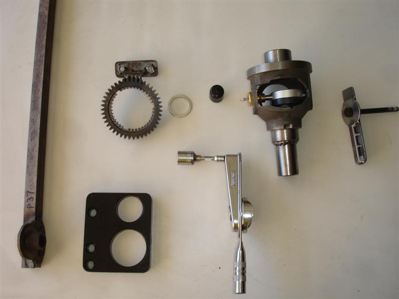
...here they are top left to right. P37, P259, P357, P258, P259
bottom left to right. P260, back lash torque wrench
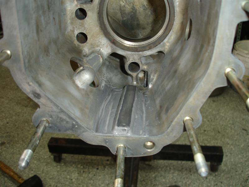
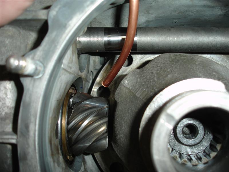
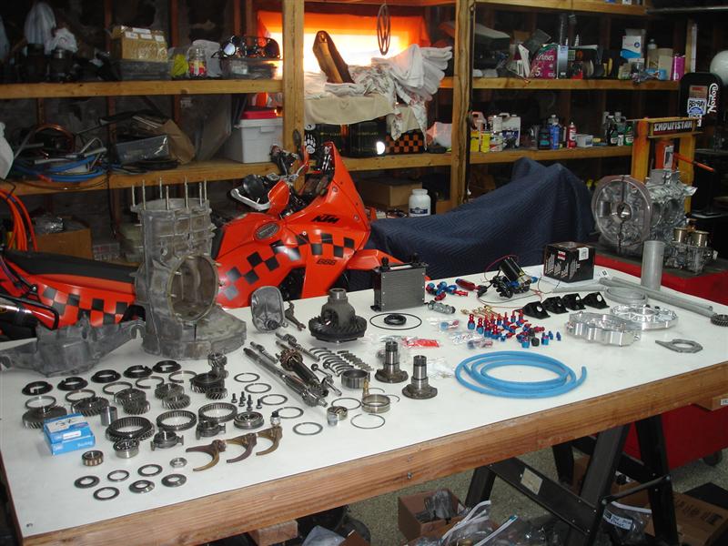
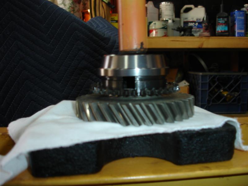
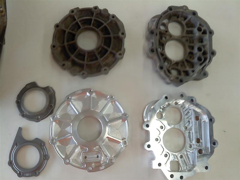
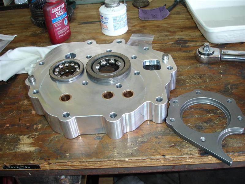
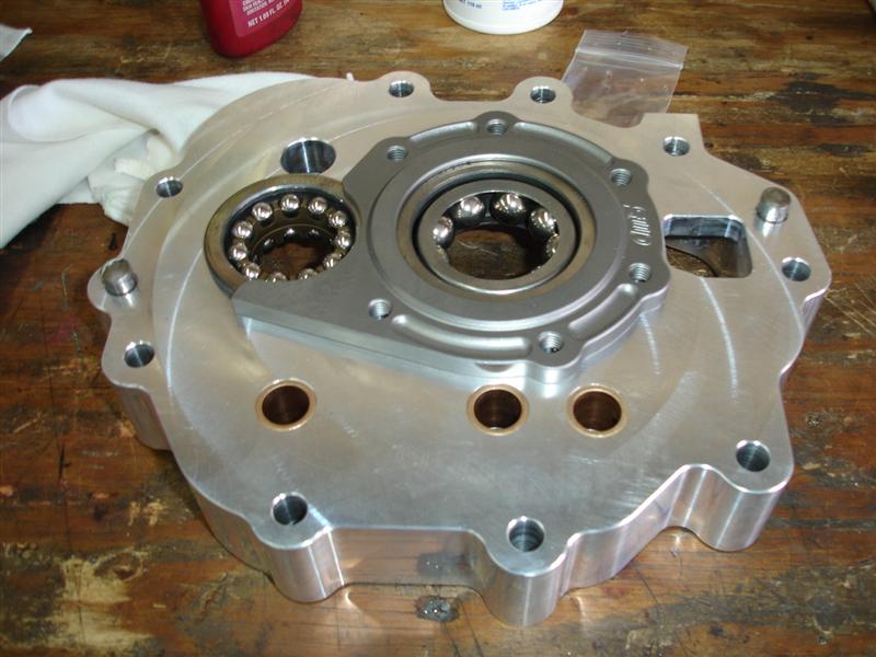
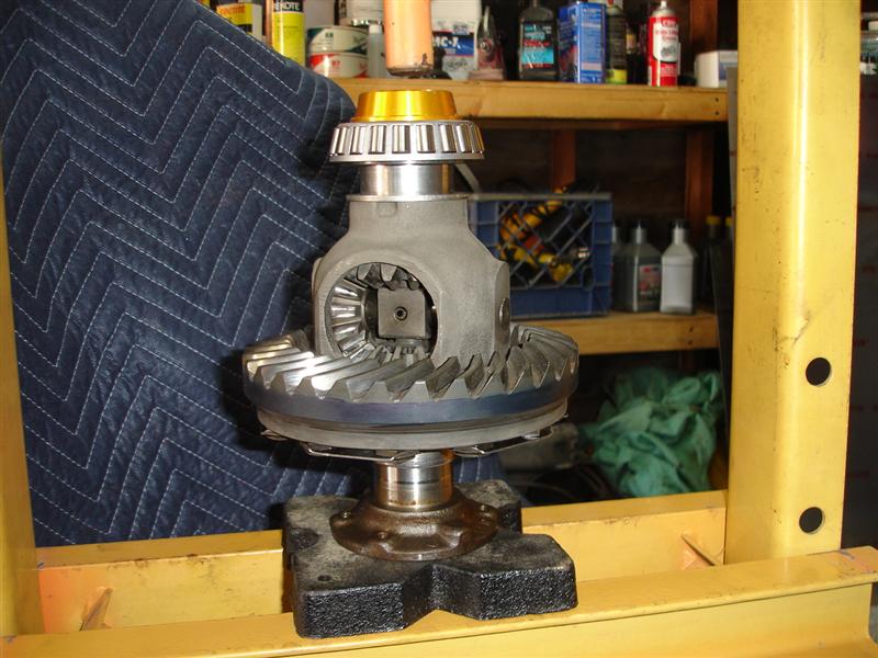
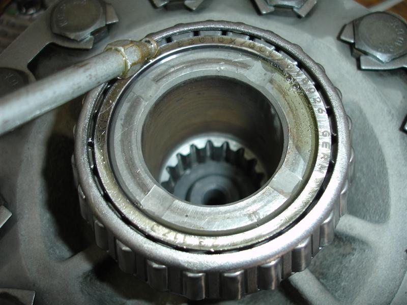
For those that don't recognize it, P258 is commonly created from a used differential housing. I think the early smaller housing tend to be the best for creating this tool. It is used to measure the distance between the axis of rotation of the differential to the tip of the pinion shaft.
One tip for newbies, make sure you have good preload on the diff bearings that you use for this tool. If the clamping force from the differential cover it is not relatively tight, you will have inconsistent and non-reproducible pinion depth measurements. So when you measure the depth using P258, check it a few times after rotating the tool to make sure it is consistent and reproducible. If you can push against the shaft while you measure and it makes a difference, you are seeing the bearing move around and the preload is not tight enough.
QUOTE(mrbubblehead @ Mar 14 2013, 03:44 PM)
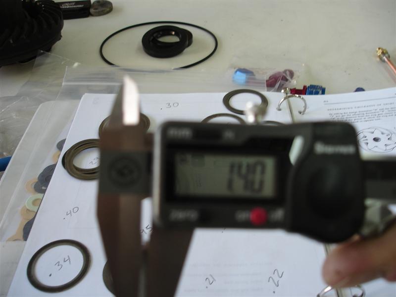
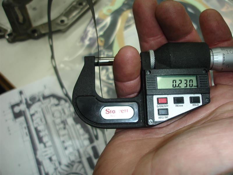
...the gasket "kit" comes with three gaskets, but they are all the same thickness. and close dosnt work. i believe they are 0.20mm but porsche offers them in 0.15 and .10mm. you will have to use an assortment of different thicknesses to hit the mark.
I have found that the gaskets in the Elring Klinger kits to be the same as you say. I have also found that because after doing a number of rebuilds you have extra gaskets (you don't always need the three they provide) and that there is slight variances in them. So I was able to measure, and sort and sometimes create more ideal matches when I needed to use multiple gaskets. It would be nice if there was an easy source for the old style thicknesses. The old ones used to be color coded and/or had watermarks that indicated the thickness. Regardless, always measure your gaskets to verify thickness.
QUOTE(mrbubblehead @ Mar 14 2013, 03:44 PM)
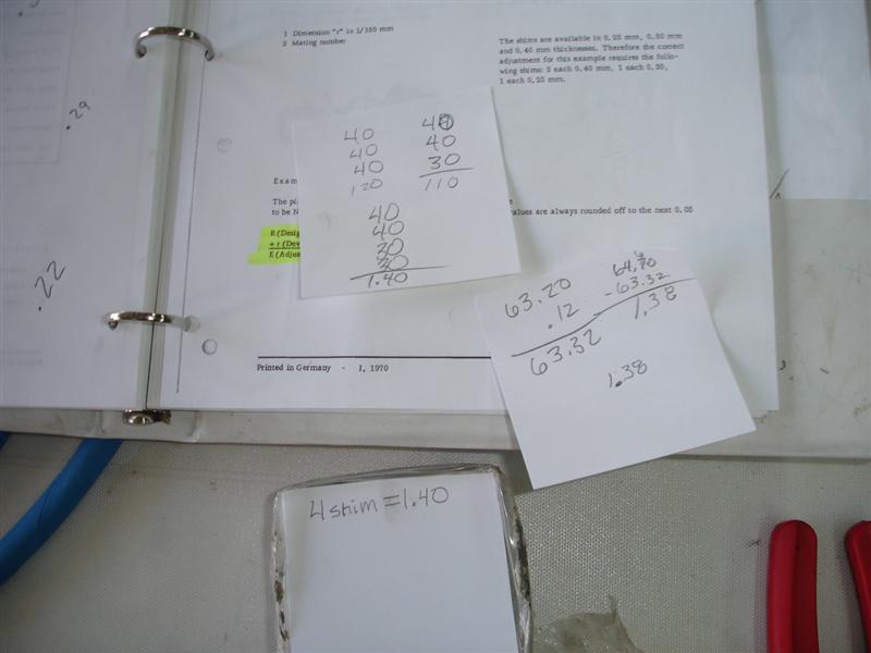
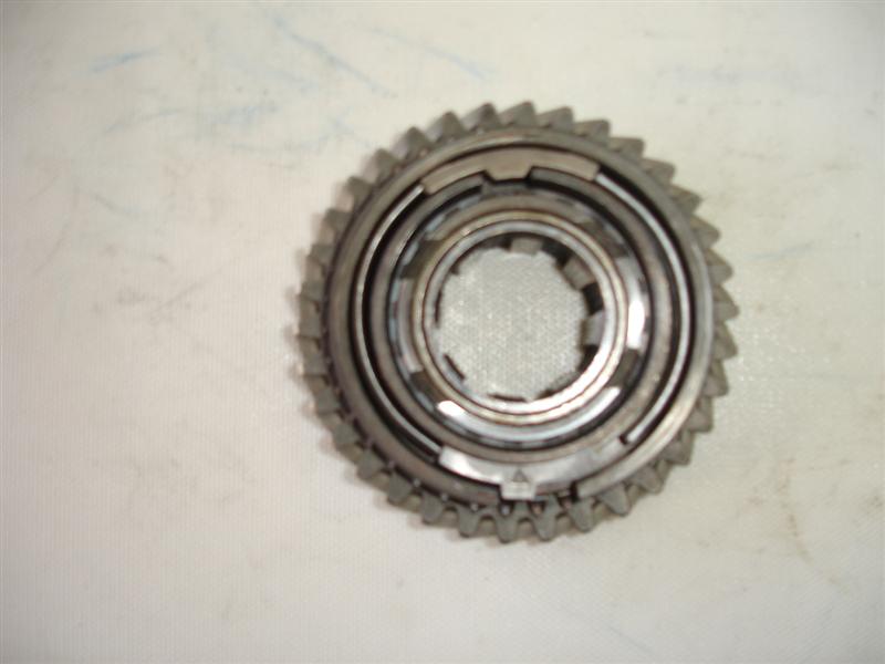
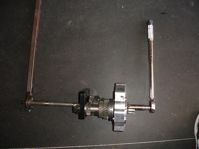
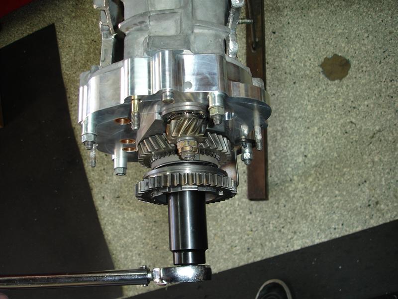
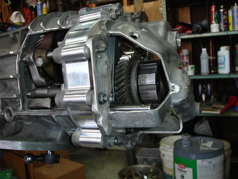
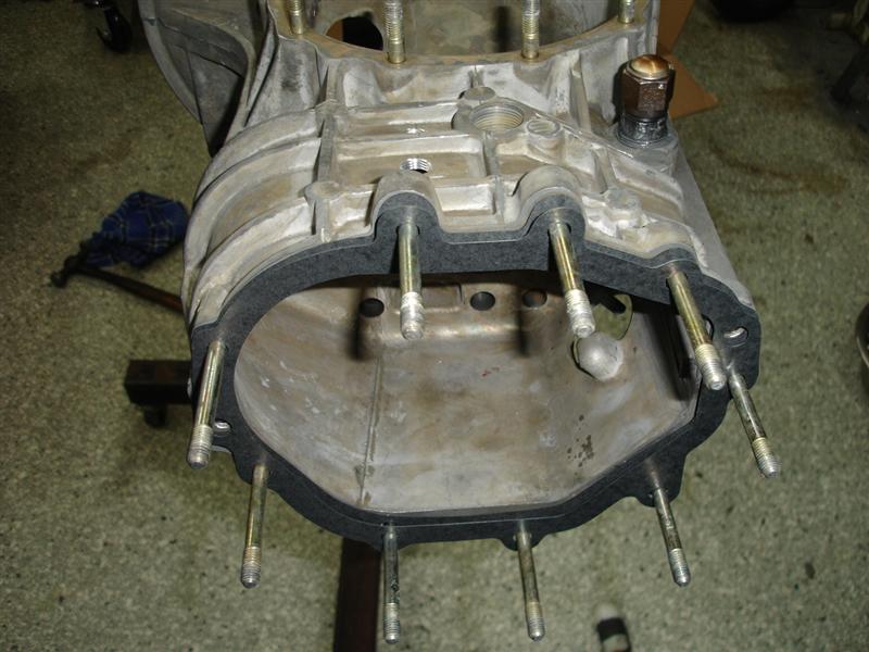
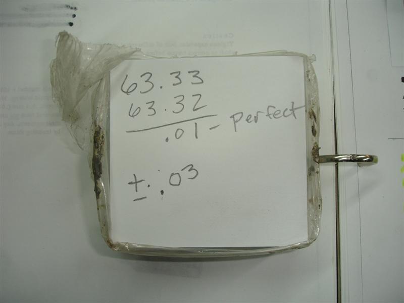
...sorry no pictures of the back lash adjustment, but there is one in the book. essentially what the backlash measurement is to mesh the ring gear to the pinion shaft. not to tight and not to loose (slop). this is a tedious job because you have your total shim thickness from both sides of the diff (preload). now you have to mix those shims to raise or lower the ring gear. it is alot of work pressing bearings off and on, swapping shims, assembling everything, measure, disassemble and do it as many times as necessary.
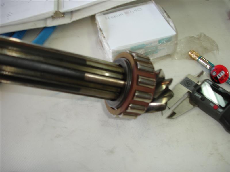
One tip for newbies who do their own backlash measurement. You really have to make sure you are measuring the correct backlash. With the differential cover on, you are measuring a movement you can't directly see. You have to make sure all the correct things are locked down, otherwise, you might end up measuring the slop between the flange splines and the splines inside the differential or the backlash between the pinion and main shaft. You have to lock down the pinion shaft and make sure the flange is tight to the differential carrier. Then the only movement should be between the ring and pinion.
You also mentioned earlier about measuring preload (via rotational resistance) without the flange seals in place. In case it isn't obvious to others as to why it is done that way, you want to measure just the drag of the bearings and not the bearings plus the drag from the seal.
QUOTE(mrbubblehead @ Mar 14 2013, 02:45 PM)
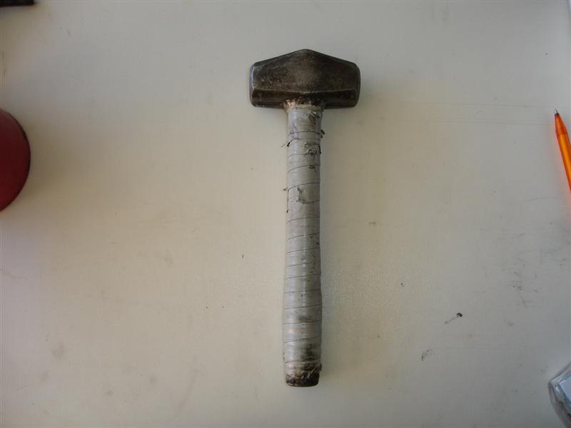
...and my favorite BFH
I know there is a "homemade tools" thread elsewhere. It would be funny to start a "favorite hammer" thread. I have two. One big and one small.
Richard

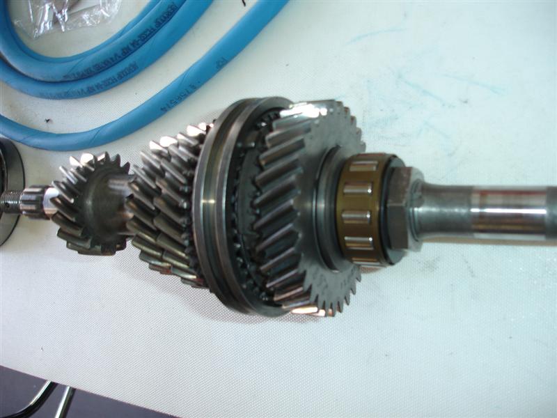
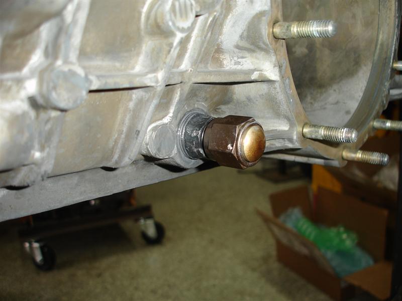
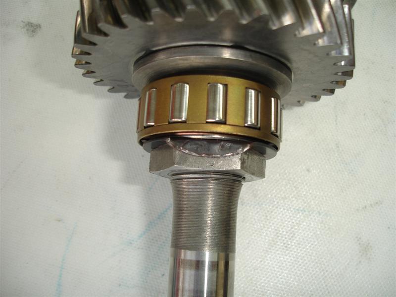
 its for the big nut that holds the whole shmeer together.

![popcorn[1].gif](http://www.914world.com/bbs2/style_emoticons/default/popcorn[1].gif)


 (CALI)
 . what a disaster.