QUOTE(hyespeed @ Jun 1 2016, 07:35 PM) 
There is an older body kit still in the box, I don't plan on using it and I'm not sure he was either. I have spare parts as well including doors, quarter panels, seats, etc.


 And judging from that #4 positive cable I'm guessing it was north of 200w. And judging from that #4 positive cable I'm guessing it was north of 200w.
 The top of that rollbar must be 2" above the drivers helmet, UNLESS that height would interfere with the operation or fit of the OEM top. In that case the driver's helmet must be below a straightedge bridging between the top of the windshield header and the top of the rollbar over the driver's head(the "broomstick test").
 And judging from that #4 positive cable I'm guessing it was north of 200w. And judging from that #4 positive cable I'm guessing it was north of 200w.
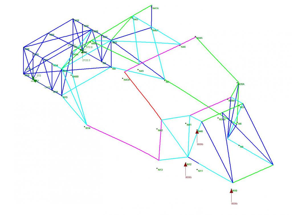
 Love this kind of input. Now to answer some of your questions. The lower A arms were not loaded, what you are seeing is the 3 points where the suspension cradle is bolted to the chassis. The 900 lb vertical load represents a 5g load on the wheel. The next step will be to simultaneously load a 900 lb load in a downward fashion on the opposing suspension cradle support points to create a couple, or rather twisting of the frame as you mentioned. I will be running the same scenario at the rear and then run another scenario to simulate bending forces in the frame. I will go ahead and model the floor and both firewalls with plate elements and see what happens. Might as well model the "longs" as well. this will give a better representation of the behavior.
![popcorn[1].gif](http://www.914world.com/bbs2/style_emoticons/default/popcorn[1].gif) Love this kind of input. Now to answer some of your questions. The lower A arms were not loaded, what you are seeing is the 3 points where the suspension cradle is bolted to the chassis. The 900 lb vertical load represents a 5g load on the wheel. The next step will be to simultaneously load a 900 lb load in a downward fashion on the opposing suspension cradle support points to create a couple, or rather twisting of the frame as you mentioned. I will be running the same scenario at the rear and then run another scenario to simulate bending forces in the frame. I will go ahead and model the floor and both firewalls with plate elements and see what happens. Might as well model the "longs" as well. this will give a better representation of the behavior. I get worried that people will take offense to comments like those sometimes.
Love this kind of input. Now to answer some of your questions. The lower A arms were not loaded, what you are seeing is the 3 points where the suspension cradle is bolted to the chassis. The 900 lb vertical load represents a 5g load on the wheel. The next step will be to simultaneously load a 900 lb load in a downward fashion on the opposing suspension cradle support points to create a couple, or rather twisting of the frame as you mentioned. I will be running the same scenario at the rear and then run another scenario to simulate bending forces in the frame. I will go ahead and model the floor and both firewalls with plate elements and see what happens. Might as well model the "longs" as well. this will give a better representation of the behavior. I get worried that people will take offense to comments like those sometimes. 
 .
The bottom plate will also blend into a rear diffuser. I am planning on exiting my exhaust above the rear bumper line.
.
The bottom plate will also blend into a rear diffuser. I am planning on exiting my exhaust above the rear bumper line. so the extra weight will not be a distraction.
 The material was around $1,200
  I'm usually in the office, so if you're by the area come on by.


 The material was around $1,200 Can't wait to see the cart put together!