First I would like to give thanks to Terry, my uncle, for his time on this and my other RGB backlighting project. He has spent more time working on this than he cares to admit. He's more of a Corvette guy, but his vast knowledge and willingness to help, transcends which benefits our community.
Okay, so I have been told that our tachometer has a problem with bouncing. I personally have never seen this problem and I have to admit that I've never really paid much attention to the tach while driving, so I decided to put the signal generator on the tach and see how it performs. This signal generator bypasses the ignition system and provides a clean signal. This also serves as a control because a bad condenser on the dizzy can cause problems as well.
This video shows the untouched tach in its original state running on a function generator. As you will see, it does bounce and over shoot during the sweeps.
https://www.youtube.com/watch?v=rbC37l1z_oA
This next video shows our tach but with a cheap modern 30 dollar tach stuffed inside. The bounce seems to have disappeared, and there is no more overshoot during the sweeps.
https://www.youtube.com/watch?v=cmk1lSop_iE
The VDO tach was designed for mass production and had a very simple but effective design. This modern tach uses an air core massless motor which is controlled by sine/cosine inputs which tends to be a bit more responsive and accurate. The original vdo design is a motor/spring contraption which will always have some bounce. Over time, capacitors and dampening fluid may leak or fatigue which will aggravate the problem.
In this write up, I will show how to incorporate a off the shelf 30 dollar tachometer commonly found at the auto parts store, and make it work with our VDO gauge can.
Full Version: Upgrading the tachometer
First we need to purchase this cheap 30 dollar tach. I have found them readily available at AutoZone.
This write up will implicitly describe how to use this style tach.
Click to view attachment
After buying this tach, go ahead and disassemble it. On the circuit board you will need to look for a revision letter. We are looking for revision letter D, if it's not a D go ahead and reassemble the tach and trade it in for another. Rev A has some problems, and is actually quite different than the D. The shaft size for the needle is smaller than rev D and the electronic layout seems to be dramatically different as well. The picture below shows the revision letter on the circuit board.
Click to view attachment
Next, we will need to remove the selector switch on the back of the circuit board. This selector switch, switches from 4 to 6 to 8 cylinders. This switch will be in the way and hits the back of the gauge can. You can either de-solder this switch, or you can use diagonal cutters to snip the leads.
After you have removed the selector switch, you will need to solder in a jumper wire as shown in the picture below.
Click to view attachment
After the jumper has been soldered, we need to change out a resistor (R9). R9 is shown in the picture below.
Click to view attachment
So remove the current resistor in this location and replace it with a 499k ohm resistor. The reason why this must be done, you will notice that our VDO tach face has the tic marks at certain RPM's and different degree marks than the 30 dollar tach. The VDO face dial is 4 some inches in diameter, and the sunpro tach has a tiny 1.5 inch dial face. The numbers for each RPM simply don't line up, so changing the resistor will fix the gain on the needle sweep and correct with the corresponding angle.
Click to view attachment
This resistor has been carefully calculated for solving this problem at no extra charge to you! However tips are appreciated!
Edit: R9 resistor values:
499k ohm for a 4 cylinder
340k ohm for a 6 cylinder
243k ohm for a 8 cylinder
Now go ahead and cut the white wire near the circuit board. This wire is used for lighting, which you will not need for this project. You will also need to pull all the other wires so they come thru the top of the circuit board. If you leave the wires where they are at, the circuit board will stick too far out from the back of the gauge can.
It should look something like this when you are done. Go ahead and zip tie the wires to the hole in the circuit board. This will be a good strain relief for the mice that might be pulling on the wires under your dash.
Click to view attachment
The electrical portion of this build is now complete. The backside of the circuit board is very clean with no wires in the way. The circuit board should sit nicely inside the gauge can.
Click to view attachment
So remove the current resistor in this location and replace it with a 499k ohm resistor. The reason why this must be done, you will notice that our VDO tach face has the tic marks at certain RPM's and different degree marks than the 30 dollar tach. The VDO face dial is 4 some inches in diameter, and the sunpro tach has a tiny 1.5 inch dial face. The numbers for each RPM simply don't line up, so changing the resistor will fix the gain on the needle sweep and correct with the corresponding angle.
Click to view attachment
This resistor has been carefully calculated for solving this problem at no extra charge to you!
However tips are appreciated! Edit: R9 resistor values:
499k ohm for a 4 cylinder
340k ohm for a 6 cylinder
243k ohm for a 8 cylinder
Now go ahead and cut the white wire near the circuit board. This wire is used for lighting, which you will not need for this project. You will also need to pull all the other wires so they come thru the top of the circuit board. If you leave the wires where they are at, the circuit board will stick too far out from the back of the gauge can.
It should look something like this when you are done. Go ahead and zip tie the wires to the hole in the circuit board. This will be a good strain relief for the mice that might be pulling on the wires under your dash.
Click to view attachment
The electrical portion of this build is now complete. The backside of the circuit board is very clean with no wires in the way. The circuit board should sit nicely inside the gauge can.
Now the machining part. Go ahead and remove the gauge bezel ring with a small screwdriver. Carefully uncrimp the lip that holds the bezel ring in place. After this ring has been removed, go ahead and remove the glass and the inner bezel ring. Next you'll need to remove the 4 small screws on the back of the can. Next, remove the tach from the can. It should look like this after you are done.
Click to view attachment
Carefully put aside the tach assembly that you just removed from the can. We will come back to this later.
Now obtain a 9/64" drill bit. You will need to enlarge these 2 holes.
Click to view attachment
With the holes slightly bigger, you can now use the same screws that came with the 30 dollar tachometer to secure the circuit board inside the VDO can.
Click to view attachment
Carefully put aside the tach assembly that you just removed from the can. We will come back to this later.
Now obtain a 9/64" drill bit. You will need to enlarge these 2 holes.
Click to view attachment
With the holes slightly bigger, you can now use the same screws that came with the 30 dollar tachometer to secure the circuit board inside the VDO can.
Now the fun stuff. You will need one of these.
Click to view attachment
This is a adapter bracket that will mount to the modern circuit board, but will also allow you to mount the 914 face dial to it.
Below is the specs for this bracket. Take this drawing to any machine shop, they should have no problem making you one.
Click to view attachment
I am very fortunate to have a family member that happens to own a machine shop. This particular bracket was made via a waterjet machine.
After you have obtained said bracket, you will need to remove the plastic bracket on the sunpro's motor. See picture below. Remove this bracket and discard of it.
Click to view attachment
Now grab the old tachometer that you pulled apart earlier. Carefully, (can't stress this enough) pull the needle straight up. Some force might be involved to remove this needle. Next, remove the 2 screws (some have 3) that are on the 914's face dial. With the face dial removed, go ahead and wipe it off and remove any oily finger prints. The sunpro tachometer will need to have its threads re-tapped to accommodate the new screws for the mounting bracket.
Use this tap on the sunpro's motor plastic bracket: 8305A77 Metric high speed steel hand tap 2x.4mm, D3 pitch diameter, 3 flute After these 2 holes are re-tapped go ahead and counter sink the 2 holes with this counter sinking bit: 2846A124 Single-Flute high speed steel countersink 90 degree angle, 3/8" body diameter, 1/4" shank diameter.
Next, mount the adapter plate on the sunpro tach mounting plate. Use these screws: 91698A202 metric 18-8 stainless steel flat head phillips machine screw black-oxide M2 size, 6mm length, .4mm pitch. Make sure the holes on the adapter plate are counter sunk, and the screws are flush with this bracket.
Now mount the 914 face dial to the adapter plate. You can re-use your old screws if they aren't too scratched up. Or you can use these screws: 95836A105 metric pan head phillips machine screw black-oxide 18-8 stainless steel M2 size, 4mm length, .4mm pitch
It should start looking pretty good. You should now have the modern circuit board mounted to the 914 face dial. There is one last thing you'll need to do with machining, the needle. The needle won't simply push back on the shaft. You will need to drill the hole a size bigger. Obtain a 0.037" drill bit, and chuck it up to a dremil. After the needle has been honed out, hold off from re-installing the needle. We will need to calibrate it first.
So now we need to assemble this back into the can. Use this hole to loom the wires thru the back of the can.
Click to view attachment
This mod was intended to re-use holes and doesn't require you to drill new ones which will ruin your gauge can. If you use this hole, you will lose one light port for your tach. This is a great time to upgrade to LED lighting. See my topic "custom gauge backlighting" for further explanation.
This is a picture with the wires running thru the back of the gauge can
Click to view attachment
Put a couple nylon washers between the back of the gauge can and the circuit board. This spaces the circuit board, so nothing shorts out. I ended up using 2 nylon washers per screw.
Click to view attachment
Now we need to apply power to this. The red and black wire goes to the battery. The green wire goes to the black/purple striped wire. This will be a very crude calibration technique, but if you don't have access to a function generator this will do.
Applying power will zero the shaft, this is why powering up is so essential. Now pay close attention to the picture below.
Click to view attachment
Put the needle back onto the shaft at this same spot. This should get you very close to correct.
Reinstall the glass and bezel ring and enjoy!
Very cool! Have you verified this with the points-and-condensor setup that the 914s run? Modern signals may be significantly cleaner than the signal that the old 914 setup generates.
--DD
--DD
QUOTE(Dave_Darling @ Aug 11 2013, 08:04 PM) 
Very cool! Have you verified this with the points-and-condensor setup that the 914s run? Modern signals may be significantly cleaner than the signal that the old 914 setup generates.
--DD
Never mind my noisy valve lash adjustment
 ***my 914 shown in this video has a stock ignition points/coil setup***
https://www.youtube.com/watch?v=fPk_A1PzbuY
Wow. Thank you for the amazing work.
Will the new tach internals still accept the stock tach input?
I have one of those funny MSD tach sensing adaptors to adopt my stock tach to work with my computerized ignition. I'd guess I leave it as it is?
Will the new tach internals still accept the stock tach input?
I have one of those funny MSD tach sensing adaptors to adopt my stock tach to work with my computerized ignition. I'd guess I leave it as it is?
Looks really nice and thanks for the work. Do you know if it will with the CDI ignition on a -6? (yes I know you have to jumper it for a 6)
Here's the manual for this unit tach manual
It works with the stock point/ignition coil signal setup. It will also work with the modern 5volt systems. This is the beauty of using a true universal tach! lol This write up was for the 4 cylinder cars. Calculations are needed for using this on a 6 cylinder. R9 will change value slightly, most likely a 340k resistor.I will need to post another picture showing where the jumper should be on a 6 as well (jumper stays in the same place). On a CDI system, I assume the output is a standard 5volt square wave? If so, this will have no issue working in tandem with that setup.
It works with the stock point/ignition coil signal setup. It will also work with the modern 5volt systems. This is the beauty of using a true universal tach! lol This write up was for the 4 cylinder cars. Calculations are needed for using this on a 6 cylinder. R9 will change value slightly, most likely a 340k resistor.
How much for you to do it Tim? Not sure how bouncy mine will be with the subie but I will know very soon. I'm sure everyone is wondering...
QUOTE(Chris H. @ Aug 12 2013, 06:30 AM)
How much for you to do it Tim? Not sure how bouncy mine will be with the subie but I will know very soon. I'm sure everyone is wondering...
I'm currently offering a service for upgrading our gauges to the RGB led backlighting. I'm thinking about offering this as an add on service for those that will have me perform the labor. As of right now, I was thinking of charging an additional 100 dollars to do this tach conversion
Tim,
You are unstoppable. Nice work man. I like upgrades that are cheap, especially when harnessing newer technology.
You are unstoppable. Nice work man. I like upgrades that are cheap, especially when harnessing newer technology.
The video below shows the tachometer running on 5volts tach signal.
https://www.youtube.com/watch?v=uUzPC8mEMMI
So, testing is complete with this. The tach will work with our stock setup, where the tach signals are greater than 200volts and it will also work with the modern tach 5 volt signals.
https://www.youtube.com/watch?v=uUzPC8mEMMI
So, testing is complete with this. The tach will work with our stock setup, where the tach signals are greater than 200volts and it will also work with the modern tach 5 volt signals.
Now I need a motor that will run through the gears that fast!
Just ordered my Sunpro CP7911 off Amazon. This is awesome! Can't wait.
The stock tach doesn't work will with my MicroSquirt without a tach adapter. This solves that problem for me as well.
The stock tach doesn't work will with my MicroSquirt without a tach adapter. This solves that problem for me as well.
QUOTE(McMark @ Aug 12 2013, 10:59 PM)
Just ordered my Sunpro CP7911 off Amazon. This is awesome! Can't wait.
The stock tach doesn't work will with my MicroSquirt without a tach adapter. This solves that problem for me as well.
Any progress? What version tach did you get from Amazon?
![popcorn[1].gif](http://www.914world.com/bbs2/style_emoticons/default/popcorn[1].gif)
Got it modded and installed. Had to order the 499k resistor from Mouser. Now I just need to swap in the MicroSquirt brain that doesn't have a fried tach output. 
Nice. One minor flaw has been found with this retrofit. The ground wire which attached to the tach was also grounded the the gauge can internally. You will need to find a way to ground the gauge can, or funky things will happen with the indicator lights.
I have recently found a way to re-use the original terminal block with this upgrade, which retains the proper grounding of the gauge can.
I have recently found a way to re-use the original terminal block with this upgrade, which retains the proper grounding of the gauge can.
Yeah, I installed mine with the factory connector panel as well.
I'll be ordering one of these tachs today. Awesome.
Zach
Zach
Not particularly interesting, but here's mine in action. I left the glass off and used the sunpro needle because I'm going to install a better gauge face. So this was just testing.
https://www.youtube.com/watch?v=2dV0nrNG57A
https://www.youtube.com/watch?v=2dV0nrNG57A
Not bad at all Is this running off a 5volt pulse?
Is this running off a 5volt pulse?
Not sure. I'll have to look at how I have the MicroSquirt set up. I just plugged it in and it worked and didn't think about it again.
Hmmm. Now this has me thinking about gutting the rest of them and making custom faces too.
Great thread, and super helpful for those of us with other computers/engines installed.
Great thread, and super helpful for those of us with other computers/engines installed.
For the price, it's a great project to do. I'm making another one of these this weekend, I'll update this thread with resistor values for a V8
I just finished a tach conversion for a V-8. R9 needs to be 243k ohms
Does this mean that the switch on the back is always removed/soldered as in the original instruction (first few posts) regardless of the number of cylinders? The R9 value sets the cylinder count?
QUOTE(McMark @ Nov 13 2013, 07:04 PM)
Does this mean that the switch on the back is always removed/soldered as in the original instruction (first few posts) regardless of the number of cylinders? The R9 value sets the cylinder count?
Yes
Can you edit you original thread at the R9 step and put the values for each setup?
4- 499
6-
8- 243
4- 499
6-
8- 243
Edited the values
Reviving from the dead due to awesomeness! This is great.
Is there a way it could be made for 2cyl motors? I have many motorcycles that would benefit form the ability to customize the gauges.
Is there a way it could be made for 2cyl motors? I have many motorcycles that would benefit form the ability to customize the gauges.
Thanks  Yes, R9 can be configured from a 2 cylinder to a 32 cylinder. With that said, the variable of the equation would be the 914 tach face. In this thread, R9 was computed for the linearity of our 914 tach. New calculations would be needed for a different style tach face with the number of cylinders desired.
Yes, R9 can be configured from a 2 cylinder to a 32 cylinder. With that said, the variable of the equation would be the 914 tach face. In this thread, R9 was computed for the linearity of our 914 tach. New calculations would be needed for a different style tach face with the number of cylinders desired.
Hi Tim, Reading thru this post, did you decide to do this for folks that wish to send you their tach? (sent a pm but did not hear back). If so, I'd be interested in sending you my tach for the bounce mod, and conversion to six cylinder function. Thanks, Tom
This is awesome! Glad to see you are offering this service!
Tim's service is great. I had him do high intensity LEDs in my gauges at the same time. He incorporates a cool circuit that controls the lighting as well! My gauges are set to gradually switch over from white to bright red as I approach the redline (I believe it's Tim's avatar). Makes driving at night a LOT of fun.
QUOTE(rnellums @ Jan 22 2016, 03:14 PM)
Tim's service is great. I had him do high intensity LEDs in my gauges at the same time. He incorporates a cool circuit that controls the lighting as well! My gauges are set to gradually switch over from white to bright red as I approach the redline (I believe it's Tim's avatar). Makes driving at night a LOT of fun.
Hope to hear back from him!
As a HVAC tech, I've been busy with this recent snap of cold weather. Sorry for not replying to your PM. Tom, you mentioned that you are installing a Honda V6 which I'm not familiar with the ECU's tach signal, it may be canbus. It could work but I can't tell you that it will with 100% certainty. You can do a quick test by purchasing the tachometer from AutoZone and temporarily wiring it. Set the slider switch to 6cylinder and try it. If it works, box up your 914 tach along with the Autozone 30 dollar tachometer, and I would be happy to put it together for you. If it doesn't work, simply return the tachometer to the part store
QUOTE(timothy_nd28 @ Jan 23 2016, 09:29 AM)
As a HVAC tech, I've been busy with this recent snap of cold weather. Sorry for not replying to your PM. Tom, you mentioned that you are installing a Honda V6 which I'm not familiar with the ECU's tach signal, it may be canbus. It could work but I can't tell you that it will with 100% certainty. You can do a quick test by purchasing the tachometer from AutoZone and temporarily wiring it. Set the slider switch to 6cylinder and try it. If it works, box up your 914 tach along with the Autozone 30 dollar tachometer, and I would be happy to put it together for you. If it doesn't work, simply return the tachometer to the part store
Thanks Tim, sounds like a good plan, hope it works, and I can send it along to you.
Might as well take the chance to give another bump to a great member and an awesome service. Send Tim your gauges for all your needs. Even if you don't do the LEDs, his refresh of the gauges is second to none. And of course, he's an awesome guy who's helped out a lot of folks here.
I have some bad news as it seems that AutoZone has recently jumped ship with their gauge supplier. They're now stocking a tachometer that looks very much like the Sunpro Super Tach II but internally it's nowhere near the same. AutoZone's replacement tachometer called the EQUUS (picture below) is completely digital as it has a micro-controller. Changing a resistor value will have no desirable effect with this tachometer. The SunPro tach is still available thru eBay and Amazon, but it's just a matter of time before this supply dries up too. So a heads up for those contemplating with the current tach upgrade, I would do it soon.
I will mess around with this EQUUS tach, it's still only 30 dollars. I will make available a new DIY for this tach conversion as soon as everything is figured out. With this said, I'm not a computer programmer. The new tach uses a micro controller called "ATTiny 24a". I would need to find out a way to extract the current code (chip is surface mount), then modify the code to work with our 914 gauge face and with 914s with different engines, and finally write the modified code back to the chip. Any programmers willing to help, please chime in or PM me
Click to view attachment
I got mine thru Summit a few months back and it was being clearanced for $5.00. I looked at Autozone and they didn't have it so I looked online and found it at Summit. I figured that they were being fazed out. I did the conversion and couldn't find a 490k resister and ended up using a 510k. Seems to work fine.
Good news for anyone wanting to do this. I recently picked up a Bosch mini tach and stripped it down. Looks to be the identical guts.
Bosch FST 7904
Click to view attachment
Bosch FST 7904
Click to view attachment
Taking another approach. Thought I would share.
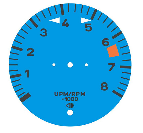
I was liking the idea of a different color gauge face a'la the Singer Porsches. (er, some of them) I thought that instead of messing around with the resistor, why not change the face to display the lines/numbers in the same orientation and spacing as the aftermarket tach, ya know, since I was changing the face anyway.
I measured out the Bosch tachometer in the two previous posts and created a drawing with the lines at the same angles and spacings. The only difference is the face is sized to fit within the VDO tach, and I used VDO style text and lines.
I placed my redline where I wanted, from what I could tell this is the proper redline for the engine I'm putting in, from a 1971 911T. Obviously this can be changed easily to match the engine/car.
Black
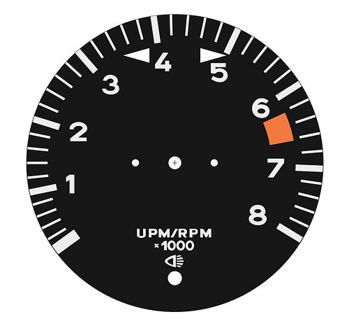
Blue
The workflow here would follow the same steps for removing the selector switch on the rear and routing the wires. It would skip the resistor change. You would still follow the mounting bracket instructions. And you would add the new face.
I have a really high quality printer at home, so I'll try printing my gauge face on high quality luster paper first. If that doesn't turn out I'll probably look into having the image printed on aluminum.
If anyone else is interested, I can send you the SVG file I made. This is a vector file that you can open using Adobe Illustrator ($$$) or Inkscape (free) With this file you can change your redline, gauge color, line/number color, or even add other graphics. Just shoot me a PM with your email address.
I was liking the idea of a different color gauge face a'la the Singer Porsches. (er, some of them) I thought that instead of messing around with the resistor, why not change the face to display the lines/numbers in the same orientation and spacing as the aftermarket tach, ya know, since I was changing the face anyway.
I measured out the Bosch tachometer in the two previous posts and created a drawing with the lines at the same angles and spacings. The only difference is the face is sized to fit within the VDO tach, and I used VDO style text and lines.
I placed my redline where I wanted, from what I could tell this is the proper redline for the engine I'm putting in, from a 1971 911T. Obviously this can be changed easily to match the engine/car.
Black
Blue
The workflow here would follow the same steps for removing the selector switch on the rear and routing the wires. It would skip the resistor change. You would still follow the mounting bracket instructions. And you would add the new face.
I have a really high quality printer at home, so I'll try printing my gauge face on high quality luster paper first. If that doesn't turn out I'll probably look into having the image printed on aluminum.
If anyone else is interested, I can send you the SVG file I made. This is a vector file that you can open using Adobe Illustrator ($$$) or Inkscape (free) With this file you can change your redline, gauge color, line/number color, or even add other graphics. Just shoot me a PM with your email address.
I'm giving it a shot. Still have a lot to learn with even the very basic stuff but got a good start thanks to glen.
Wow, i thought the sunpro's were long gone. Thanks for doing the leg work with the Bosch tach. Keep posting pics, I love to see your twist on this conversion.
This is a good approach. This would also work with the Equus Tach wouldn't it?
Taking another approach. Thought I would share.
I was liking the idea of a different color gauge face a'la the Singer Porsches. (er, some of them) I thought that instead of messing around with the resistor, why not change the face to display the lines/numbers in the same orientation and spacing as the aftermarket tach, ya know, since I was changing the face anyway.
I measured out the Bosch tachometer in the two previous posts and created a drawing with the lines at the same angles and spacings. The only difference is the face is sized to fit within the VDO tach, and I used VDO style text and lines.
I placed my redline where I wanted, from what I could tell this is the proper redline for the engine I'm putting in, from a 1971 911T. Obviously this can be changed easily to match the engine/car.
Black
Blue
The workflow here would follow the same steps for removing the selector switch on the rear and routing the wires. It would skip the resistor change. You would still follow the mounting bracket instructions. And you would add the new face.
I have a really high quality printer at home, so I'll try printing my gauge face on high quality luster paper first. If that doesn't turn out I'll probably look into having the image printed on aluminum.
If anyone else is interested, I can send you the SVG file I made. This is a vector file that you can open using Adobe Illustrator ($$$) or Inkscape (free) With this file you can change your redline, gauge color, line/number color, or even add other graphics. Just shoot me a PM with your email address.
QUOTE(Optimusglen @ Mar 15 2018, 02:01 PM)
Taking another approach. Thought I would share.
I was liking the idea of a different color gauge face a'la the Singer Porsches. (er, some of them) I thought that instead of messing around with the resistor, why not change the face to display the lines/numbers in the same orientation and spacing as the aftermarket tach, ya know, since I was changing the face anyway.
I measured out the Bosch tachometer in the two previous posts and created a drawing with the lines at the same angles and spacings. The only difference is the face is sized to fit within the VDO tach, and I used VDO style text and lines.
I placed my redline where I wanted, from what I could tell this is the proper redline for the engine I'm putting in, from a 1971 911T. Obviously this can be changed easily to match the engine/car.
Black
Blue
The workflow here would follow the same steps for removing the selector switch on the rear and routing the wires. It would skip the resistor change. You would still follow the mounting bracket instructions. And you would add the new face.
I have a really high quality printer at home, so I'll try printing my gauge face on high quality luster paper first. If that doesn't turn out I'll probably look into having the image printed on aluminum.
If anyone else is interested, I can send you the SVG file I made. This is a vector file that you can open using Adobe Illustrator ($$$) or Inkscape (free) With this file you can change your redline, gauge color, line/number color, or even add other graphics. Just shoot me a PM with your email address.
I purchased the Bosch 7904 and it does look like the the right one. I did the full mod and it went real well....until I went to install the pointer. The 914 tach shaft is .5mm and this one is 1mm! A solution will be to drill out the 914 pointer but this will be tricky ans I may end up gluing it onto the shaft.
Were all the 914 tachometers the same. Has anyone run into this? I have a couple more tachometers I could tear into but I don't want to if they are all the same
An thanks Tim for showing us this. I also did the LED lights
Were all the 914 tachometers the same. Has anyone run into this? I have a couple more tachometers I could tear into but I don't want to if they are all the same
An thanks Tim for showing us this. I also did the LED lights
This is a "lo-fi" version of our main content. To view the full version with more information, formatting and images, please click here.