I spent a few hours this weekend with spirit levels and and strings with weights on them trying to figure out if my front end is out of alignment but I'm a bit unsure of the best way to figure this out in a DIY-way.
I crossmeasured the distance between the A-arm mounting holes and the steering rack bolts and they are spot on. How to get a correct mesurement of shock tower I'm more uncertain of but maybe someone here knows?
The root of my concerns: http://matsgarage.com/?p=184
Full Version: Front suspension top measuring.....
To set and measure the front end level, you measure from the A Frame rear bushing mounting bolt to ground and adjust with the torsion bar screws. . . From my experience, when you find the top strut mount holes enlarged, it's often due to worn A-arm bushings not allowing proper alignment.
If the car was hit as your link suggests, you may never get it correct unless the body is straightened. The shock tower was cut to fix the alignment due to the bent chassis.
Yes the crash did probably put the chassis out of alignment but I wonder if there's a DIY-way to check this while I have the car on the rotisserie. I dont want to bolt all the suspension parts back on the body and haul it off to the body shop in the middle of winter with salty roads only to find that its within specificatons.
Level the car.
I found the center of the shock towers by bending a wire in a V shape with the tops of the V bent back down a little to hook on each side of the shock tower. Hang a plumb bob from the V down and measure to the steering rack bolt holes. Do this on both sides. See what the difference is. Only make one bent wire and mark one side. The marked side should always be inboard or outboard. That way if your not completely centered it will be the same on both sides.
Ps, Something that I didn't do that I wish I has is check it FWD and AFT.
Maybe you could drop the plumb bob down from the rear floor pan / fire wall area on each side. Chalk a line and measure back to your shock tower plumb line. You would have to keep your measurement parallel to the center line of the car.
Thanks, I'll have to try that when I get home on friday.
Here's what I did and the results:
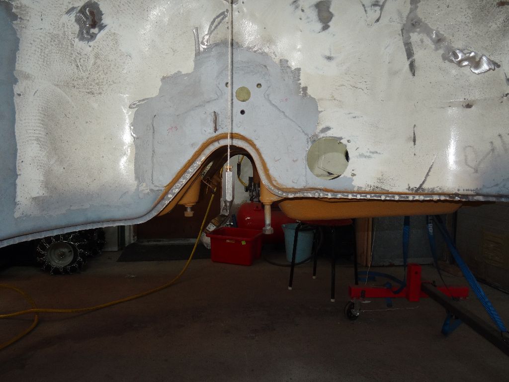
Bent wire holding the plumb.
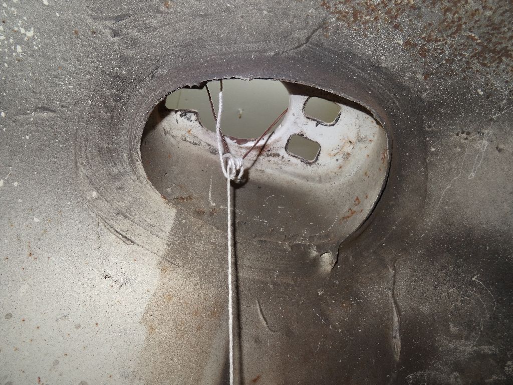
Underside
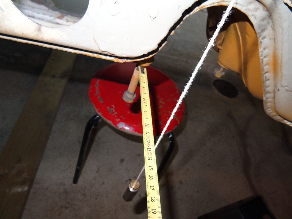
Measuring to the front bolt. Left side was 127 mm. Right side was 128 mm.
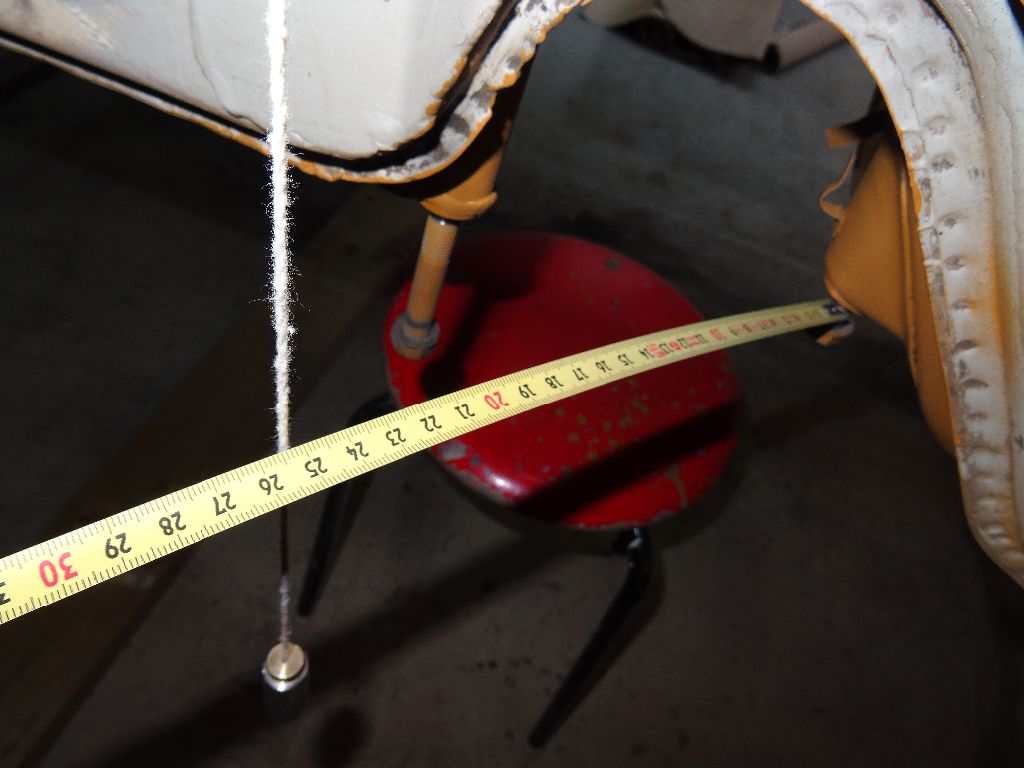
Measuring to the rear bolt. Left side was 249 mm. Right side was 253 mm. I admit the centering of the plumb leaves some margin for error but this was the only measurement that different more than a mm or two.
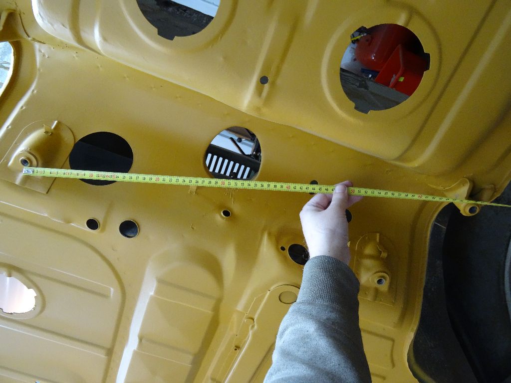
Cross measuring front to rear bolt holes. 677 mm and 678 mm.
I'm a bit surprised the dimensions arent further apart...what does the collective wisdom of 914world think?
Bent wire holding the plumb.
Underside
Measuring to the front bolt. Left side was 127 mm. Right side was 128 mm.
Measuring to the rear bolt. Left side was 249 mm. Right side was 253 mm. I admit the centering of the plumb leaves some margin for error but this was the only measurement that different more than a mm or two.
Cross measuring front to rear bolt holes. 677 mm and 678 mm.
I'm a bit surprised the dimensions arent further apart...what does the collective wisdom of 914world think?
This small part of the collective thinks you need to set the whole shebang up again and re-measure. See if you get the same measurements for several setups. If not, you'll at least have some idea of what the measurement error is.
--DD
--DD
I was thinking that too but I ran out of time having to get the kids from school and daycare and then picking up a birthday gift for the Mrs. I wonder if I can sneak down to the garage tomorrow on her birthday...
I wish I'd spent more time measuring on my last one BEFORE I started doing major body work. This is exactly what I plan on doing all weekend after I get the car stripped.
Great ideas and info!
Great ideas and info!
You had the car good and level?
With that much correction on the PO’s part, I would think you would see big signs of twisted metal?
Could the PO been making up for a bent spindle? Set up for Nascar?

With that much correction on the PO’s part, I would think you would see big signs of twisted metal?
Could the PO been making up for a bent spindle? Set up for Nascar?
1 mm is ok. You should stay within 3 mm and you should be ok. There are no measurements listed for the front suspension mounts as these are located with Celette fixtures. 1 mm there should be ok as long as the chassis is not twisted.
You could check the strut tops by finding center on the cowl and measuring to the furthest bolt hole on both strut tops. Again as long as the chassis is not twisted you can be within 3 mm.
Get the chassis level. Check the center of the car first. Then the cabin with the measurements here.
http://www.914world.com/specs/bodydims.php
Then move out to the front clip.
doublepost....
Did some more measuring today, got another plumb so I could measure both sides at once.
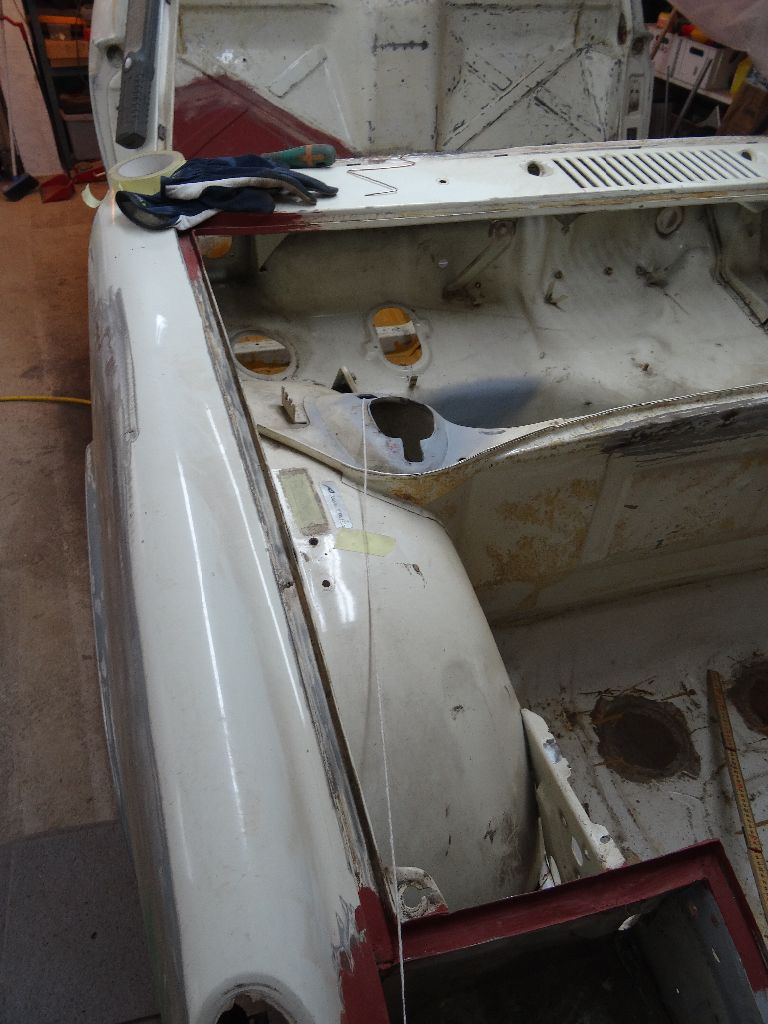
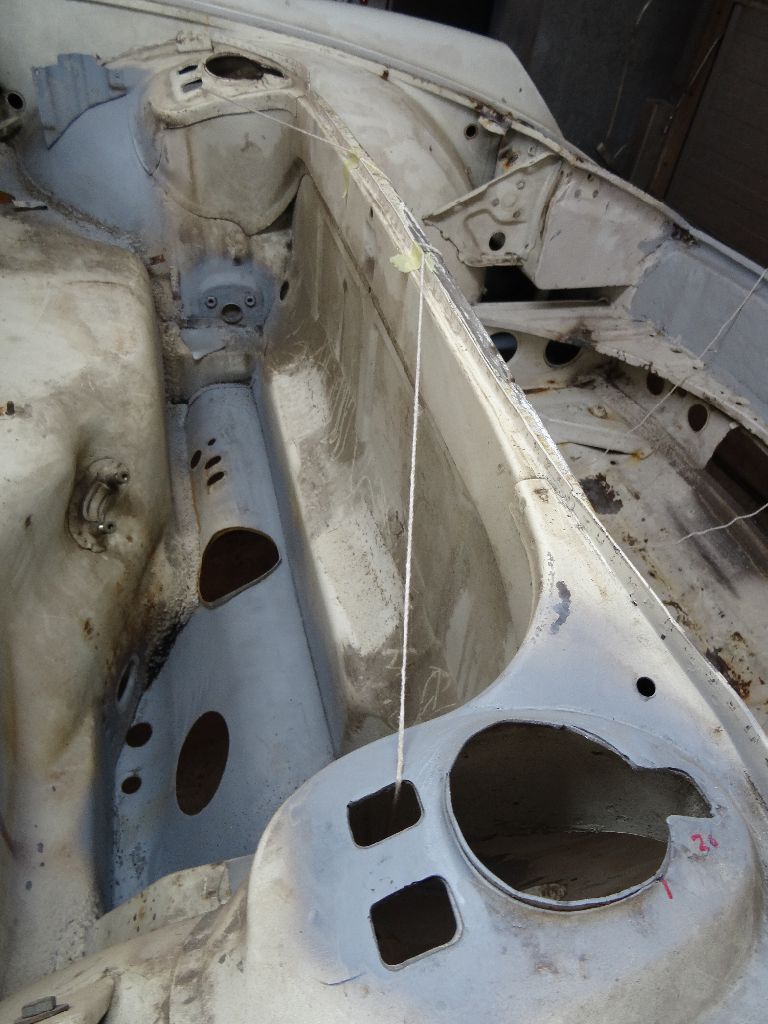
Front right side, plumb hanging from outer hole corner.
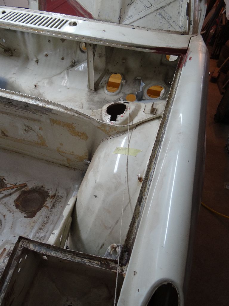
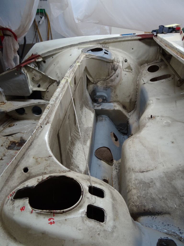
Front left side, plumb haning from outer hole corner.
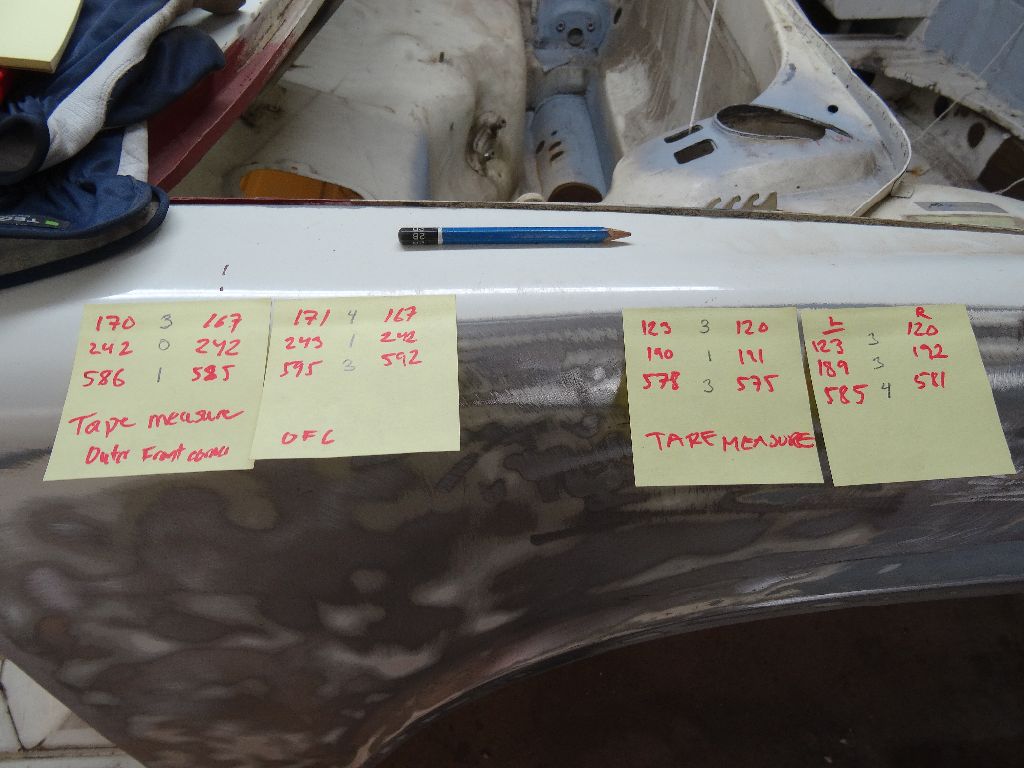
The two left notes are for when the plumb hangs from the outer hole corner. The two right ones for the inner hole corner.
First I measured with a tape measure (left note) and then with a ruler. (right note)
First measurement is to the front steering rack bolt, second to the rear steering rack bolt, third is to the front outer A-arm mounting hole.
I also got a hand from my father-in-law and we measured the cross distance between the front A-arm mounting holes and the transmission rear mounting holes
and both were equal.
Front right side, plumb hanging from outer hole corner.
Front left side, plumb haning from outer hole corner.
The two left notes are for when the plumb hangs from the outer hole corner. The two right ones for the inner hole corner.
First I measured with a tape measure (left note) and then with a ruler. (right note)
First measurement is to the front steering rack bolt, second to the rear steering rack bolt, third is to the front outer A-arm mounting hole.
I also got a hand from my father-in-law and we measured the cross distance between the front A-arm mounting holes and the transmission rear mounting holes
and both were equal.
QUOTE(rick 918-S @ Jan 24 2014, 09:44 PM) 
1 mm is ok. You should stay within 3 mm and you should be ok. There are no measurements listed for the front suspension mounts as these are located with Celette fixtures. 1 mm there should be ok as long as the chassis is not twisted.
You could check the strut tops by finding center on the cowl and measuring to the furthest bolt hole on both strut tops. Again as long as the chassis is not twisted you can be within 3 mm.
Get the chassis level. Check the center of the car first. Then the cabin with the measurements here.
http://www.914world.com/specs/bodydims.php
Then move out to the front clip.
Rick,
Do you have a Celette? Mc Mark...
Maybe next time someone has the fixtures on a Celette bench they can take some measurements from the suspension hard points. Something we can reference and tie in with the body dimensions would be nice.
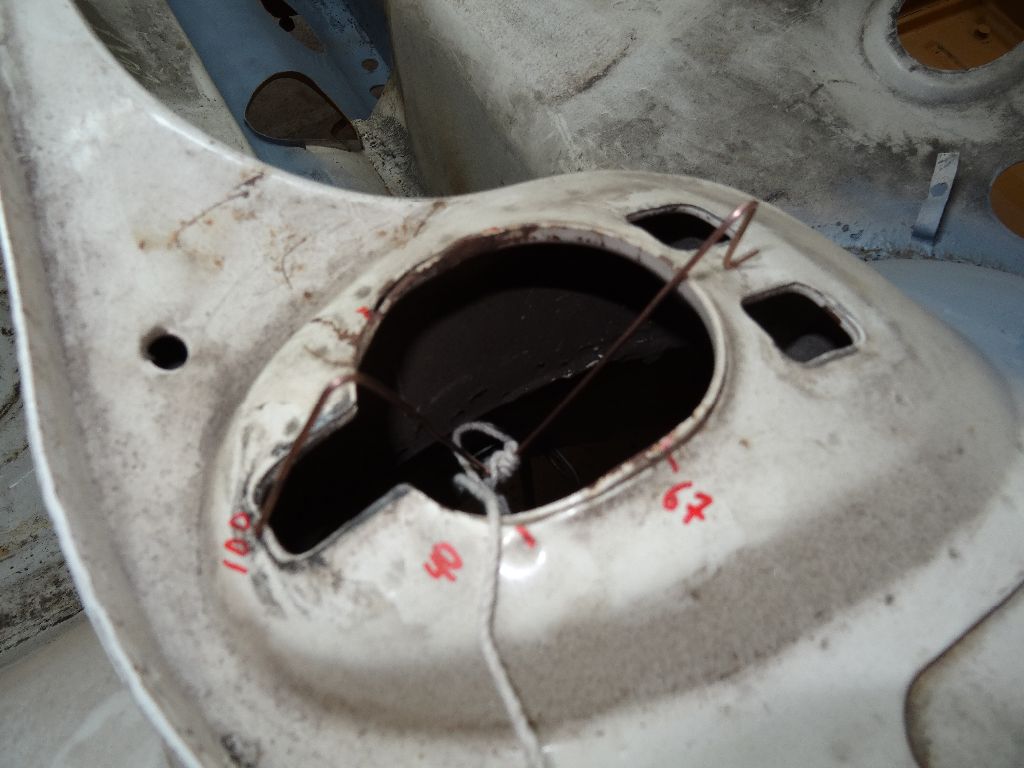
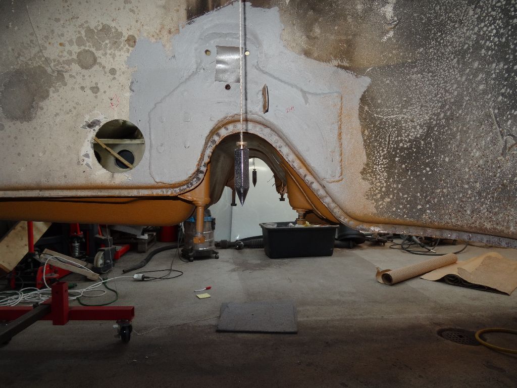
Did some more measuring this weekend and the results was well...expected but a bit sad. I figured that I'd remount the top mounts to the towers, then put a piece of pipe in the hole where the top of the shockabsorber sits and then measure to the steering rack bolts from the lower end of the pipe.
When preparing this I found that the right side (the crashed side) top mount had been cut on the inner side. probably to achieve the right camber setting in combination to filing the top mount holes.
When measuring to the steering rack bolts with the pipe in place there's a difference of several cm's between the right and left side so the body definatly needs to see a professional shop for straightening.
This is a "lo-fi" version of our main content. To view the full version with more information, formatting and images, please click here.