drbill
May 6 2014, 03:56 PM
I know this has been covered and I've read the Pelican article and the "Crusty" method and understand how to do it.
This question is just as a point of clarification. In the PP article, they mention a notch on the flywheel which can be seen/felt at the opening on the top of the transmission when #1 cylinder is at TDC. I have #1 at TDC, based on the rotor pointing at the notch on the dizzy and the notch/groove on the impeller fan lining up with the housing there.
However, there is no notch on top (or bottom) of the flywheel. I can actually see the top of the gearbox and the opening there from inside the engine bay… just nothing there on the flywheel. Someone help alleviate my OCD, please!

r_towle
May 6 2014, 04:27 PM
not all flywheels have a notch...
Carry on.
drbill
May 6 2014, 05:23 PM
QUOTE(r_towle @ May 6 2014, 02:27 PM)

not all flywheels have a notch...
Carry on.
Cool. Thanks!
Triaddave
May 7 2014, 10:08 PM
crawl under and look up, take a flash light, there is a hole...maybe off 180?
drbill
May 8 2014, 06:18 AM
QUOTE(Triaddave @ May 7 2014, 08:08 PM)
crawl under and look up, take a flash light, there is a hole...maybe off 180?
The car is actually on a lift in my garage. I looked underneath at the hole and can see the flywheel, but no notch and no notch at the top, either. I will rotate it around completely to see if it's even there.
stugray
May 8 2014, 07:20 AM
I bet it is there.
realize that you need to turn the FW 10 deg to get the dist to move 5 deg.
The window is only a couple degrees wide so the mark zooms by the window with a barely perceptible move in the dist rotor (put the car in 5th gear)
And by now I think you realized that you can see through the upper transmission hole from the engine compartment.
You just have to pop the rear engine tin back a bit.
I stick a sharpie in the gap to view the hole when I set my timing.
TDC on #1 = notch on top. TDC#2 = notch on bottom.
So once I found the notch on top, I put a paint mark on the bottom.
Now you can find TDC for each valve in order from the bottom only (no mirrors)
Cap'n Krusty
May 8 2014, 08:23 AM
My endlessly repeated mantra is "why would you want to go to all that to use a method which is inherently slower and not as accurate?" Oh, I forget, you're all 914 owners ...........................
The Cap'n
stugray
May 8 2014, 09:00 AM
QUOTE
My endlessly repeated mantra is "why would you want to go to all that to use a method which is inherently slower and not as accurate?"
Maybe - Because sometimes (either during engine assembly or troubleshooting) it is necessary to:
1 - Truly FIND #1 TDC
2 - cycle through each cylinder TDC in succession?
And as I stated on the other thread, I believe anyone learning to set their own valves, needs to understand the "regular" way before learning your "simpler" way.
Or they will not understand it thoroughly.
If you dont learn the hard way first, you dont properly appreciate the short cuts.
Did you teach your kids how to use a screwdriver first, or did you just give them a screwgun?
(Funny, my son used to make a Wrrrrrrrr sound any time he held a screwdriver up to a screw. Guess he just learned - that's how it works when Dad does it)
drbill
May 8 2014, 07:46 PM
Ok, guys, I found the notch on the flywheel. It came into view when I had my buddy rotate the left rear wheel counter clock-wise, but when it's centered in the opening at the top, the notch/groove alignment on the impeller fan is off and the rotor moves off the notch on the dizzy. Not 180 deg, but just a little. So, which do I go by to determine TDC for #1? I know, I'm being anal, but I'm a perfectionist!

Cap'n: I will use your method, I promise!!
stugray
May 8 2014, 08:40 PM
The notch on the FW is supposed to be the "truth" and everything else is set to TDC from there.
The mark on the fan might be a zero, 5 deg BTDC, or even a 27 BTDC
If you want to be doubly sure you can use a depth gauge in the #1 sparkplug hole, but be careful to not break off a chopstick in there :-)
drbill
May 8 2014, 09:31 PM
Thanks, Stu!

ThePaintedMan
May 9 2014, 07:13 AM
If you're just trying to do a valve adjustment, you don't need to find perfect TDC. You only need to ensure that the intake and exhaust rockers on #1 are indeed "rocking," on the flat part of the cam lobe - this means the valves are closed. Once they're closed, they're as closed as they'll be until you turn the motor again to the point where the lobe starts engaging the lifter again.
stugray
May 9 2014, 07:24 AM
QUOTE
indeed "rocking," on the flat part of the cam lobe
There! You have just highlighted the only flaw in the Cap'ns description of his method.
MOST of the people who read it think the same thing (I did when I first read it).
In his description, "rocking" means the exact opposite of what you mean up there.
I thought "rocking" meant they were loose and on the lower part of the lobe.
To the Capn "rocking" means "the valve is actuating (mostly open)" or "doing what rockers do...."
Cap'n Krusty
May 9 2014, 08:29 AM
"Flaw"? Remember, a "flaw" is, in many cases, an unappreciated "feature". This is one of those cases. For example, I have 6 cars. My wife thinks that's a flaw. We all know this is a feature. I think reducing the pack from 16 to 6 is a flaw. My wife thinks this is a feature. It's all in how you look at it.
The Cap'n
ThePaintedMan
May 9 2014, 01:02 PM
I see what you're saying, but in reality, it's semantics. Cap'ns method is the one I learned and the one one I've ever used, but it made sense to me. Perhaps wobbling is better term? The rocker should be loose if you're trying to adjust it. That's the whole point of adjusting valve lash anyway.
Java2570
May 9 2014, 01:34 PM
I certainly understand the method that the Cap'n is using for valve adjustment but I choose to use
the way that Stu had mentioned just because it's easier for me to remember over time. As I get faster
and more confident (I've only adjusted them 3 x since I got the car) I'll likely adopt the Cap'n procedure.
The thing that struck me when I did mine last week was how easy it is to misread the feeler gauge.
I triple checked all of them because I just didn't feel confident the first 2 times! Until I get the feel down,
I'll just take me time and make an afternoon of it. I don't want to rush and make a mistake....
stugray
May 9 2014, 02:28 PM
If you can find the "Go No-Go" type of feeler gauges, they have a step machined in them.
If I was home I'd take a pic
IIRC - they would machine down the end of the .007 to .005
That way if you want .006, the .005 end will "go" but the .007 would be "no-go" .
I am guessing that the Capn probably has some?
ThePaintedMan
May 9 2014, 02:33 PM
I always do that with a regular set of gauges to check my work. 0.06 feeler, then follow up with a .07 (or maybe it's a .08) to see if it still fits. If it does, I need to tighten the screw a tad more. Only takes a hair longer and it's piece of mind.
Java2570
May 9 2014, 03:05 PM
I am wanting to buy a new set of feeler gauges, so I'll at least check out the go-no-go ones.....
Buying more tools is fun anyway! Next, I want a slide hammer.....
stugray
May 9 2014, 06:27 PM
These are what I'm talking about:
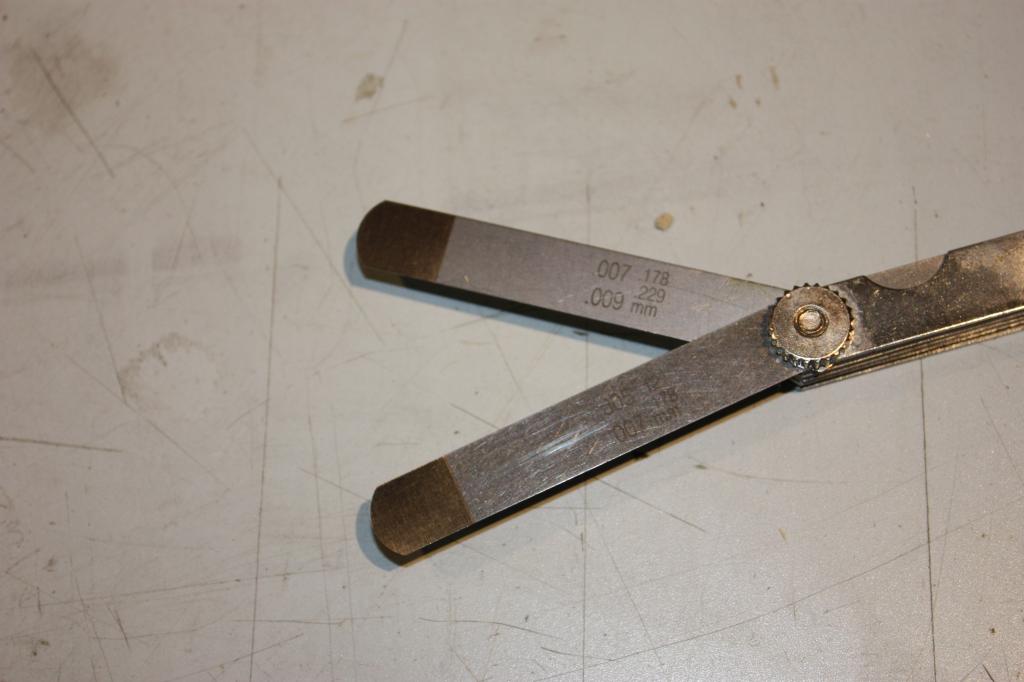
I think I found them at autozone
drbill
May 10 2014, 08:28 PM
Well, job done this afternoon. Not too bad at all. I didn't find it a big deal to do it by getting each cylinder to TDC. Next time I'll try the Cap'n's method.
The rear engine tin was not installed properly at some point, so I spent longer getting that lined up and the screws back in than I did adjusting the valves!

euro911
May 11 2014, 01:08 AM
I drilled a hole in the rear engine tin allowing me to see the TDC slot top-side. I painted the slot with white paint while the flywheel was off. Also painted a mark on 180° out so I could see TDC from below

This is a "lo-fi" version of our main content. To view the full version with more information, formatting and images, please
click here.