Help - Search - Members - Calendar
Full Version: Tach calibration
914World.com > The 914 Forums > 914World Garage
larss
The tach on my -72 914/4 has been very inaccurate (showing 3000rpm at real 3500rpm) and also wery bouncy. After reading some good threads in this and other sites I decided to follow some of the tips on how to calibrate the gauge and reduce the bouncing.

NOTE, the below links shows gauges of many generations, some tips may not be valid for some tachos! Also with these tips I just want to show how I did it with no guarantees that it will work for others.

This article describes how to open the tach:
Open the Tach

This thread describes how to reduce the bouncing by adding a 2200uF electrolytic capacitor.
Reduce bouncing

This tread hints about the wire wound resistor R2 being the calibration resistor.
Caibration resistor


My tach is of the early 914 type, (I think the circiut was slightly changed in 73-74), the procedure may not be identical to later ones.


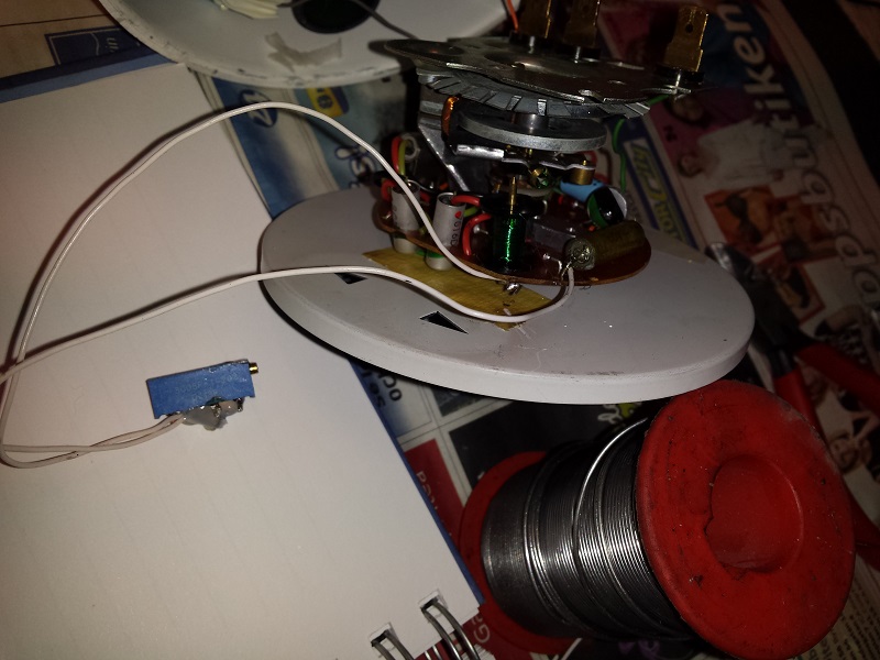
After opening the gauge I glued the condenser next to the right turn signal lens, also I glued the new calibration potentiometer.I drilled a small hole so that the potentiometer schrew can be reached without opening the tach again:
IPB Image

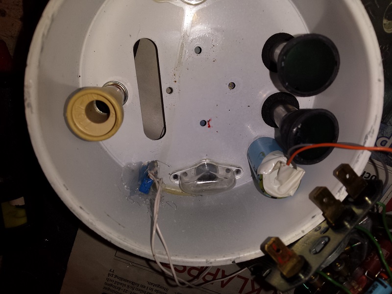
I found the connection points for the condensator to be on each side of the diode (partly hidden in the Picture), important to not mix plus and minus at the new condensator:
IPB Image

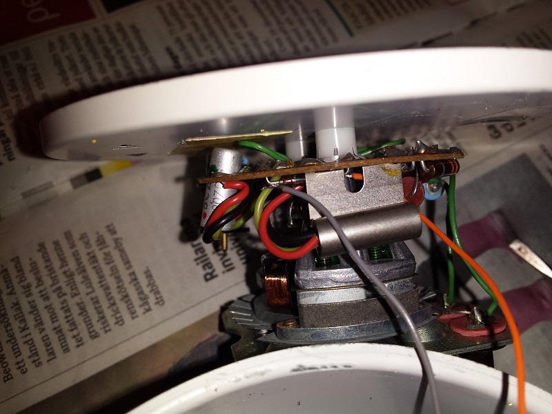
Before I started soldering the potentiometer I found out by testing that I had to reduce the resistance from the existing calibration wire wound resistor "R2".
I used a potentiometer 0 to 2000 Ohms and connected it in parallel to R2 (did not want to cut the old one if I did not have to).
The adjusted value on my potentiometer was around 1000 Ohms (checked with engine running and also a reference tach connected at the same time).
IPB Image

Through the little hole at the back I can make adjustments:
IPB Image

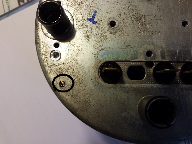
I can now calibrate the gauge from outside (I guess the drift comes from components on the circuit bord getting old so I easily can re-calibrate at more aging).

The bouncing was reduced a lot but not fully elliminated, it is now on the level that I can live with it.


/Lars S


Dr Evil
Cool.
Dr Evil
If anyone in the states wants this mod, I would love to do it smile.gif Condensator = capacitor in US.

This has inspired me to maybe map out the circuits of the various tachs. We have enough EE on here that could then see if there is even more tweaking that could be done. Probably be able to fabricate and build our own boards that do what ever we want (4, 6, 8, 12)
larss
QUOTE(Dr Evil @ May 14 2014, 12:46 AM) *

If anyone in the states wants this mod, I would love to do it smile.gif Condensator = capacitor in US.
....


Sorry for mis-spelling unsure.gif
I followed capacitor mod from Spoke, it is designed for the later type 914 tach, as I wrote it did not fully solve the bouncing problem on my early gauge, I belive more experimenting would be neccesary to test out a good solution also for the early ones.

The main reason for my operation was the gauge showing wrong rpm, (Im no racer and can live with some bouncing), the calibration mod however was more successful, my tach now follows a reference tach to 98%.

I guess the calibration also could have been done by changing some of the aging components (capacitors etc) but this would also have required the calibration resistor to be altered.

QUOTE(Dr Evil @ May 14 2014, 12:46 AM) *

...
This has inspired me to maybe map out the circuits of the various tachs. We have enough EE on here that could then see if there is even more tweaking that could be done. Probably be able to fabricate and build our own boards that do what ever we want (4, 6, 8, 12)


I found the first circuit diagram on this page to be maybe not identical but WERY close to my early gauge type.

Early Tach diagram

More tach diagrams in this thread also:
Tach diagrams


/Lars S
Dr Evil
Lars, you rock! Thanks for compiling all of this in one place. first.gif
This is a "lo-fi" version of our main content. To view the full version with more information, formatting and images, please click here.
Invision Power Board © 2001-2024 Invision Power Services, Inc.