I have a Pertronix Ignitor II that just stopped working.
I did a bench test and it seems like it works...
With the voltmeter hooked up it reads 4.83 volts until I spin the magnet it then goes up to 12.98 volts all four times it spins around.
Click to view attachment
Full Version: Pertronix Ignitor II Test
I think the trigger should read 0 V to collapse the field on the coil.
that seems to have a blown diode
that seems to have a blown diode
When I rebuilt the engine I took the distributor out of the old engine and put it on the shelf. Time for new engine, I simply took it off the shelf and installed it back in.
I know I hooked it up properly. I have fried one before.
Its just weird that it stopped working while it was sitting on the shelf.
When I put an old points style distributor the engine fires up and runs fine.
I know I hooked it up properly. I have fried one before.
Its just weird that it stopped working while it was sitting on the shelf.
When I put an old points style distributor the engine fires up and runs fine.
they supposedly have a problem when the key is left in the on position when the engine is off and burn out from that .
There should be evidence of a hot spot on the sticker on the pertronix unit. Customer service is very good.
David
David
QUOTE(Harpo @ Jan 3 2015, 08:23 PM) 
There should be evidence of a hot spot on the sticker on the pertronix unit. Customer service is very good.
David
No signs of a burned spot or smell.
http://www.pertronix.com/support/tips/
It works. It doesn't work No inbetween. Mine is about 3 years old. My original research said when they decide to quit there's no warning.
It works. It doesn't work No inbetween. Mine is about 3 years old. My original research said when they decide to quit there's no warning.
I dont believe that I can answer your question without a diagram of how you have everything hooked up in your picture above.
My first thought was that everything might be right, but the DMM should not read -12V if that is the case.
You also dont have the coil resistance in the picture, so there is nothing to "drop" the 12V across, so testing without that resistance could stress the pertronix unit.
For the $1M question of the day: WHY do I get WIFI reception inside my microwave?
I wouldn't use the coil for a load as Stugray says; the FET switch inside may get damaged because of high current; this is what can happen when the ignition switch is on and the engine is not running.
You must have some load between +12V and the black wire. For your testing, you can use a standard resistor, like 50 or 100 ohms for a load instead of the coil.
With the resistor as a load, you should alternately measure 0 and 12V as you turn the dizzy.
You must have some load between +12V and the black wire. For your testing, you can use a standard resistor, like 50 or 100 ohms for a load instead of the coil.
With the resistor as a load, you should alternately measure 0 and 12V as you turn the dizzy.
QUOTE(Spoke @ Jan 5 2015, 11:40 AM)
I wouldn't use the coil for a load as Stugray says; the FET switch inside may get damaged because of high current; this is what can happen when the ignition switch is on and the engine is not running.
You must have some load between +12V and the black wire. For your testing, you can use a standard resistor, like 50 or 100 ohms for a load instead of the coil.
With the resistor as a load, you should alternately measure 0 and 12V as you turn the dizzy.
I dont know if there is confusion or I am just not understanding your statement.
You definitely do not want to test the pertronix unit with no load.
You can test it with just the coil as the load, but if left in the ON state for too long, it can damage the older pertronix units.
The best test would be with a ~50 Ohm load (stock coil is 3-5 Ohms).
If you use a 5 Ohm load (rated at 30 watts!) to simulate the coil, it would need to be a power resistor as a low wattage one will burn up quickly.
QUOTE(stugray @ Jan 5 2015, 03:17 PM)
I dont know if there is confusion or I am just not understanding your statement.
You definitely do not want to test the pertronix unit with no load.
You can test it with just the coil as the load, but if left in the ON state for too long, it can damage the older pertronix units.
Generally I think we're on the same page although it shouldn't damage the Pertronix to operate it without a load. I believe the main switch is a FET to ground with the drain of the FET on the output. Running the unit with the output open should do no harm.
Agreed, don't use the coil as a load in testing. It's resistance is minimal and anyways the test is to see if the output is switching and the coil is not needed for that.
QUOTE(Spoke @ Jan 6 2015, 06:25 AM)
I believe the main switch is a FET to ground with the drain of the FET on the output. Running the unit with the output open should do no harm.
Agreed, don't use the coil as a load in testing. It's resistance is minimal and anyways the test is to see if the output is switching and the coil is not needed for that.
The issue here is that to test that the Pertronix is working you verify that the voltage across the Pertronix is ~12V when the FET is open and 0V (GND) when the FET is closed.
If you do not have a load on the high side of that FET there is nothing to "drop" the +12 V across.
So with a perfect power supply the high side of the Pertronix FET will read +12V with the FET on or off.
So you need some kind of load or the test wont work.
And with no load, I am fairly certain that it will stress the FET.
Power MOSFETs have an on resistance in the MilliOhms (5 millohms = .005)
12Volts/.005 Ohms = 2400 Amps.
Here is a simple diagram:
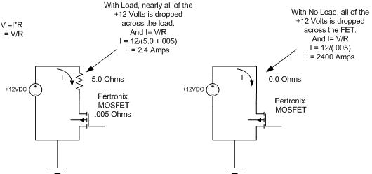
So if you try the test on the right, I am fairly sure you will blow up your Pertronix.
And based on the pictures above that is the configuration in the test.
Instead of a DC power supply, you could just use a DMM in resistance mode and that will not harm the FET
OK, I see the disconnect.
I've always used "no load" to mean an open circuit. In other words, there is no load attached. Light load means a high resistance and heavy load a low resistance.
Yeah, the circuit on the right would be very bad. I would call that one a shorted output.
Good discussion.
I've always used "no load" to mean an open circuit. In other words, there is no load attached. Light load means a high resistance and heavy load a low resistance.
Yeah, the circuit on the right would be very bad. I would call that one a shorted output.
Good discussion.
This is a "lo-fi" version of our main content. To view the full version with more information, formatting and images, please click here.